Valves clearance HONDA CR-V 1997 RD1-RD3 / 1.G Workshop Manual
[x] Cancel search | Manufacturer: HONDA, Model Year: 1997, Model line: CR-V, Model: HONDA CR-V 1997 RD1-RD3 / 1.GPages: 1395, PDF Size: 35.62 MB
Page 114 of 1395
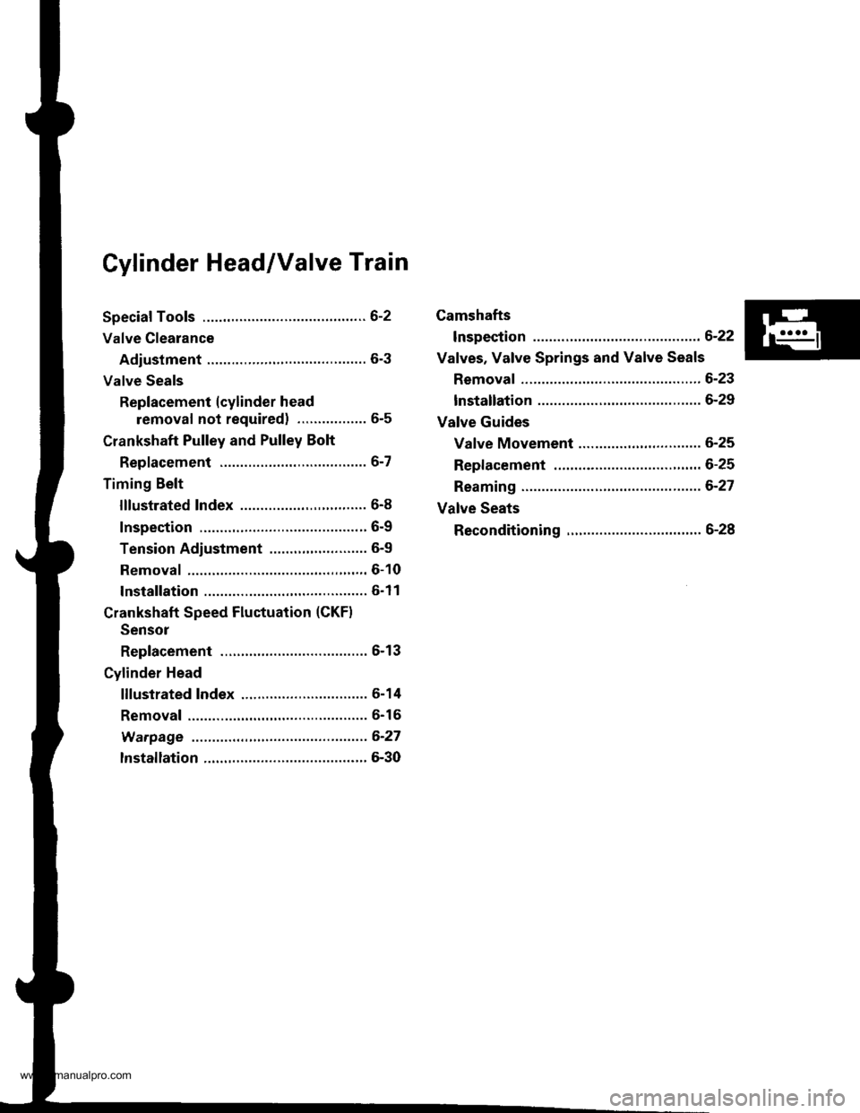
Cylinder Head/Valve Train
Speciaf Tools .............6-2
Valve Clearance
Adiustment ............6-3
Valve Seals
Replacement (cylinder head
removal not requiredl ................. 6-5
Crankshaft Pulley and Pulley Bolt
Replacement .........6-7
Timing Belt
I llustrated lndex ............................... 6-8
Inspection ............., 6-9
Tension Adjustment ........................ 6-9
Removal ...........,..... 6-10
lnstallation .............6-11
Crankshaft Speed Fluctuation (CKFI
Sensor
Replacement .........6-13
Cylinder Head
lllustrated lndex ............................... 6-14
Removal .................6-16
Warpage ................6-27
lnstallation ............. 6-30
Camshafts
lnspection ..............6-22
Valves, Valve Springs and Valve Seals
Removal ................, 6-23
lnstallation ............. 6-29
Valve Guides
Valve Movement ............,,,,.,............ 6-25
Replacement .........6-25
Reaming .................6-27
Valve Seats
Reconditioning ......6-28
www.emanualpro.com
Page 116 of 1395
Valve Clearance
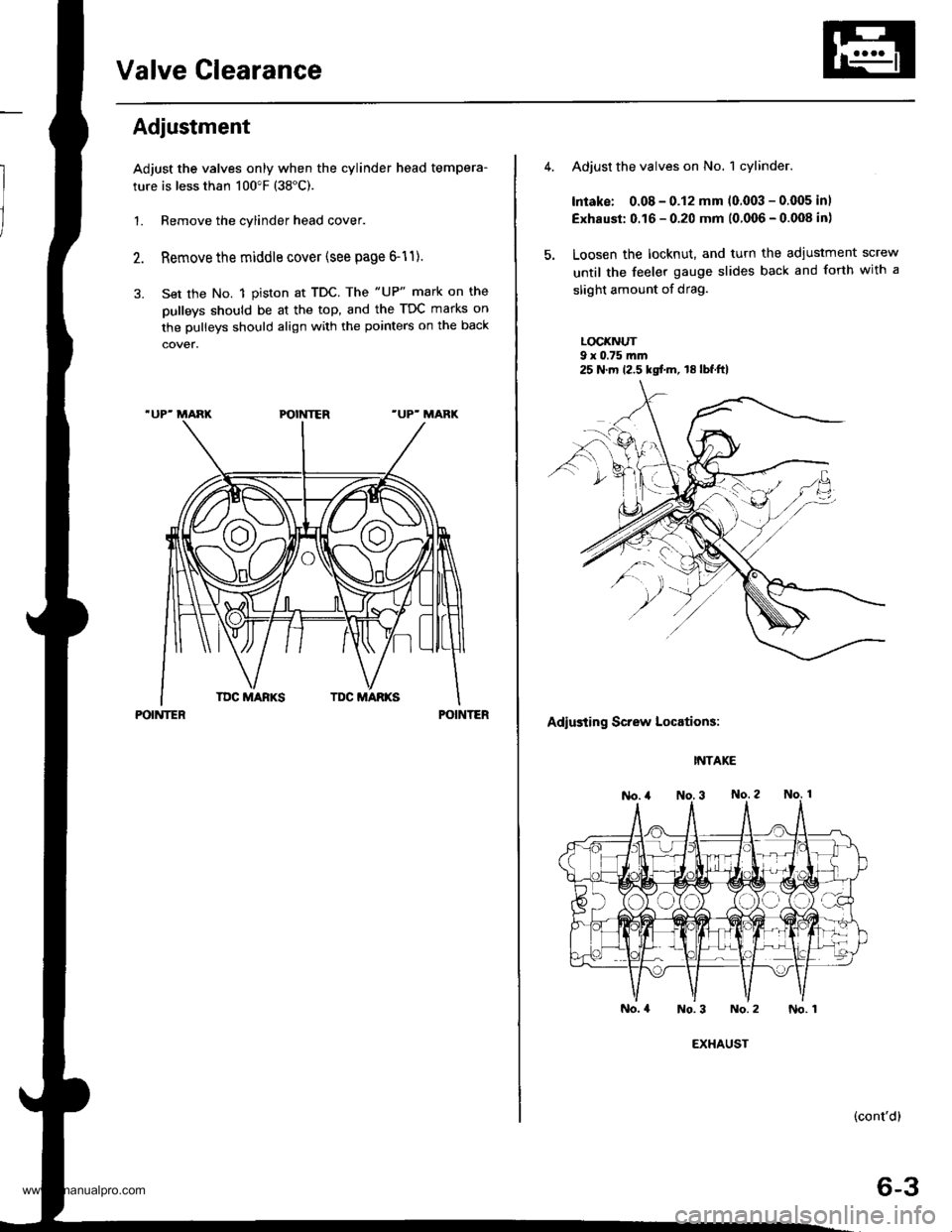
Adiustment
Adjust the valves only when the cylinder head tempera-
ture is less than 100"F (38"C).
1. Remove the cylinder head cover.
Remove the middle cover (see page 6-11).
Set the No. 1 piston at TDC. The "UP" mark on the
pulleys should be at the top, and the TDC marks on
the pulleys should align with the pointers on the back
POINTERPOINTER
Adjust the valves on No. 1 cylinder.
Intake: 0.08 - 0.12 mm (0.003 - 0.005 inl
Exhaust: 0.16 - 0.20 mm (0.006 - 0.008 in)
Loosen the locknut, and turn the adiustment screw
until the feeler gauge slides back and forth with a
slight amount of drag.
LOCI(NUT9 x 0.75 m.n
Adiusting Screw Locations:
INTAKE
No.4 No.3 No.2
(cont'd)
6-3
25 N.m 12.5 kgf.m, 18lbf.ft)
EXHAUST
No. 1
www.emanualpro.com
Page 117 of 1395
Valve Clearancev
Adjustment (cont'dl
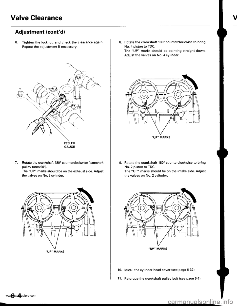
6. Tighten the locknut, and check the clearance agajn.
Repeat the adjustment if necessary.
GAUGE
Rotate the crankshaft 180" counterclockwise (camshaft
pulley turns 90').
The "UP" marks should be on the exhaust side. Adjust
the valves on No. 3 cylinder.
.UP" MARKS
7.
8. Rotate the crankshaft 180" counterclockwise to brinq
No. 4 piston to TDC.
The "UP" marks should be pointing straight down.
Adjust the valves on No. 4 cylinder.
Rotate the crankshaft 180'counterclockwise to brino
No.2 piston to TDC.
The "UP" marks should be on the intake side. Adiust
the valves on No. 2 cylinder.
Install the cylinder head cover (see page 6-32).
Retorque the crankshaft pulley bolt (see page 6-7).
10.
11.
"UP" MARKS
"UP" MARKS
www.emanualpro.com
Page 140 of 1395
Cylinder Head
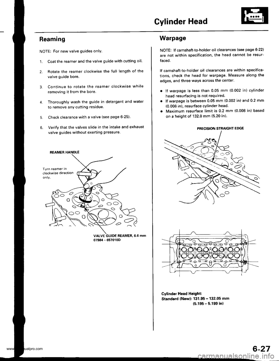
Reaming
NOTE: For new valve guides only.
1. Coat the reamer and the valve guide with cutting oil.
2. Rotate the reamer clockwise the full length of the
valve guide bore.
Continue to rotate the reamer clockwise while
removing it from the bore.
Thoroughly wash the guide in detergent and water
to remove anY cutting residue.
Check clearance with a valve (see page 6-25).
Verify that the valves slide in the intake and exhaust
valve guides without exerting pressure.
3.
4.
5.
6.
vALvE GUIDE REAMER,6.6 mm0798i1 - 657010O
REAMER HANDLE
e
Warpage
NOTE: lf camshaft-to-holder oil clearances (see page G22)
are not within specification, the head cannot be resur-
faced.
lf camshaft-to-holder oil clearances are within specifica-
tions, check the head for warpage. Measure along the
edges, and three ways across the center.
. if warpage is less than 0.05 mm (0.002 in) cylinder
head resurfacing is not required
lf warpage is between 0.05 mm (0.002 in) and 0.2 mm
(0.008 in), resurface cylinder head.
Maximum resurface limit is 0.2 mm (0.008 in) based
on a height of 132.0 mm (5.20 in).
Cylind€r Hesd Height:
Standard {New}: 131.95 - 132.05 mm
15.195 - 5.199 inl
PRECISION STRAIGHT EDGE
6-27
www.emanualpro.com
Page 328 of 1395
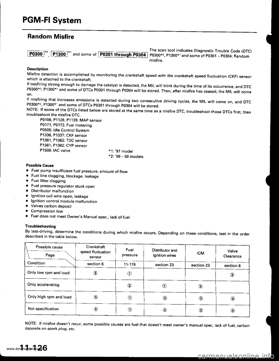
PGM-FI System
Random Misfire
lF()gool", tftod-' and some or lpiogol throughTo3oti
The scan tool indicates Diagnostic Trouble Code (DTC)
P0300*,, P1300*1 and some of po30t - pO3O4; Randommisfire.
Descriotion
Misfire detection is accomplished by monitoring the crankshaft speed with the crankshaft speed fluctuation (cKF) sensorwhich is attached to the crankshaft.lfmisfiring strong enough to damage the catalyst is detected, the MIL will blink during the time of its occurrence, and DTcP0300*'�, P1300*1 and some of DTCs P03ol through P0304 will be stored. Then, after misfire has ceased, the MtL will comeon,
lf misfiring that increases emissions is detected during two consecutive driving cycles, the MIL will come on, and DTcand some of DTCS p0301 through p0304 wi
be stored.NOTE: lf some of the DTCS listed below are stored at the same time as a misfire DTc, troubleshoot those DTcs first. thentroubleshoot the misfire DTC.
P0106, P]128, P1'129; MAp sensorP0171. P0172; Fuet metering
P0505: ldle Control Svstem
P1336, P1337; CKF sensor
P1361, P1362: TDC sensor
Pl381. Pl382: CYP sensor
P1508: IAC valve *1:,97 model*2: '98 - 00 models
Possiblo Caus€
. Fuel pump insufficient fuel pressure, amountofflow. Fuel line clogging. blockage, leakage. Fuel filter clogginga Fuel pressure regulator stuck open. Distributormalfunction
. lgnition coil wire open, leakage. lgnition control module malfunction. Valves carbon deposita Compression lowa Fuel does not meet Owner's Manual spec., lack offuel
Troubleshooting
By test-driving, determine the conditions during which misfire occurs. Depending on these conditions, test in the orderdescribed in the table below.
Possible cause
[ ;;;;- -....
Crankshaft
speed fluctuation
sensor
Fuel
pressureDistributor and
lgnition wirestcMValve
Clearance
Conditionsection 611-178section 23section 23section 6
Only low rpm and load,6)o
Only acceleratingooo
Only high rpm and loado@,a'@
Not specificationG\o@o@
NOTE: lf misfire doesn't recur, some possible causes are fuel that doesn't meet owner's manual spec, lack of fuel, carbondeposits on spark plu9, etc.
11-126
www.emanualpro.com
Page 670 of 1395
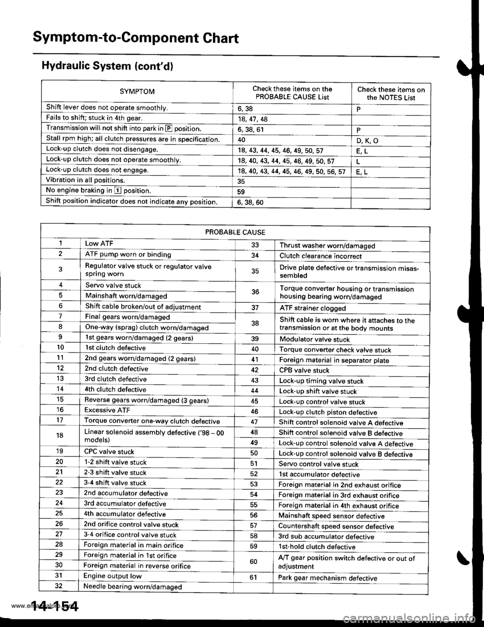
Symptom-to-Component Chart
Hydraulic System (cont'd)
SYMPTOMCheck these items on thePROBABLE CAUSE ListCheck these items onthe NOTES Lisr
Shift lever does not operate smoothly.o, JdPFails to shift; stuck in 4th gear.14, 41 , 48
Transmission will not shift into park in E position.6, 38, 61PStall rpm high; all clutch pressures are in specification.40D,K,OLock-up clutch does not disengage.18, 43, 44, 45, 46, 49,50,57
Lock-up clutch does not operate smoothly.14, 40, 43, 44, 45, 46, 49, 50. 57Lock-up clutch does not engage.'t8, 40, 43, 44, 45, 46, 49, 50, 56, 57Vibration in all positions.
No engine braking in I position.59
Shift position indicator does not indicate anv position,6. 38, 60
PROBABLE CAUSE
I 33 Thrust washer worn/damaged
ATF pump worn or binding34Clutch clearance incorrect
Regulator valve stuck or regulator valvespflng wornDrive plate delective or transmission mtsas-sembled
Servo valve stuck5ttTorque converter housing or transmissionhousing bearing worn/damagedMainshaft worn/damaged
Shift cable broken/out of adjustmentATF strainer clogged
7Final gears worn/damaged38Shift cable is worn where it attaches to thetransmission or at the body mountsIOne-way (sprag) clutch worn/damaged
1st gears worn/damaged {2 gears)39Modulator valve stuck10lst clutch defective40Torque converter check valve stuck112nd gears worn/damaged (2 gears)41Foreign material in separator plate't22nd clutch defectiveCPB valve stuck
t53rd clutch defective43Lock-up timing valve stuck144th clutch defective44Lock-up shift valve stucktcReverse gears worn/damaged (3 gears)Lock-up control valve stuck16Excessive ATF46Lock-up clutch Diston defective17Torque converter one-way clutch defective47Shift control solenoid valve A defecttve
18Linear solenoid assemblv defective (,98 - OOmodels)48Shift control solenoid valve B dsfectrve
49Lock-up control solenoid valve A defective'19CPC valve stuckLock-up control solenoid valve B deleqtve20l-2 shift valve stuck51Servo control valve stuck212-3 shift valve stuck52lst accumulator defective3-4 shift valve stuck53Foreign material in 2nd exhaust orifice2nd accumulator defective54Foreign material in 3rd exhaust orifice3rd accumulator defectiveForeign material in 4th exhaust orifice4th accumulator defective56Mainshaft speed sensor defective262nd orifice control valve stuckCountershaft speed sensor defective273-4 orifice control valve stuck583rd sub accumulator defective2aForeign material in main orifice59lst-hold clutch defective29Foreign material in lst orifice60A/T gear position switch defective or out ofadjustment30Foreign material in reverse orifice
31Engine output low61Park gear mechanism defective32Needle bearing worn/damaged
14-154
www.emanualpro.com
Page 671 of 1395
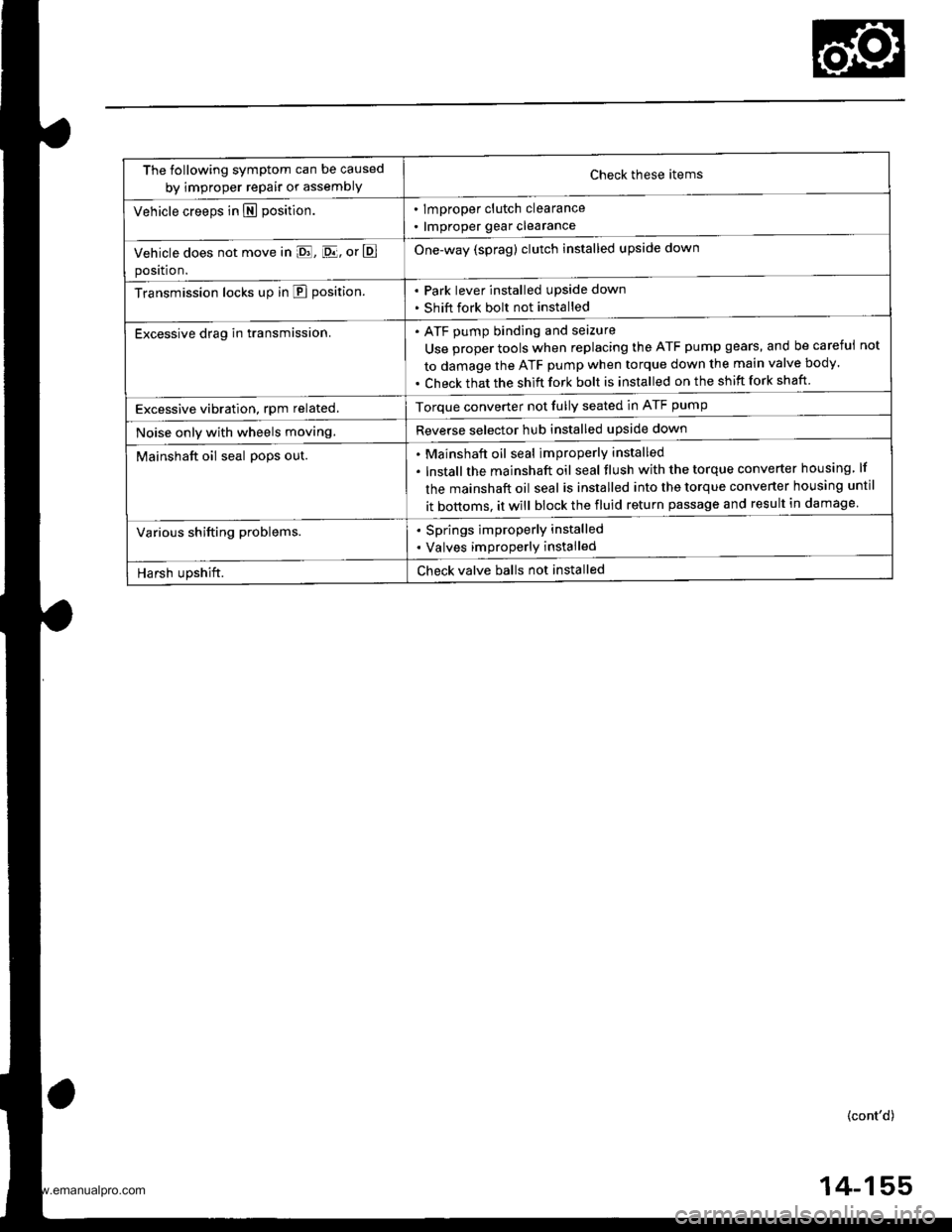
The following symptom can be caused
by improper repair or assemblYCheck these items
. lmproper clutch clearance
. lmproper gear clearance
One-way (sprag) clutch installed upside down
Park lever installed upside down
Shift fork bolt not installed
Vehicle creeps in N position.
Vehicle does not move in E, [D.lj, or E
position.
Transmission locks up in E position.
Excessive drag in transmission.ATF pump binding and seizure
Use proper tools when replacing the ATF pump gears, and be careful
to damage the ATF pump when torque down the main valve body.
Check that the shift fork bolt is installed on the shift fork shaft
not
Excessive vibration, rpm related.Torque converter not fully seated in ATF pump
Reverse selector hub installed upside downNoise only with wheels moving.
Mainshaft oil seal po9s out.Mainshaft oil seal improperly installed
lnstallthe mainshaft oil seal tlush with the torque converter housing lf
the mainshaft oil seal is installed into the torque converter housing until
it bottoms. it will block the fluid return passage and result in damage
Various shifting problems.. Springs improperly installed
. Valves improperly installed
Harsh upshift.Check valve balls not installed
(cont'd)
4-155
www.emanualpro.com