bolt pattern HONDA CR-V 1997 RD1-RD3 / 1.G Workshop Manual
[x] Cancel search | Manufacturer: HONDA, Model Year: 1997, Model line: CR-V, Model: HONDA CR-V 1997 RD1-RD3 / 1.GPages: 1395, PDF Size: 35.62 MB
Page 135 of 1395
Camshafts
4.
Inspection
1.
7.
Loosen the adjusting screws.
Remove the camshaft holders.
Mark the rocker arms, then remove them.
Reinstall the camshaft and holders. Tighten the
camshaft holder bolts in a crisscross pattern, begin-
ning with the inner bolts.
9.8 N.m (1.0 kgf.m.7.2 lbf.ft)
Seat the camshafts by pushing them toward the dis-
tributor end of the head with a screwdriver.
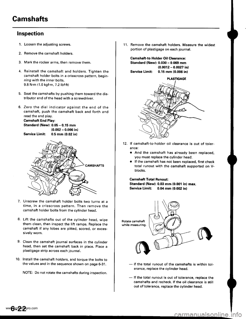
Zero the dial indicator against the end of the
camshaft, push the camshaft back and forth and
read the end play.
Camshaft End Play:
Standard lNewl: 0.05 - 0.15 mm
10.002 - 0.005 in)
Service Limit: 0.5 mm (0.02 in)
Unscrew the camshaft holder bolts two turns at a
time, in a crisscross pattern, Then remove the
camshaft holder bolts from the cvlinder head.
Lift the camshafts out of the cylinder head. wipe
them clean, then inspect the lift ramps, Replace the
camshaft if any lobes are pitted, scored, or exces-
sively worn.
Clean the camshaft journal surfaces in the cylinder
head, then set the camshaft back in Dlace. Place aplastigage strip across each journal.
Install the camshaft holders. and torque the bolts tothe values and in the sequence shown on page 6-31.
NOTE: Do not rotate the camshafts during inspection.
8.
10.
6-22
11. Remove the camshaft holders. Measure the widest
portion of plastigage on each journal.
Camshatt-to HoldGr Oil Clearance:
Standard {Newl: 0.030 - 0.069 mm
{0.0012 - 0.0027 in}
Servico Limit: 0.15 mm (0.006 in)
12. lf camshaft-to-holder oil clearance is out of toler-
ance:
. And the camshaft has already been replaced,
you must replace the cylinder head.. lf the camshaft has not been replaced, first check
total runout with the camshaft suoDorted on V-
blocks.
Camshaft Total Runout:
Standard (N6w): 0.03 mm (0.001 in) max.
Service Limit 0.04 mm (0.(X)2 in)
Rotat6 camshattwhile measuring.
- lf the total runout of the camshafts is within tol-
erance, replace the cylinder head
- lf the total runout is out of tolerance, replace the
camshafts and recheck. lf the oil clearance is still
out of tolerance, replace the cylinder head.
www.emanualpro.com
Page 434 of 1395
Pressure Plate
Removal/lnspection
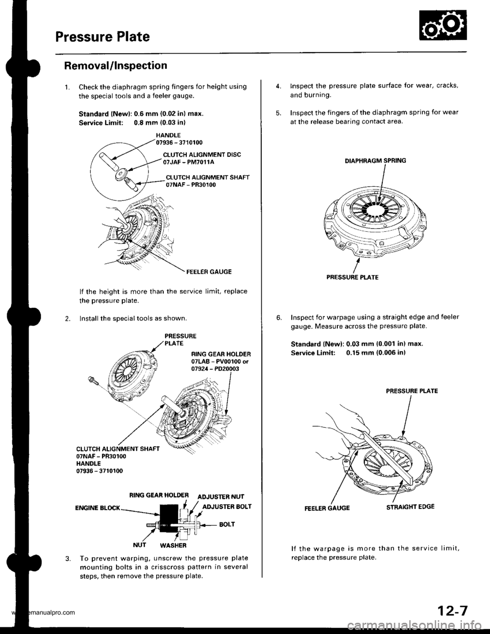
1.Check the diaphragm spring fingers for height using
the special tools and a feeler gauge.
Standard lNewl: 0.6 mm {0.02 in) max.
Service Limit: 0.8 mm (0.03 in)
HANDLE07936 - 3710100
CLUTCH ALIGNMENT DISCOTJAF - PM7O11A
CI.UTCH ALIGNMENT SHAFT07NAF - PR30100
FEELER GAUGE
lf the height is more than
the pressure Plate.
the service limit, replace
2. lnstall the sDeciallools as shown.
RING GEAR HOLDER ADJUSTER NUT
ENGINE BLOCKADJUSTER BOLT
BOLT
NUT WASHER
To prevent warping, unscrew the pressure plate
mounting bolts in a crisscross pattern in several
steps. then remove the pressure plate.
4. Inspect the pressure plate surface for wear, cracks,
and burning.
5. Inspect the fingers of the diaphragm spring for wear
at the release bearing contact area.
Inspect for warpage using a straight edge and feeler
gauge. Measure across the pressure plate.
Standard lNew): 0.03 mm 10.001 in) max.
Service Limit: 0.15 mm (0.006 inl
6.
FEELER GAUGE
lf the warpage is more than the service limit,
replace the pressure plate.
PRESSURE PLATE
PRESSURE PLATE
12-7
www.emanualpro.com
Page 436 of 1395
Flywheel
Inspection
2.
3.
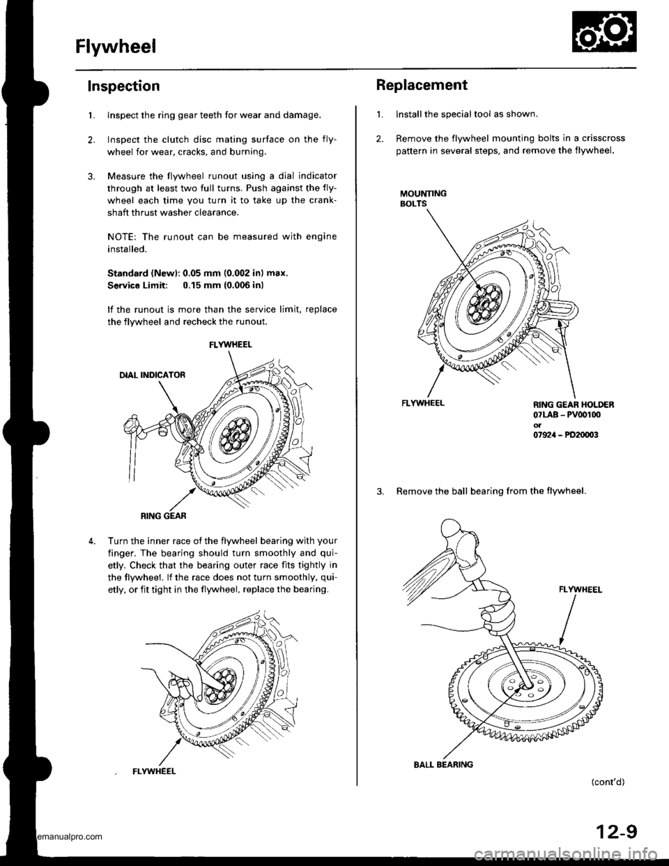
Llnspect the ring gear teeth for wear and damage.
Inspect the clutch disc mating surface on the fly-
wheel for wear, cracks, and burning
Measure the flywheel runout using a dial indicator
through at least two full turns. Push against the fly-
wheel each time you turn it to take up the crank-
shaft thrust washer clearance.
NOTE: The runout can be measured with engine
installed.
Standard (Newl: 0.05 mm (0.002 in) max.
Service Limit: 0.15 mm {0.006 inl
lf the runout is more than the service limit, replace
the flywheel and recheck the runout
Turn the inner race ot the flywheel bearing with your
finger. The bearing should turn smoothly and qui-
etly. Check that the bearing outer race fits tightly in
the tlywheel. lf the race does not turn smoothly, qui-
etly, or fit tight in the flywheel, replace the bearing.
FLYWHEEL
RING GEAR
FLYWHEEL
L
2.
Replacement
Installthe special tool as shown.
Remove the flywheel mounting bolts in a crisscross
pattern in several steps, and remove the flywheel.
MOUNNNGBOLTS
FLYWHEEL
(cont'd)
12-9
RING GEAR HOLDER07LAB - PV00r00ol07924 - PD20003
3. Remove the ball bearing from the flywheel.
BALL BEARING
www.emanualpro.com
Page 437 of 1395
FlywheelClutch Disc, Pressure Plate
Replacement (cont'dl
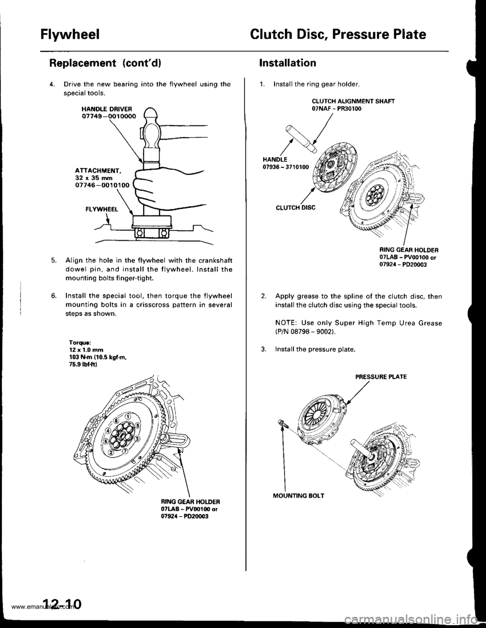
Drive the new bearing
specialtools.
HANOLE DRIVER07749-
ATTACHMET{T-32x35mm07746 -O010100
FLYWHECI-
Align the hole in the flywheel with the crankshaft
dowel pin, and install the flywheel. Install the
mounting bolts finger-tight.
Install the special tool, then torque the flywheel
mounting bolts in a crisscross pattern in several
steps as shown.
Torque:12 x 1.0 mmr03 N.m (10.5 kgl.ln,75.9 tbtftl
into the flywheel using the
12-10
Installation
1. Install the ring gear holder.
CLUTCH ALIGNMENT SHAFT07NAF - PR30100
CLUTCH DISC
RING GEAR HOLDER07LAB _ pvoot(x) or07924 _ PD20003
Apply grease to the spline of the clutch disc, then
install the clutch disc using the special tools.
NOTE: Use only Super High Temp Urea Grease(P/N 08798 - 9002).
lnstall the pressure plate.
PRESSURE PLATE
www.emanualpro.com
Page 438 of 1395
Release Bearing
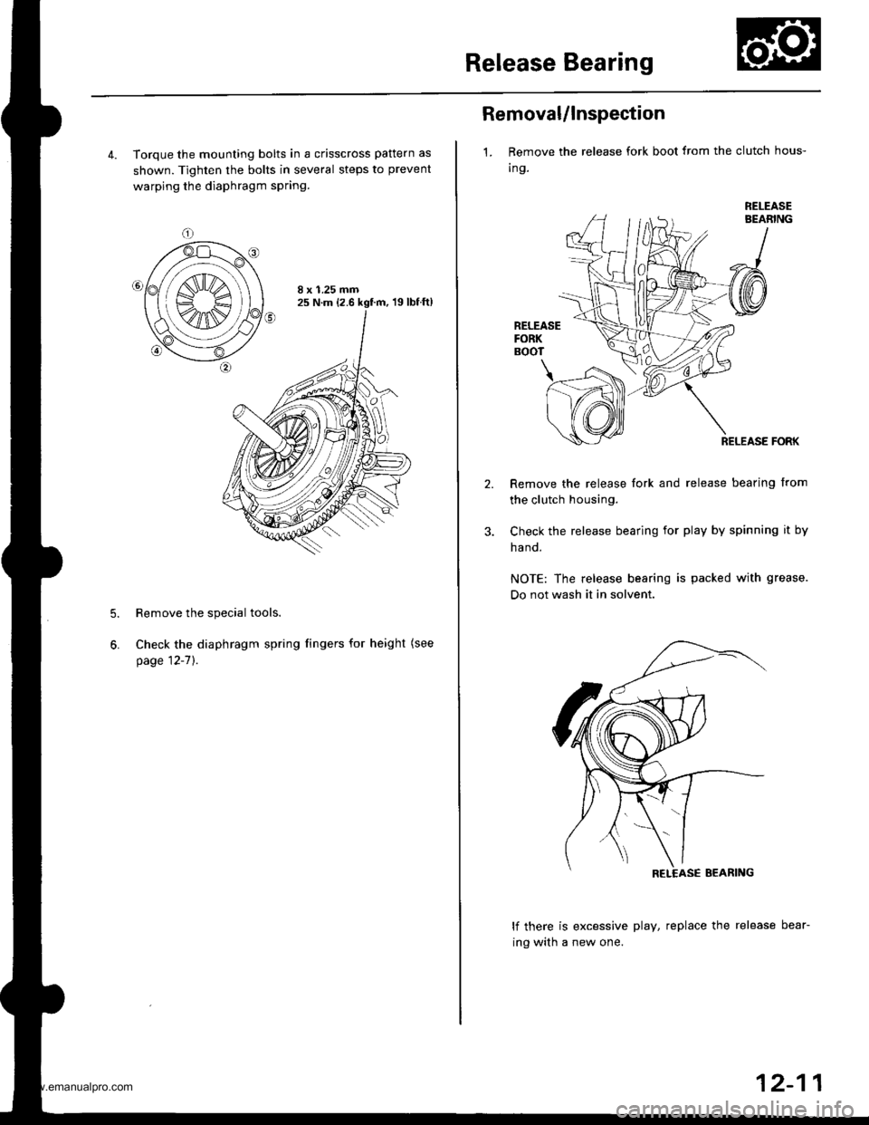
4. Torque the mounting bolts in a crisscross pattern as
shown. Tighten the bolts in several steps to prevent
warping the diaphragm spring.
8 x 1.25 mm25 N.m (2.6 kgf.m, 19lbfft)
Remove the special tools.
Check the diaphragm spring fingers for height (see
page 12-7]'.
5.
6.
Removal/lnspection
1. Remove the release fork boot from the clutch hous-
Ing.
RELEASEBEABING
RELEASEFORKBOOT
\
RELEASE FORK
Remove the release fork and release bearing from
the clutch housing.
Check the release bearing for play by spinning it by
ha nd.
NOTE: The release bearing is packed with grease.
Do not wash it in solvent.
lf there is excessive play, replace the release bear-
ing with a new one.
12-11
www.emanualpro.com
Page 478 of 1395
Final Driven Gear RePlacement
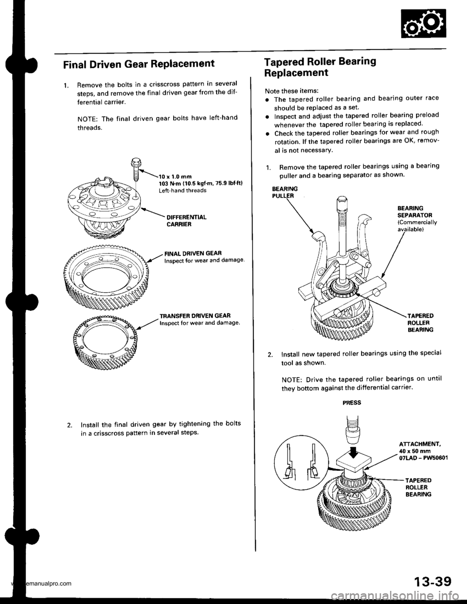
LRemove the bolts in a crisscross pattern in several
steps, and remove the final driven gear from the dif-
ferential carrier.
NOTE: The final driven gear bolts have left-hand
threads.
10 x 1.0 mm103 N.m (10.5 kgf m,75.9lbf'ftlLeft'hand threads
FINAL DRIVEN GEAR
lnsoect {or weal and damage
TRANSFER ORIVEN GEARInspect for wear and damage.
Install the final driven gear by tightening the bolts
in a crisscross pattern in several steps.
Tapered Roller Bearing
Replacement
Note these items:
. The tapered roller bearing and bearing outer race
should be replaced as a set.
. Inspect and adiust the tapered roller bearing preload
whenever the tapered roller bearing is replaced'
. Check the tapered roller bearings for wear and rough
rotation. lf the tapered roller bearings are OK, remov-
al is not necessary.
1. Remove the tapered roller bearings using a bearing
puller and a bearing separator as shown.
Install new tapered roller bearings using the special
tool as shown.
NOTE: Drive the tapered roller bearings on until
they bottom against the differential carrter.
PRESS
IJ
BEARINGSEPAFATOB{Commercially
ATTACHMENT,,10 x 50 mm07LAD - PWs060 l
BEARING
13-39
www.emanualpro.com
Page 509 of 1395
Transmission Assembly
Reassembly lcont'd)
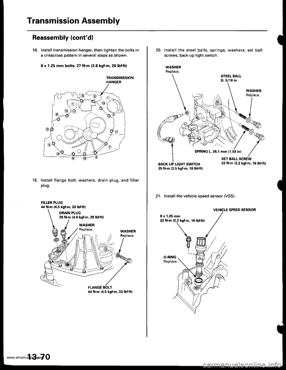
18. Installtransmission hanger, then tighten the bolts in
a crisscross pattern in several steps as shown.
8 x 1.25 mm bolis: 27 N.m 12.8 kgf.m,20 lbf'ft}
TRANSMISSIONHANGER
19.Install flange bolt,
plug.
washers, drain plug. and filler
FILLER PLUG4,r N.m (a.5 kgl.m,33lbtftl
DRAIN PLUG39 N.m {4.0 kg{.m,29lbtftl
WASHERReplace.WASHER
13-70
20. Install the steel balls, springs. washers, set ball
screws, back-up light switch.
WASHERReplace.
STEEL BALLD,5/16 in
21. Installthe vehicle speed sensor (VSS).
VEHICI."E SPEED SENSOR
8 x 1.25 mm22 N.m 12.2 kgl.m, 16 lbt.ftl
SPRING L.26.1 mm 11.03 inl
www.emanualpro.com
Page 776 of 1395
Transmission
Installation (cont'dl
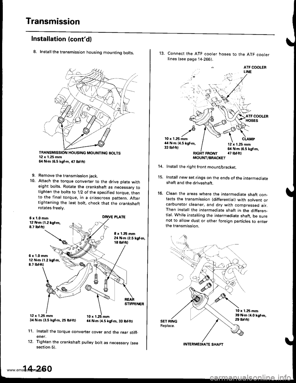
8. Install the transmission housing mounting bolts.
TRANSMISSION HOUSING MOUNTING BOLTS12 x 1.25 mm54 N.m 16,5 kgf.m, a7 lbtftl
9. Remove the transmission jack.
10. Attach the torque convener to the drive plate witheight bolts. Rotate the crankshaft as necessarv totighten the bolts to 'll2 of the specified torque, thento the final torque, in a crisscross pattern. Aftertightening the last bolt. check that the crankshaftrotates freelv.
6x1.0mln12 N.m (1.2 tgt m,8.t lbf.frl
6x1.0mm12 N.m {1.219{.m,8.7 tbtft,
12 x t.25 mm34 N.m 13.5 kgf.rn,25 lbf.ft)
8 x 1.25 mm2a N.m 12.5 kgf'm,18 tbt.ftl
DRIVE PLATE
STIFFENER
44 N.rn (4.5 kgt m, 33 lbtftl
11.
12.
Install the torque convener cover and the rear stiff_ener.
Tighten the crankshaft pulley bolt as necessary (seesection 5).
14-260
13. Connect the ATF cooler hoses to the ATF coolerlines (see page 14-266).
. ATF COOLERLINE
'i 'l'r',:,.) -
10 x 1.25 mm44 N.m (4.5 kgf.m,33 tbtftl
CLAMP
12 x 1.25 mm64 N.m 16.5 kg{.m,a7 tbt.ftlFRotrtT
15.
16.
't 4.
SET RINGReplace.
MOUNT/ARACKET
Install the right front mounvbracket.
Install new set rings on the ends of the intermediateshaft and the driveshaft.
Clean the areas where the intermediate shaft con_tacts the transmission {differential) with solvent orcarburetor cleaner, and dry with compressed air.Then install the intermediate shaft in the differen_tial, While installing the intermediate shaft, be surenot to allow dust or other foreign panicles to enterthe transmission.
l0 x 1.25 mm39 N.m 14.0 kgt.n,29 tbf.ftl
INTERMEDIATE SHAFT
www.emanualpro.com
Page 808 of 1395
Differential Carrier Assembly
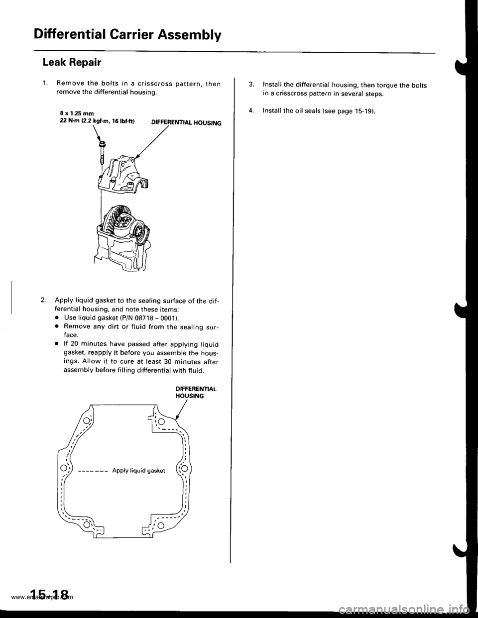
Leak Repair
'1. Remove the bolts in a crisscross oattern. thenremove the differential housing.
I x 1.25 mm22 N.m 12.2 kgl.m, 16 tbtftlDIFFERENTIAL HOUSING
2.Apply liquid gasket to the sealing surface of the dit-ferential housing, and note these items:. Use liquid gasket (P/N 08718 - 000'1).. Remove any dirt or fluid from the sealing sur-lace.
. lf 20 minutes have passed after applying liquidgasket, reapply it before you assemble the hous-
ings. Allow it to cure at least 30 minutes afterassembly before filling differential with ftuid.
DIFFERENTIALHOUSING
15-18
Install the differential housing. then torque the boltsin a crisscross pattern in several steps.
Install the oil seals (see page 15-19).
www.emanualpro.com