change time HONDA CR-V 1997 RD1-RD3 / 1.G Workshop Manual
[x] Cancel search | Manufacturer: HONDA, Model Year: 1997, Model line: CR-V, Model: HONDA CR-V 1997 RD1-RD3 / 1.GPages: 1395, PDF Size: 35.62 MB
Page 21 of 1395
Lift and Support Points
Lift and Safety Stands
ffi When heaw rear components such as suspension, Iuel tank, spare tire and tailgate are to b€ lemoved, place
!iiii-'rn"t r""igtrt in the trunk before hoisting. When substantial weight is removed flom the lear ot the vehicle, the
center of gravity may change and can cause the vehicle to tip fotward on the hoist'
NOTE: Since each tire/wheel assembly weighs approximately 30 lbs (14 kg), placing the front wheels in the cargo area can
assist with weight distribution.
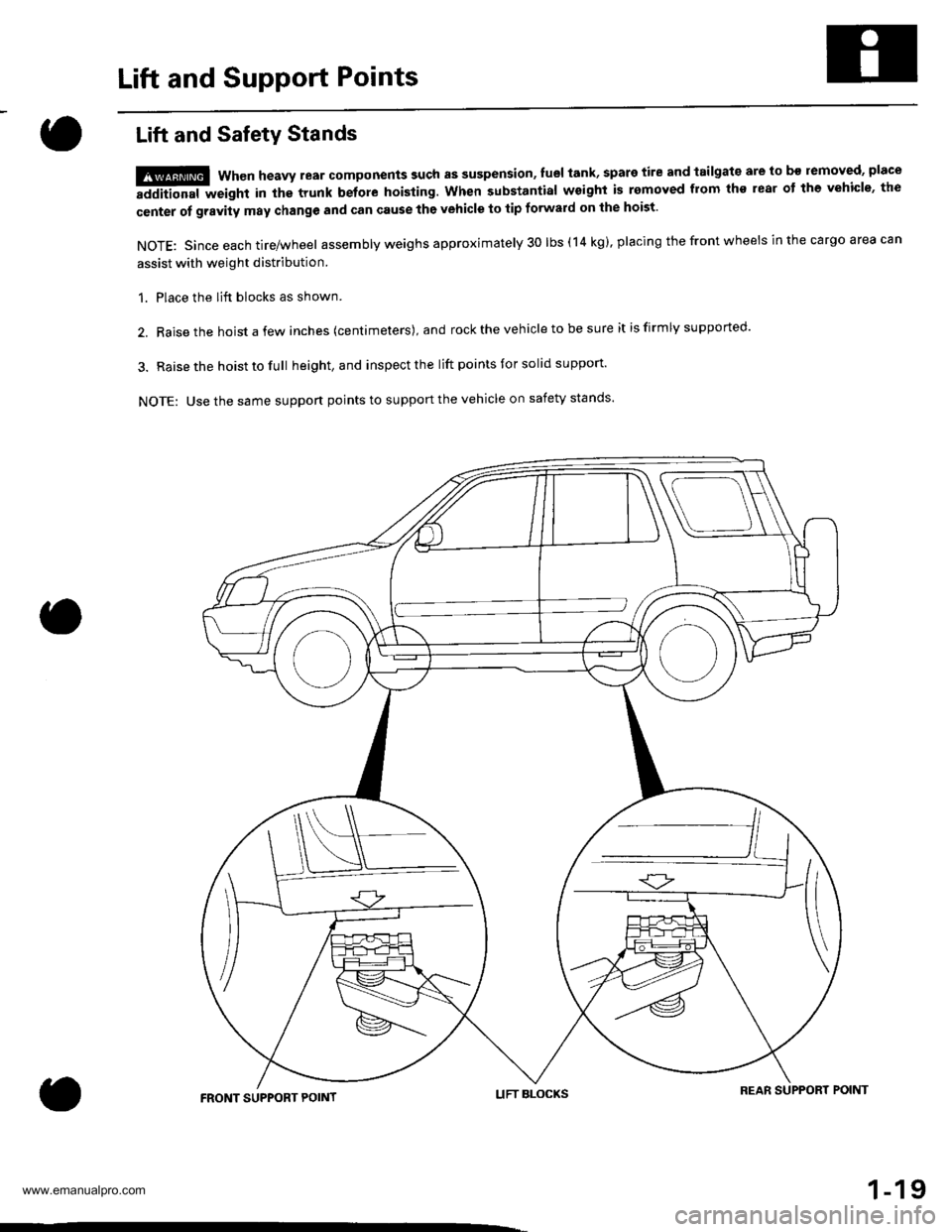
1. Place the lift blocks as shown.
2. Raise the hoist a few inches (centimeters), and rock the vehicle to be sure it is firmly supported.
3. Raise the hoist to full height, and inspect the lift points for solid support'
NOTE: Use the same suppon points to support the vehicle on safety stands'
LIFT BLOCKSREAR SUPPORT POIMTFRONT SUPPORT POINT
1-19
www.emanualpro.com
Page 142 of 1395
Valves, Valve Springs and Valve Seals
lnstallation
Coat the valve stems with oil. Insert the valves into
the valve guides.
Check that the valves move up and down smoothly.
Install the spring seats on the cylinder head.
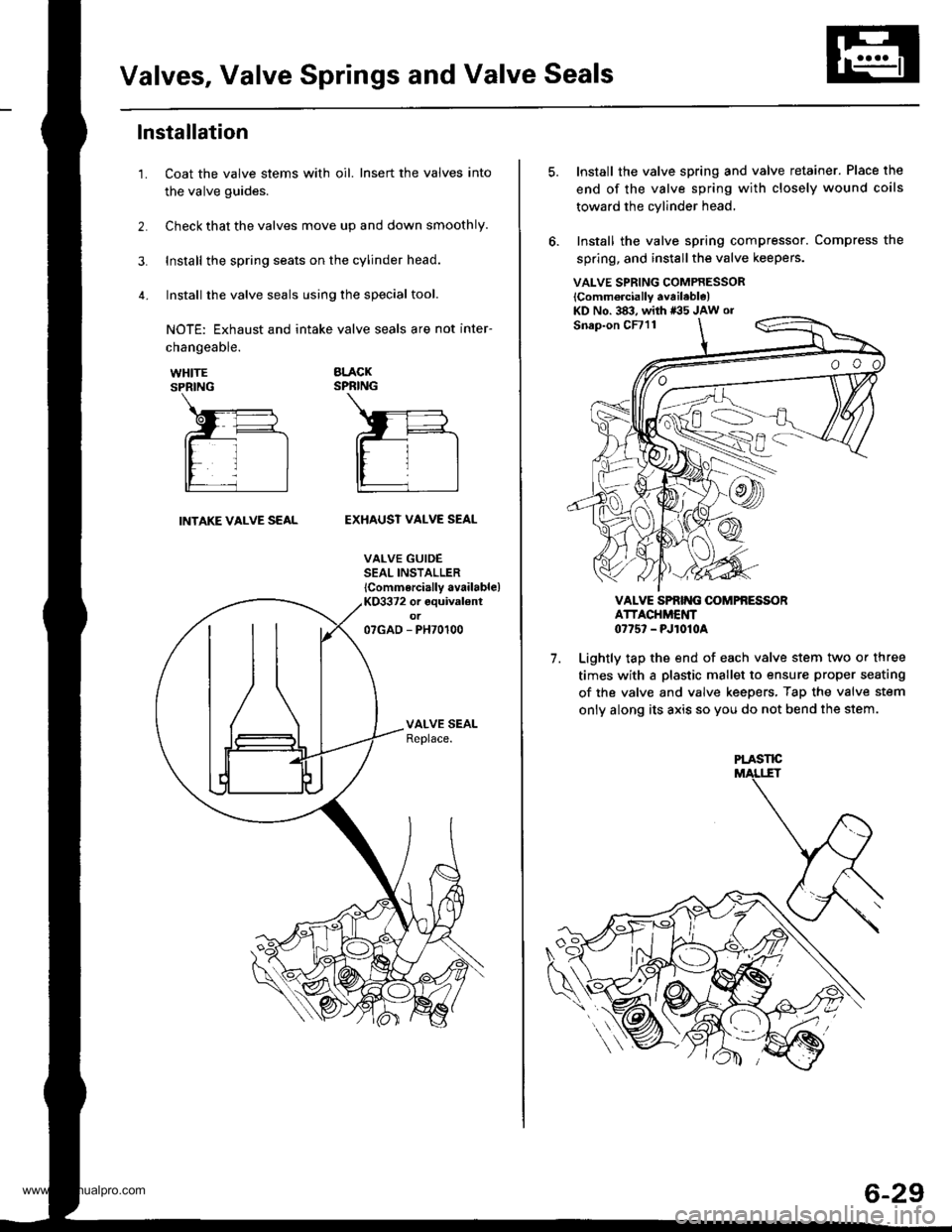
Install the valve seals using the special tool.
NOTE: Exhaust and intake valve seals are not inter-
1.
changeable.
WHITESPRING
BLACKSPRING
INTAKE VALVE SEALEXHAUST VALVE SEAL
VALVE GUIDESEAL INSTALLER
lCommercially available)KO3372 or equival€ntot07GAD - PH70100
VALVE SPRING COMPRESSOR
lComm6rcially available)KD No. 383, with *35 JAw or
7.
Install the valve spring and valve retainer. Place the
end of the valve spring with closely wound coils
toward the cylinder head,
Install the valve spring compressor. Compress the
spring, and install the valve keepers.
VALVE SPRIT{G OOMPfi ESSORATTACHMENT0775' - PJ1010A
Lightly tap the end of each valve stem two or three
times with a plastic mallet to ensure proper seating
of the valve and valve keepers, Tap the valve stem
only along its axis so you do not bend the stem.
PLASTE
6-29
www.emanualpro.com
Page 267 of 1395
ECM/PCM Data
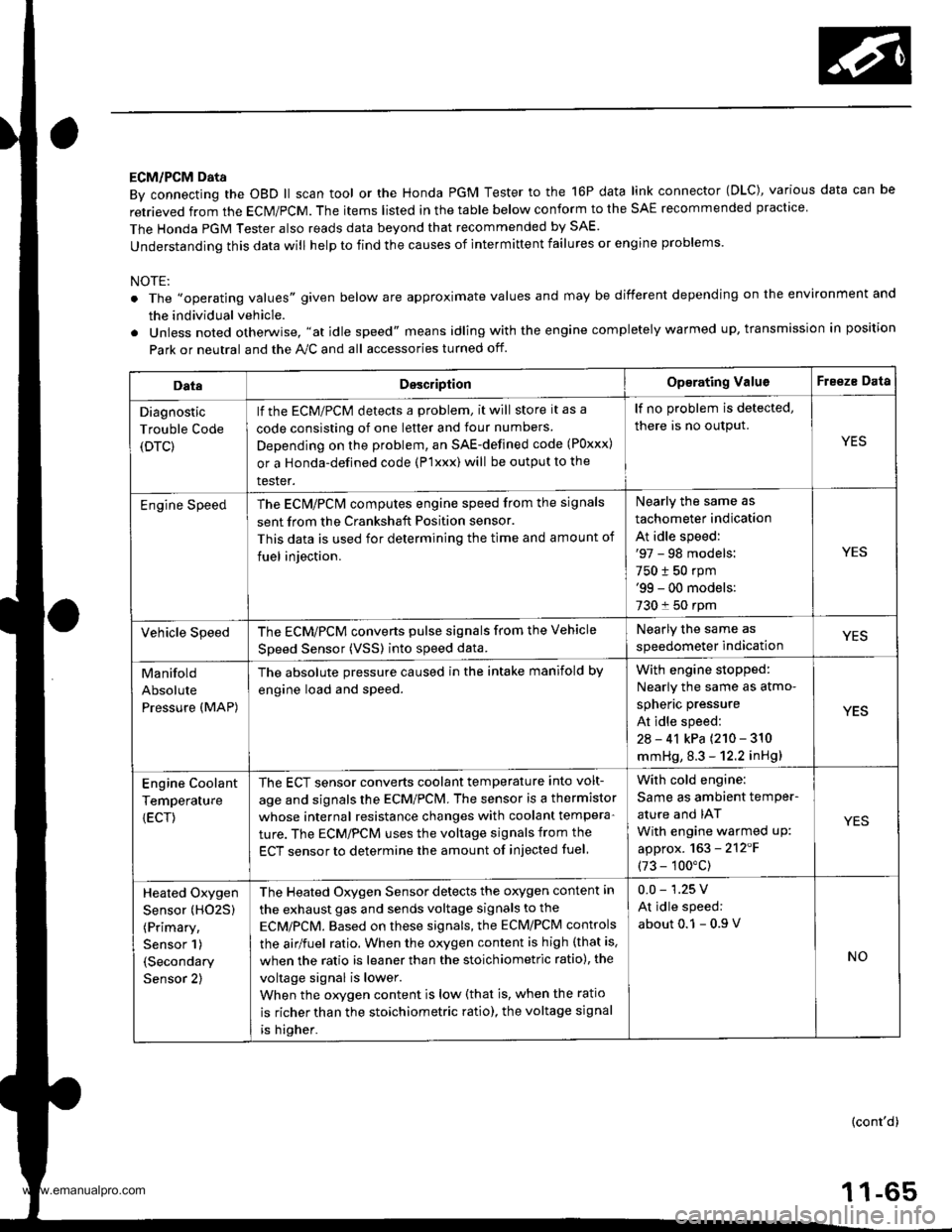
By connecting the OBD ll scan tool or the Honda PGM Tester to the 16P data link connector (OLC), various data can be
retrieved from the ECM/PCM. The items listed in the table below conform to the SAE recommended practice
The Honda PGM Tester also reads data beyond that recommended by SAE.
understanding this data will help to find the causes of intermittent failures or engine problems.
NOTE:
The ',operating values" given below are approximate values and may be different depending on the environment and
the individual vehicle.
Unless noted otherwise. "at idle speed" means idling with the engine completely warmed up, transmission in position
Park or neutral and the A,./C and all accessories turned otf.
DataDesc.iptionOp€rating ValuoFreeze Data
Diagnostic
Trouble Code
(DTC)
lf the ECM/PCM detects a problem, it will store it as a
code consisting of one letter and tour numbers
Depending on the problem, an SAE-defined code (Poxxx)
or a Honda-defined code (P'lxxx) will be output to the
tester.
lf no problem is detected,
there is no output.
YES
Engine SpeedThe ECN4/PCN4 computes engine speed from the signals
sent from the Crankshaft Position sensor.
This data is used for determining the time and amount of
fuel iniection.
Nearly the same as
tachometer indication
At idle speed:'97 - 98 models:
750 t 50 rpm'99 - 00 models:
730 f 50 rpm
YES
Vehicle SpeedThe ECM/PCM converts pulse signals from the Vehicle
Speed Sensor (VSSI into speed data.
Nearly the same as
speedometer indicationYES
Manifold
Absolute
Pressure (MAP)
The absolute pressure caused in the intake manifold by
engine load and speed.
With engin6 stopped:
Nearly the same as atmo-
spheric pressure
At idle speed:
2a - 41 kPa {210 - 310
mmHg, 8.3 - 12.2 inHg)
YES
Engine Coolant
Temperature
{ECT)
The ECT sensor converts coolant temperature into volt-
age and signals the ECM/PCM. The sensor is a thermistor
whose internal resistance changes with coolant tempera-
ture. The ECM/PCM uses the voltage signals from the
ECT sensor to determine the amount of injected fuel
With cold engine:
Same as ambient temPer-
ature and IAT
With engine warmed uP:
approx. 163 - 2'12'F
(73 - 100"c)
YES
Heated Oxygen
Sensor (HO25)
(Primary,
Sensor 1)
(Secondary
Sensor 2)
The Heated Oxygen Sensor detects the oxygen content in
the exhaust gas and sends voltage signals to the
ECMiPCM. Based on these signals, the ECM/PCM controls
the airlfuel ratio. When the oxygen content is high (that is.
when the ratio is leaner than the stoichiometric ratio), the
voltage signal is lower.
When the orygen content is low (that is, when the ratio
is richer than the stoichiometric ratio), the voltage signal
is higher.
0.0 - 1.25 V
At idle speed:
about 0.1 - 0.9
NO
(cont'd)
1 1-65
www.emanualpro.com
Page 330 of 1395
PGM-FI System
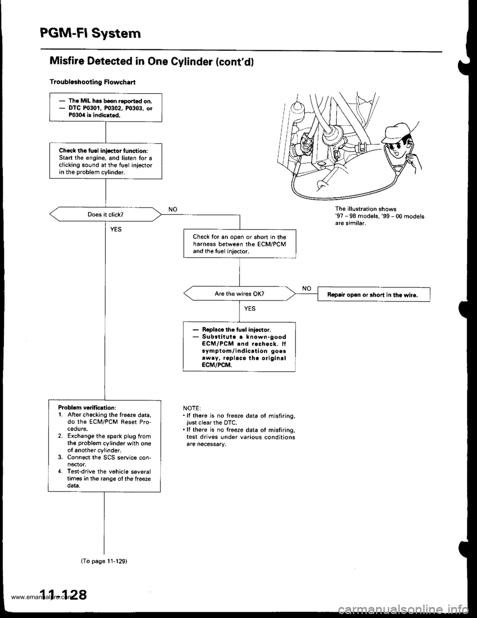
Misfire Detested in One Cylinder (cont'dl
Troubl93hooting Flowchart
The illu stration shows'97 - 98 models,'99 - 00 modelsare similar.
NOTE:.lf there is no freeze data ol misfiring,just clear the DTC..lf there is no freeze data ot misfiring,test drives under various conditionsare necessary,
- Th. MIL h!3 b6on r.portod on.- DTC m30r, P0302, m303. orP0304 is indicated.
Ch.ck tho fuol inicctor tunction:Start the engino, and listen for Iclicking sound at the fuol injectorin the probl€m cylinder.
Check for an open or short in theharness between the ECM/PCMand the luel injector.
Boprir opan or 3hort in tha wlre.
- Roplaco th. tuel inioctor.- Substitut. . known-goodECM/PCM .nd rochock. It3ym ptom/ indicati on go.3aw.y, replace the oliginalECM/PCM.
Problom vorification:1. Atter chacking the lre€ze data,do the ECM/PCM Reset Pro-cedure.2. Exchange the spark plug fromthe problem cylinder with oneol another cylinder.3. Connect the SCS service con-nector.4. Tost-drive the vohicle severaltimes in the rango ol the freezedata.
(To page'11-129)
11-128
www.emanualpro.com
Page 331 of 1395
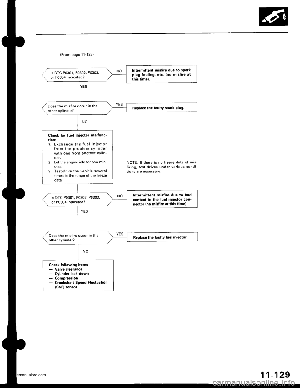
(From page 11-128)
lntormittent misfire due lo sparkplug fouling, etc. (no mislire at
this tim€).
ls DTC P0301, P0302, P0303,or P0304 indicated?
ooes the misfire occur in theother cylinder?Replace the faulty spark Plug.
Check lor fuel iniector maltunc-
t|on:1. Exchange the fuel injectorfrom the problem cylinderwith one from another cylin-der.2. Let the engine idle for two min
utes.3. Test'drive the vehicle severaltimes in the range of the freezedata,
lntermittent misfiro due lo bad
contrct in the fuel iniector con-nector {no misfire at this time).
ls DTC P0301, P0302, P0303,or P0304 indicated?
Does the misfire occur in theother cylinder?Replace lhe faulty luel inlector.
Check following items- Valvo clearance- Cvlinder l€ak-down- Compression- Crsnkshaft Speed FluctuationICKF) sensol
NOTE: lf there is no freeze data of misfiring, test drives under various condi_
tions are necessary.
11-129
www.emanualpro.com
Page 351 of 1395
ldle Control System
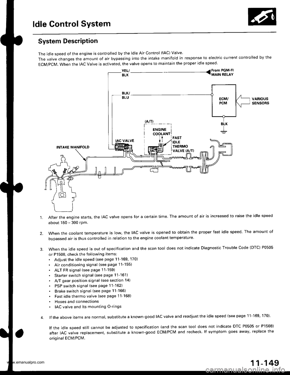
System Description
The idle speed of the engjne is controlled by the ldle Air Control (lAC) Valve'
The valve changes the amount of air bypassing into the intake manifold in response to electric current controlled by the
ECM/PCM. When the lAc valve is activated, the valve opens to maintain the proper idle speed.
YEL/ From PGM'FI
BLK TMAIN RELAY
VARIOUSSENSORS
4.
IAC VALVE
INTAKE MANIFOLD
After the engine starts, the IAC valve opens for a certain time. The amount of air is increased to raise the idle speed
about 150 - 300 rpm.
when the cootant temperature ts row, the lAc valve is opened to obtain the proper fast idle speed The amount o{
bvoassed air is thus controlled in relation to the engine coolant temperature
When the idle speed is out o{ specification and the scan tool does not indicate Diagnostic Trouble Code (DTC) P0505
or P1508, check the following items:
. Adjust the idle speed (see page 11-169, 170)
. Air conditioning signal (seepagell-1551
. ALT FR signal (see page 1l-159)
. Starter switch signal (see page 11-16'1)
. A,/T gear position signal (see section 14)
. PSP switch signal (seepagell-162)
. Brake switch signal (see page 11-165)
. Fast idlethermovalve (see page'11 168)
. Hoses and connecttons. IAC valve and its mounting O-rings
lf the above items are normat, suDslitute a known-good IAC valve and readjust the idle speed {see page 11-169, 170)
lf the idle speed still cannot be adjusted to specification (and the scan tool does not indicate DTC P0505 or Pl508)
after IAC valve reolacement, substitute a known-good ECM/PCM and recheck lf symptom goes away' replace the
original ECM/PCM.
11-149
www.emanualpro.com
Page 354 of 1395
ldle Control System
ldle Air Control llAC) Valve
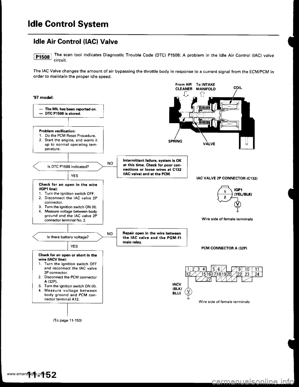
The scan tool indicates Diagnostic Trouble Code (DTC) Pl508: A probtem in the ldle Air Controt flAC) varvecircuit.
The IAC Valve changes the amount of air bypassing the throttle body in response to a current signal from the ECM/PCM inorder to maintain the proper idle speed.
37 model;
IAC VALVE 2P CONNECTOR {C132}
,f rcp'# IYEL/BI.(II2f-1-d)
Y
Wir€ side of female terminals
PCM CONNECTOR A I32PI
tacvIBLK/BLU)
From AIR To INTAKECLEANER MANIFOLD
Wire side of female terminals
The MIL has beon .eport€d on.OIC Pl508 is sto.ed.
Problem veiification:1. Do the PCM Reset Procedure.2. Start the engine, and warm itup to normal operating tem-perature.
Inte.mittent failure, systcm b OKat thi3 time. Check tor poo. con-nections or loose wircs at C132(lAC v.lvel and at the PCM.
ls DTC Pl508 indicated?
Check lor an open in the wir6{lGPl lins}:1. Turn the ignition switch OFF.2. Disconnect the IAC valve 2Pconnector.3. Turn the ignition switch ON {ll).4. Measure voltage between bodyground and the IAC valve 2Pconnector term inal No.2.
Repair open in the wire trctwoontha IAC v!lv6 and the PGM-Flmain relly.
Chock for an opan o. short in thowi.e (lACv linel:1. Turn the ignition switch OFFand reconnect the IAC valve2P connector.2. Disconnect the PCM conneclorA (32P).
3. Turn the ignition switch ON {ll).4, Measure voltage betweenbody ground and PCM con-nector terminal A12.
{To page 1l-153)
www.emanualpro.com
Page 939 of 1395
6.
7.
8.
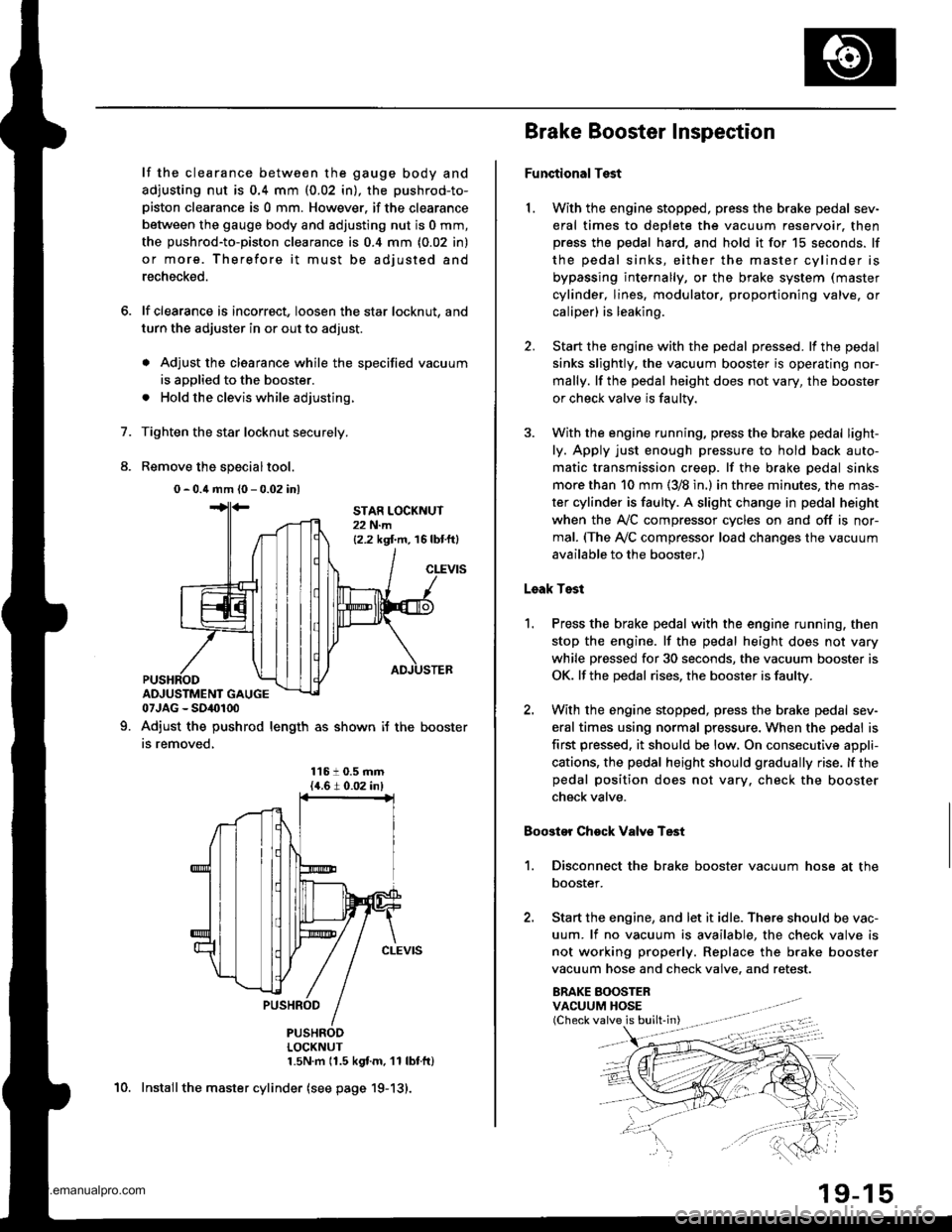
lf the clearance between the gauge body and
adjusting nut is 0.4 mm (0.02 in), the pushrod-to-
piston clearance is 0 mm. However. if the clearance
between the gauge body and adjusting nut is 0 mm,
the pushrod-to-piston clearance is 0.4 mm (0.02 in)
or more. Therefore it must be adjusted and
recheck€d.
lf clearance is incorrect, loosen the star locknut, and
turn the adjuster in or out to adjust.
. Adjust the clearance while the specified vacuum
is applied to the booster.
. Hold the clevis while adjusting.
Tighten the star locknut securely.
Remove the special tool.
0 - 0.4 mm (0 - 0.02 inl
Adjust the pushrod length as shown if the
is removed,
booster
11610.5 mm{4.6 t 0.02 inl
PUSHRODLOCKNUT1.5N.m 11.5 kgf.m. '11 lbtfl)
Install the master cylinder (see page 19-13).
9.
STAR LOCKNUT22 N.m12.2 kgt m. 16 lbtftl
10.
(Check valve is built-in)
Brake Booster Inspection
FunctionalTest
1. With the engine stopped, press the brake pedal sev-
eral times to deplete the vacuum reservoir. thenpress the pedal hard, and hold it for 15 seconds. lf
the pedal sinks, either the master cylinder is
bypassing internally, or the brake system (master
cylinder, lines, modulator, proportioning valve. or
caliper) is leaking.
2. Start the engine with the pedal pressed. lf the pedal
sinks slightly. the vacuum booster is operating nor-
mally. lf the pedal height does not vary, the booster
or check valve is faultv.
3. With the engine running, press the brake pedal light-
ly. Apply just enough pressure to hold back auto-
matic transmission creep. lf the brake pedal sinks
more than 10 mm (3/8 in.) in three minutes, the mas-
ter cylinder is faulty. A slight change in pedal height
when the Ay'C compressor cycles on and off is nor-
mal. (The Ay'C compressor load changes the vacuum
available to the booster.)
Leak Test
1.Press the brake pedal with the engine running, then
stop the engine. lf the pedal height does not vary
while pressed for 30 seconds, the vacuum booster is
OK. lf the pedal rises, the booster is faulty.
With the engine stopped, press the brake pedal sev-
eral times using normal pressure. When the pedal is
first pressed. it should be low, On consecutive appli-
cations, the pedal height should gradually rise. lf thepedal position does not vary. check the booster
check valve.
Boostor Chock Valve Test
1. Disconnect the brake booster vacuum hose at the
booster.
2. Start the engine, and let it idle. There should be vac-
uum. lf no vacuum is available, the check valve is
not working properly. Replace the brake booster
vacuum hose and check valve. and retest.
ERAKE BOOSTERVACUUM HOSE
www.emanualpro.com
Page 954 of 1395
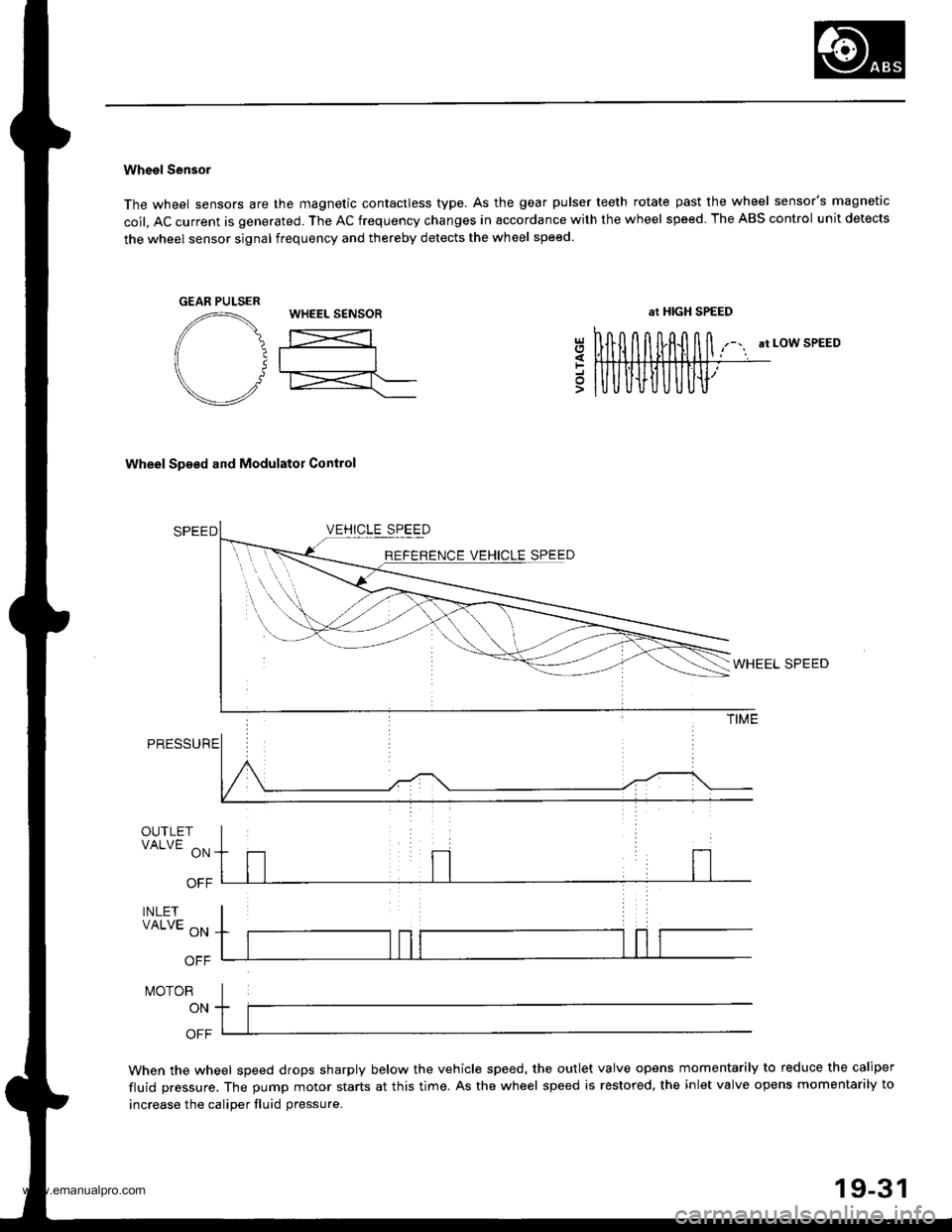
Wheel Sensor
The wheel sensors are the magnetic contactless type. As the gear pulser teeth rotate past the wheel sensor's magnetic
coil, AC current is generated. The AC frequency changes in accordance with the wheel speed. The ABS control unit detects
the wheel sensor signal frequency and thereby detects the wheel speed
at LOW SPEED
wheel Sp€od and Modulatot Control
VEHICLE SPEED
VEHICLE SPEED
WHEEL SPEED
PRESSU
OUTLETVALVE ON
OFF
INLETVALVE ON
OFF
MOTOR
ON
OFF
When the wheel speed drops sharply below the vehicle speed, the outlet valve opens momentarily to reduce the caliper
fluid pressure. The pump motor starts at this time. As the wheel speed is restored. the inlet valve opens momentarily to
increase the caliDer fluid oressure.
F
GEAR PULSER
19-31
www.emanualpro.com
Page 1100 of 1395
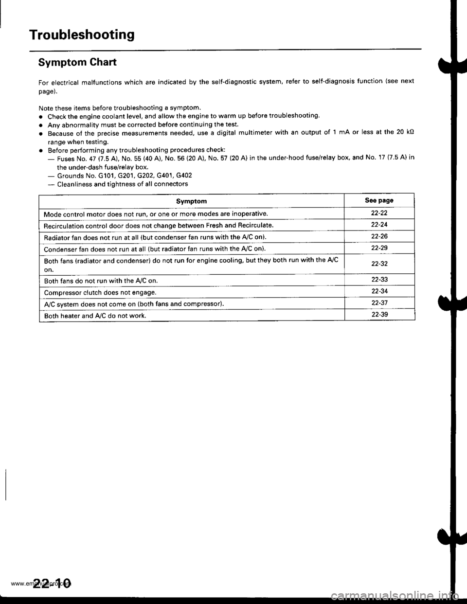
Troubleshooting
Symptom Ghart
For electrical malfunctions which are indicated by the self-diagnostic system, reter to selt-diagnosjs function (see next
page).
Note these items before troubleshooting a symptom.
. Check the engine coolant level, and allow the engine to warm up before troubleshooting.
. Anv abnormality must be corrected before continuing the test.
. Because of the precise measurements needed, use a digital multimeter with an output of 1 mA or less at the 20 kO
range when testing.
. Before performing any troubleshooting procedures check:
- Fuses No. 47 17.5 AJ, No. 55 (40 A), No. 56 (20 A), No. 57 (20 A) in the under-hood fuse/relay box, and No. 17 {7.5 A) in
the under-dash fuse/relay box.._ Grounds No. G101, G201, G202, G401, G4O2
- Cleanliness and tightness of all connectors
SymptomSse pags
Mode control motor does not run, or one or more modes are inoperative.
Recirculation control door does not change between Fresh and Recirculate.22-24
Radiator fan does not run at all (but condenser fan runs with the AVC on).
Condenser fan does not run at all {but radiator fan runs with the Ay'C on).22-29
Both fans (radiator and condenser) do not run for engine cooling. but they both run with the A,/C
on.
Both fans do not run with the Ay'C on22-33
Compressor clutch does not engage.22-34
AJC svstem does not come on (both fans and compressor).22-37
Both heater and A/C do not work,22-39
22-10
www.emanualpro.com