cut relay HONDA CR-V 1997 RD1-RD3 / 1.G Workshop Manual
[x] Cancel search | Manufacturer: HONDA, Model Year: 1997, Model line: CR-V, Model: HONDA CR-V 1997 RD1-RD3 / 1.GPages: 1395, PDF Size: 35.62 MB
Page 55 of 1395

Starting System
Starter Test
NOTE: The air temperature must be between 59 and'100'F (15 and 38"C) before testing.
Recommended Procedure:
. Use a staner system tester.
. Connect and operate the equipment in accordance
with the manufacturer's instructions.
. Test and troubleshoot as described.
Alte.nate Procedure:
. Use the following equipment:- Ammeter, 0 - 400 A- Voltmeter, 0 - 20 V (accurate within 0.1 volt)
Tachometer,0 - 1,200 rpm
. Hook up a voltmeter and ammeter as shown.
NOTE: After this test, or any subsequent repair. reset
the ECM/PCM to clear any codes (see section 1 1).
Check the Starter Engagement:
'1. Remove the No. 44 (15 A) fuse from the under-hood
fuse/relay box.
2. Turn the ignition switch to START (lll) with the shift
lever in E or E position (A/T) or with the clutch
pedal depressed {M/T). The starter should crank the
eng ine.
. lf the starter does not crank the engine, go to
step 3.
. lf it cranks the engine erratically or too slowly, go
to "Check for Wear and Damage" on the next
page.
NEGATIVE TERMINAL
4.
5.
6.
7.
8.
Check the battery, battery positive cable, ground.
staner cut relay, and the wire connections for loose-
ness and corrosion. Test again.
lf the staner still does not crank the engine, go to
step 4.
Unplug the connector (BLK /VHT wire and solenoid
terminal) from the starter.
Connect a jumper wire from the baftery positive (+)
terminal to the solenoid terminal.
The starter should crank the engine.
. lf the starter still does not crank the engine,
remove it, and diagnose its internal problem.
. lf the starter cranks the engine, go to step 6.
Check the ignition switch (see section 23).
Check the starter cut relay {see section 23}.
Check the IVT gear position switch (A/T) or the clutch
interlock switch (M[).
Check for an open in the wire between the ignition
switch and starter.
(cont'd)
4-5
www.emanualpro.com
Page 282 of 1395

PGM-FI System
System Description
INPUTS
CKP/TDC/CYP Sensor
CKF Sensor
MAP Sensor
ECT Sensor
IAT Sensor
TP Sensor
Primary HO2S
Secondary H02S
vss
KS*5
BARO Sensor
ELD*6
Starter Signal
ALT FR Signal
Air Conditioning Signal
Ay'T Gear Position Signal*1
Baftery Voltage (lGN.1)
Brake Switch Signal
PSP Switch Signal
Fuel Tank Pressuae Sensor*4. *5
Countershaft Speed Sensor*1
Mainshaft Speed Sensor*r
OVER-DRIVE Switch Signal*s
ENGINE CONTROL MODULE (ECM)/
POWERTRAIN CONTROL MODULE (PCM) OUTPUTS
|iuel 1"j""- Th,rhg ""d Drrafr";-l
Et*-.nt"tdt"cont.orl
to,r*,c;;trffi;]
l.----.---:. .Lrgnrnon |lmrng Lonrror I
Ecir/PcM B*k',p Fr""il]
m;"t-ll-r*'io*l
Fuel Injectors
PGM-Fl Main Relay (Fuel Pump)
MIL
IAC Valve
Ay'C Compressor Clutch Relay
Radiator Fan Relay
Condenser Fan Relay
ALT
tcM
EVAP Purge Control Solenoid
Valve
Primary HO2S Heater
Secondary H02S HeaterEVAP Bypass Solenoid Valve*a *5
EVAP Control Canister Vent Shut
DLC
Lock-up Control Solenoid Valve*l
Shift Control Solenoid Valve*1
Ay'T Clutch Pressure Control
Solenoid Valve*1
D4 Indicator Light'1 *3, *a
D Indicator Light,l *5
OVER-DRIVE OFF Indicator
Lighl*t *:
*1: A/T {3:'97 model'2: M/f +4:'98 model*5: '99 - 00 models"6: USA
PGM-Fl System
The PGM-Fl system on this model is a sequential multiport fuel injection system.
Fuel iniecior Timing and Duration
The ECM/PCM contains memories for the basic discharge durations at various engine speeds and manifold pressure. The
basic discharge duration, after being read out from the memory, is further modified by signals sent from various sensors
to obtain the final discharge duration.
ldle Air Control
ldle Air Control Valve (lAC Valve)
When the engine is cold, the Ay'C compressor is on, the transmission is in gear, the brake pedal is depressed, the P/S load
is high, or the alternator is charging, the ECM/PCM controls current to the IAC Valve to maintain the correct idle speed.
lgnition Timing Control
o The ECM/PCM contains memories for basic ionition timing at various engine speeds and manifold air flow rates.
lgnition timing is also adjusted for engine coolant temperature.
. A knock control system was adopted which sets the ideal ig nition timing for the octane rating of the gasoline used.*s
Other Control Funstions
1. Starting Control
When the engine is started. the ECM/PCM provides a rich mixture by increasing fuel injector duration.
2. Fuel Pump Control
. When the ignition switch is initially turned on (ll). the ECMiPCM suppli€s ground to the PGM-FI main relay that
supplies current to the fuel pump for two seconds to pressurize the fuel system.
. When the engine is running, the ECM/PCM supplies ground to the PGM-FI main relay that supplies current to the
fuel oumo.
. When the engine is not running and the ignition is on, the ECM/PCM cuts ground to the PGM-FI main relay which
cuts current to the fuel pump.
1 1-80
www.emanualpro.com
Page 380 of 1395
Fuel Supply System
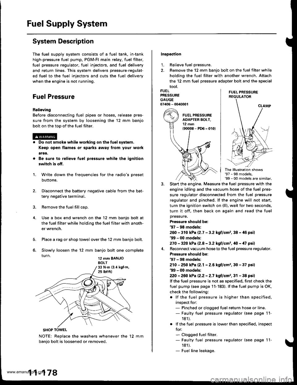
System Description
The fuel supply system consists of a fuel tank, in-tank
high-pressure fuel pump. PGM-Fl main relay, fuel filter,
fuel pressure regulator, fuel injectors, and fuel delivery
and return lines. This system delivers pressure-regulat-
ed fuel to the fuel injectors and cuts the fuel delivery
when the engine is not running.
Fuel Pressure
Relieving
Before disconnecting fuel pipes or hoses, release pres-
sure from the system by loosening the 12 mm banjo
bolt on the too of the fuel filter.
Do not smoke while working on the fuel system.
Ke€p open flames or sparks away from your work
area,
Be sure to relieve fuel pressure while the ignition
switch is off.
Write down the frequencies for the radio's preset
buttons.
Disconnect the battery negative cable from the bat-
tery negative terminal.
Remove the fuel fill cap.
Use a box end wrench on the 12 mm banjo bolt at
the fuel filter while holding the fuel filter with anoth-
er wrench.
Place a rag or shop towel over the '12 mm banjo bolt.
Slowly loosen the 12 mm banjo bolt one complete
rurn 12 mm BANJoBOLT
1.
SHOP TOWEL
NOTE: Replace the washers whenever the 12 mm
banio bolt is loosened or removed.
11-178
Inspection
1, Relieve fuel pressure.
2. Remove the 12 mm banjo bolt on the fuel filter while
holding the fuel filter with another wrench. Attach
the 12 mm fuel pressure adapter bolt and the special
tool.
FUEL PRESSUREREGULATON
FUELPRESSUREGAUGE07406 - 0040001
The illustration shows'97 - 98 models,'99 - 00 models are similar.
Start the engine. Measure the fuel pressure with the
engine idling and the vacuum hose of the fuel pres-
sure regulator disconnected from the fuel pressure
regulator and pinched. lf the engine will not start,
turn the ignition switch on (ll), wait for two seconds,
turn it off, then back on again and read the fuel
pressure.
Pressure should be:'97 - 98 mod€ls:
260 -31O kPa 12.7 - 3.2 kgf/cm,, 38 - 46 psil'99 - 0O models:
270 - 32O kPa Q.A - 3.2 kgf/cm'�, ifo - /U psil
Reconnect vacuum hose to the fuel pressure regulator.
Prgs3ure should be:'97 - 98 models:
210 - 25O kPa 12.1- 2.6 kgf/cm'�, 30 - 37 psi)'99 - 00 models:
22O -26iJ kPa 12.2 - 2.7 kgt/cm'�, 31 - 38 psi)
lf the fuel pressure is not as specified, first check the
fuel pump (see page 11- 183). lf the fuel pump is OK,
check the following:
. lf the fuel pressure is higher than specified,
inspect for:- Pinched or clogged fuel return hose or line.- Faulty fuel pressure regulator (see page 11-
181).
. lf the fuel pressure is lower than specified. inspect
for:- Clogged fuel filter.- Faulty fuel pressure regulator (see page 11-
1811.- Fuel line leakage.
www.emanualpro.com
Page 1130 of 1395
Troubleshooting
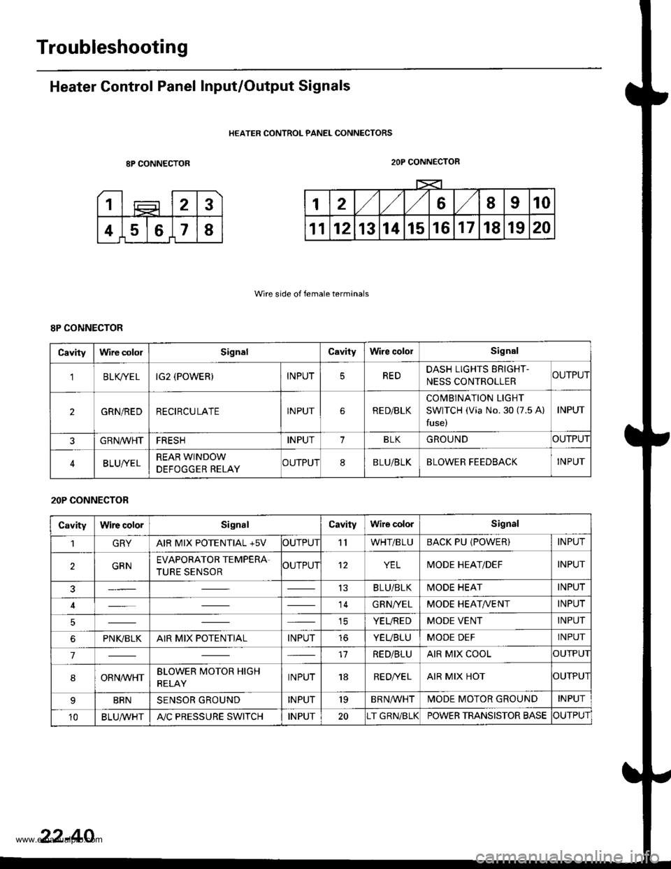
Heater Control Panel Input/Output Signals
HEATER CONTROL PANEL CONNECTORS
8P CONNECTOR
Wire side of female terminals
2OP CONNECTOR
8P CONNECTOR
Cavitylrvire cololSignalCavityWire cololSignal
'lBLK/TE LIG2 (POWER)INPUTREDDASH LIGHTS ERIGHT-
NESS CONTROLLERCUTPUT
2GRN/REDRECIRCULATEINPUTRE D/BLK
COMBINATION LIGHT
SWITCH (Via No. 30 (7.5 A)
fuse)
INPUT
GRN/VVHTFRESHINPUT1BLKGROUNDOUTPUT
BLUI/ELREAR WINDOW
DEFOGGER RELAYCUTPUT8BLU/BLKBLOWER FEEDBACKINPUT
20P CONNECTOR
CavityWire colorSignalCavityWire colorSignal
1GRYAIR MIX POTENTIAL +5VOUTPUT'llWHT/BLUBACK PU (POWER)INPUT
2GRNEVAPORATOR TEMPERA.
TURE SENSOROUTPUT12YELMODE HEAT/DEFINPUT
13BLU/BLKMODE HEATINPUT
14GRN/YELMODE HEAT/VENTINPUT
ICYEUREDMODE VENTINPUT
6PNI(BLKAIR MIX POTENTIALINPUTtoYEUBLUMODE DEFINPUT
717RED/BLUAIR MIX COOLOUTPUI
8ORNrur'HTBLOWER MOTOR HIGH
RELAYINPUT18RE D/VE LAIR MIX HOTOUTPUI
BRNSENSOR GROUNDINPUT'19BRNA/VHTIVIODE MOTOR GROUNDINPUT
10BLU,ryVHTA"/C PRESSURE SWITCHINPUT20T GRN/BLKPOWER TRANSISTOR BASECUTPUT
22-40
www.emanualpro.com
Page 1169 of 1395
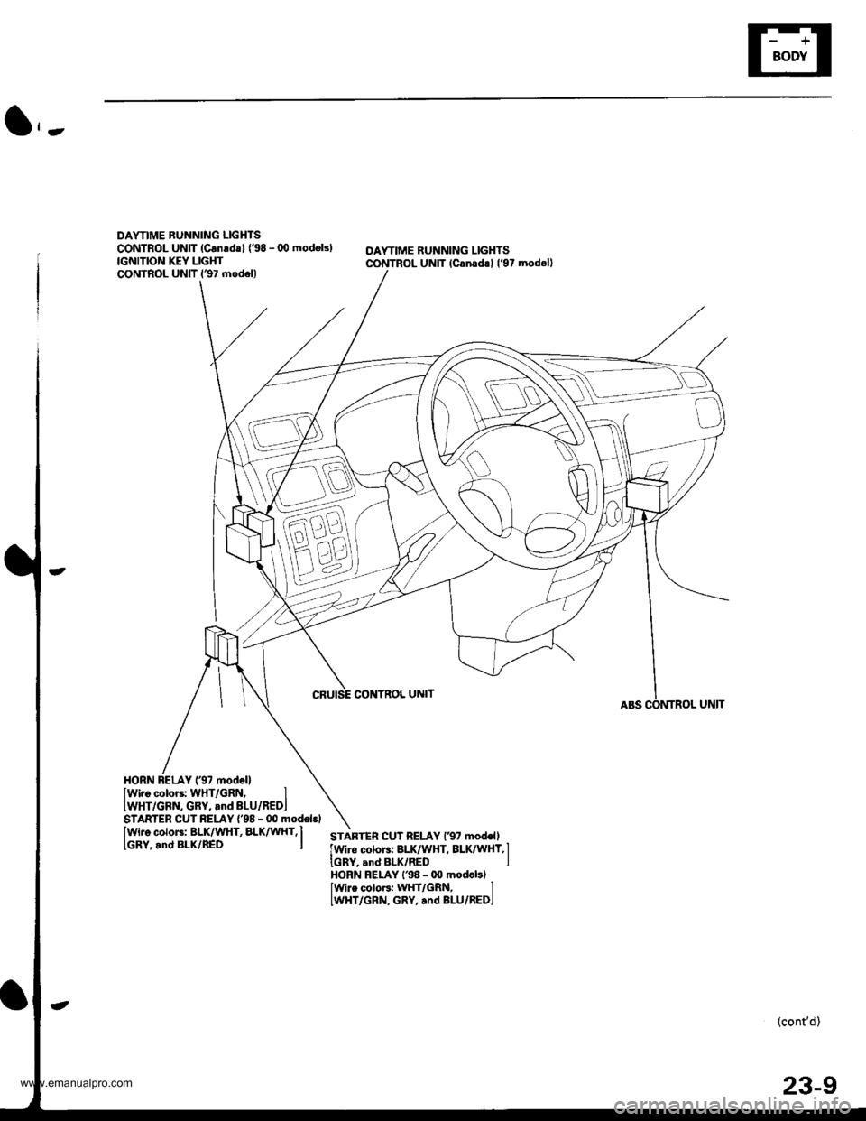
DAYTIME BUNNING LIGHTSCONTROL UNIT (Canrda) {'98 - (X) modok)IGNITION KEY LIGHTCONTROL UNIT l€7 model)
OAYTIME RUNNING LIGHTSCONTROL UNIT lcanad!l l'97 modell
CRUISE CONTNOL UNIT
HORN BELAY 137 modellIwiro color3: WHT/GRN, IIWHT/GBN, GRY, and BLU/REDI
IWir6 color3: BLK/WHT, BLK^ UHT,I
lGRY,.nd BLx/nED I
STARTER CUT RELAY {'98 - 00 modelsl
STARTEn CUT RELAY l€7 mod€ll
lwire colors: BLK/WHT, BLK/WHY,l
IGRY, and BLK/RED IHORN FELAY l'98 - 00 modcb)lwire coloF: WHT/GRN, lLWHT/GRN, GRY, and BLU/REDI
{cont'd)
23-9
www.emanualpro.com
Page 1180 of 1395

Connector ldentification and Wire Harness Routing
Main Wire Harn€ss (left side of dash and floor branchesl {cont,dl
c401
c402
c403
c404
c404
c405
c406
c407
c408
c409
c410
c410
c411
c412
c413
c413
c414
c415
c416
c416
c417
c418
c419
c420
c420
c421
c422
c423
c424
c425
c42A
c426
c437
c438
c438
c439
c440
c441c442
5
20
20
24
't4
8
5
3
12
10'1
18
20'18
10
15
1
4
8
5
5
22
Behind left kick panel
Behind left kick panel
Behind left kick panel
Behind left kick panel
Behind left kick panel
Under left side of dashUnder left side of dashUnder left side of dashUnder left side of dashUnder left side of dashUnder left side of dashUnder left side of dash
Under left side of dashUnder left side of dashUnder left side of dash
Under left side of dash
Under left side of dashUnder left side of dashUnder left side of dashUnder left side of dashUnder left side of dashUnder left side of dashUnder left side of dashUnder left side of dash
Under left side of dashUnder left side of dashUnder left side of dashUnder middle of dashUnder middle of dashUnder middle of dashUnder middle of dashUnder middle of dash
Under left side of dashUnder left side of dash
Under left side of dashUnder left side of dashUnder left side of dashUnder left side of dashUnder left side of dash
Under left side of dash
Under left side of dashUnder left side of dashUnder left side of dashUnder left side of dash
Starter cut relay
Horn relay
Left side wire harness (C558)
Left side wire harness (C559)
Left side wire harness (C559)
Cruise control unitDaytime running lights control unitDaytime running lights control unitlgnition key light control unitInterior wire harness {C701)Cable reel
Cable reel
lgnition key switchlgnition key switch
Combination switch sub-harness {C753)
Combination switch sub-harness (C753)
SRS main harness (C803)
Dashboard wire harness (C503)
Dashboard wire harness (C501)
Dashboard wire harness {C501)Under-dash fuse/relay box (C922)
Under-dash fuse/relay box (C920)
Under-dash fuse/relay box (C919)
lntegrated control unit
Integrated control unitFront fog lights switchBrake switch
Interlock control unitReverse relay
Rear accessory socket relayRear accessory socket relayRear heated oxygen sensor sub-harness (C722)
Security control unitSecurity starter cut relay (for securityalarm system)
Junction connector (for interlock system)Security wire harnessSecurity wire harnessRear window wiper control unitCombination switch sub-harness (C760)
Combination switch sub-harness (C760)
Securlty indicatorSecurity valet switchClutch interlock switchClutch switch (for cruise control)
'97 model'98 - 00mooets
Canada
Canada'97 model
'97 model'98 - 00models
'97 - 98models'99 - 00
moqets
'97 model'98 - 00mooets
Optional
Optional
Optional
Optional
Optional'97 model
'97 - 98mooels'99 - 00models
OptionalOptional
Mfi
Mlr
Under left side of dashBody ground, via main wire harness
23-20
www.emanualpro.com
Page 1213 of 1395
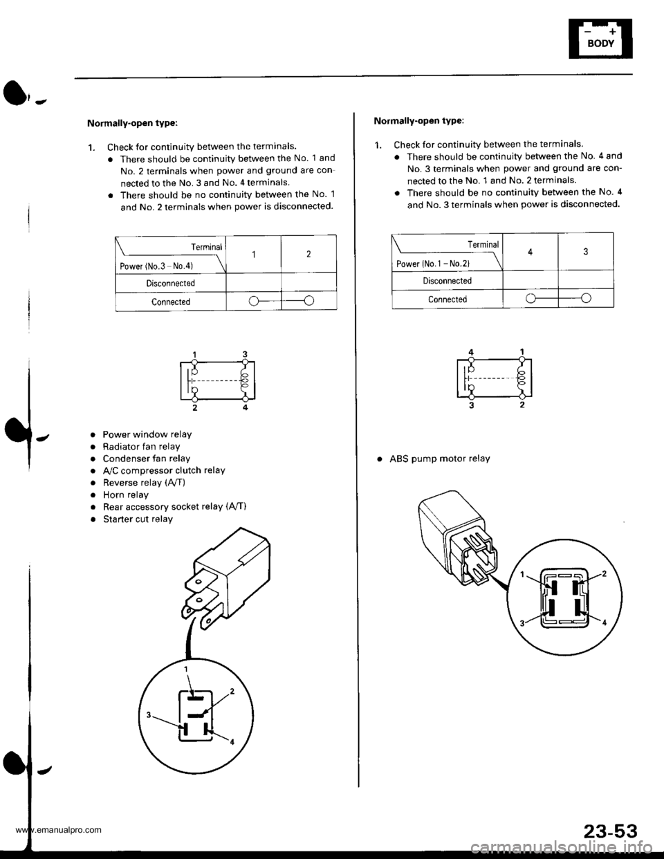
Normally-open type:
1. Check for continuity between the terminals.
. There should be continuity between the No. 1 and
No. 2 terminals when power and ground are con
nected to the No. 3 and No. 4 terminals
. There should be no continuitv between the No. 1
and No. 2 terminals when power is disconnected.
Terminal
t.*", ^"- t*f \
12
Drsconnected
Connectedoo
a
a
a
a
a
a
Power window relay
Radiator fan relay
Condenser fan relay
A,/C compressor clutch relay
Reverse relay (A/f)
Horn relay
Rear accessory socket relay {A,/T)
Starter cut relay
\K,
Normally-open type:
1. Check for continuity between the terminals.
. There should be continuity between the No. 4 and
No.3 terminals when power and ground are con-
nected to the No. 1 and No. 2 terminals.
. There should be no continuity between the No. 4
and No. 3 terminals when power is disconnected.
Terminal
tl**^-*
-_\3
Disconnected
Connectedo----o
. ABS pump motor relay
www.emanualpro.com
Page 1225 of 1395
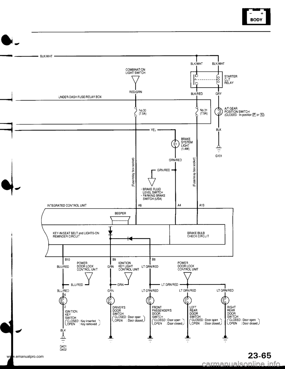
< - ELK/WHT
S'TARTEBCUTRELAY
A,/rGEARPOSrr 0N SWTTCH(CLOSED :ln postion Eor N)
COMBINATONLIGHT SWITCH
\-/
IRED/GRN
I
.l-
NTEGRATED CONTROL UNIT
POWERDOOR LOCKCONTROL UNIT
I B1o PowERBLU/RED DOOR LOCK
I CONTFOL UN T
IY
F r,r'tro J
BLUi RED
"l\
u/
llon. no*
155,1'*IaCLOSED Keylnseded
| \oPEN Key rcmoved
8LK
4
G40r
LTGRN/RED LTGRN/RED LTtl
/rh d[)v !s-l
I FFONT I LEFTI PASSENGEBS I REABI DOOR | 00ORoDen ) lSwlTcH I SWITCHdosedJ J f C-OSED : ooot ooer ) | f CLOSED : Door opel
| ( ooE Doot dosed,r | \oPEN Doo' closed
tl_L -._:-
1,,,,,"
Yilei'rGRN/RED
. BNAKE FLUIOLEVEL SWITCH.PARKING ERAKEswrTcH (usA)
A8
BRAKE BULBCHECKCIFCUTKEY.IN]SEAT BELT and LIGHTS'ONREMINDER C RCU T
23-65
www.emanualpro.com
Page 1230 of 1395
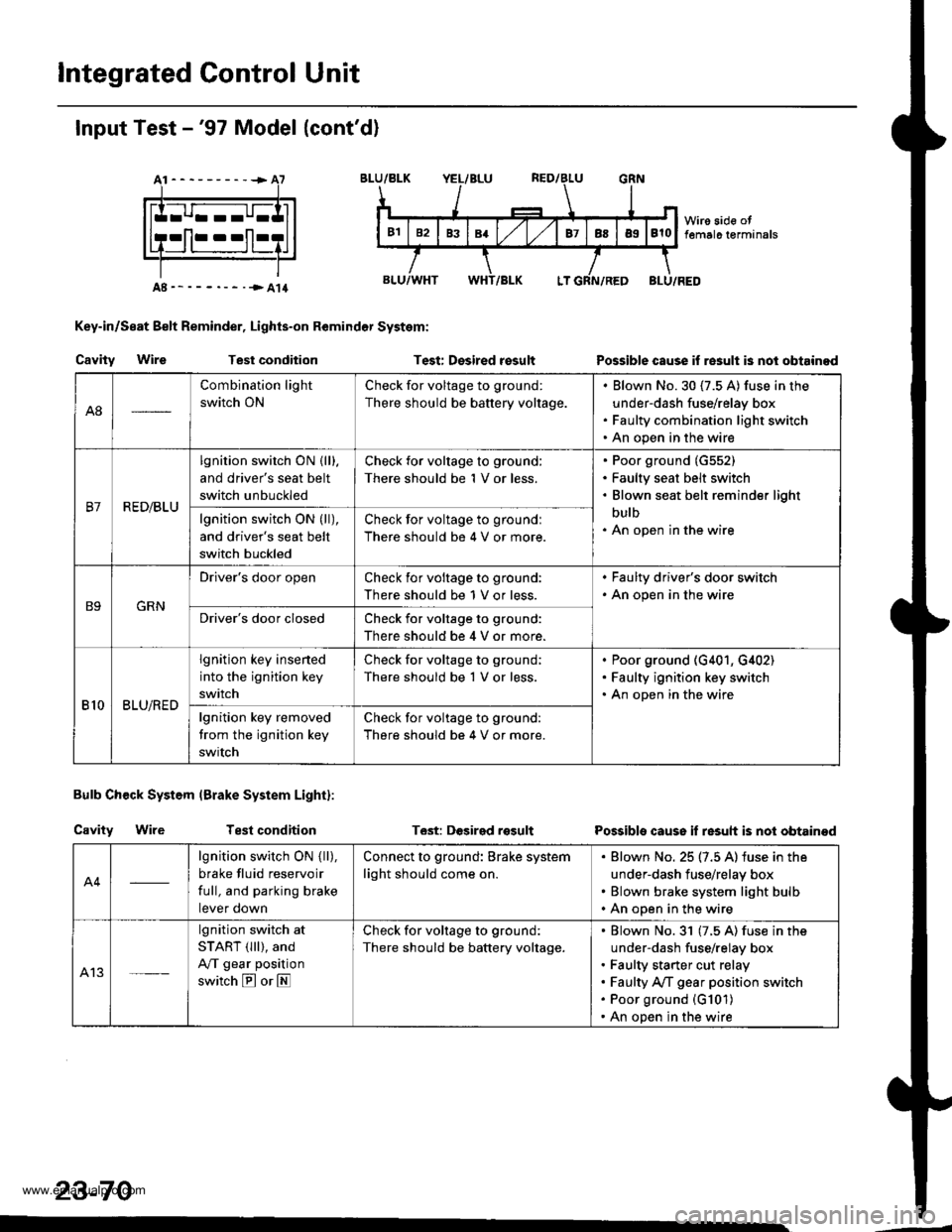
lntegrated Control Unit
Input Test -'97 Model (cont'd)
At----------+A7
Key-in/Seat Belt Reminder, Lights-on Remindor System:
Cavity WireTest conditionTest: Desired rosultPossible cause if re3ult is nol obtainod
Bulb Check System (Brake System Light):
Cavity WireTest conditionT6st: DGsirgd rosultPossible cause if resuh is not obtainod
23-70
A8
Combination light
switch ON
Check for voltage to ground:
There should be battery voltage.
Blown No.30 (7.5 A) fuse in the
under-dash fuse/relay box
Faulty combination light switch
An open in the wire
B7R ED/BLU
lgnition switch ON {lll.
and driver's seat belt
switch unbuckled
Check for voltage to ground:
There should be 1 V or less.
Poor ground (G552)
Faulty seat belt switch
Blown seat belt reminder light
bulb
An open in the wirelgnition switch ON (ll),
and driver's seat belt
switch buckled
Check for voltage to groundl
There should be 4 V or more.
B9GRN
Driver's door openCheck ior voltage to ground:
There should be 1 V or less.
. Faulty driver's door switch. An open in the wire
Driver's door closedCheck for voltage to ground:
There should be 4 V or more.
810BLU/RED
lgnition key insened
into the ignition key
switch
Check for voltage to ground;
There should be 1 V or less.
Poor ground (G401, G,[02)
Faulty ignition key switch
An open in the wire
lgnition key removed
trom the ignition key
swrtch
Check for voltage to ground:
There should be 4 V or more.
A4
lgnition switch ON { ll),
brake fluid reservoir
full, and parking brake
tever oown
Connect to ground: Brake system
light should come on.
Blown No. 25 (7.5 A) iuse in the
under-dash fuse/relay box
Blown brake system light bulb
An open in the wire
A13
lgnition switch at
START (lll), and
A/T gear position
switch E or E
Check for voltage to ground:
There should be battery voltage.
Blown No.31 (7.5 A) fuse in the
under-dash fuse/relay box
Faulty starter cut relay
Faulty A/f gear position switch
Poor ground (G101)
An open in the wire
www.emanualpro.com
Page 1234 of 1395
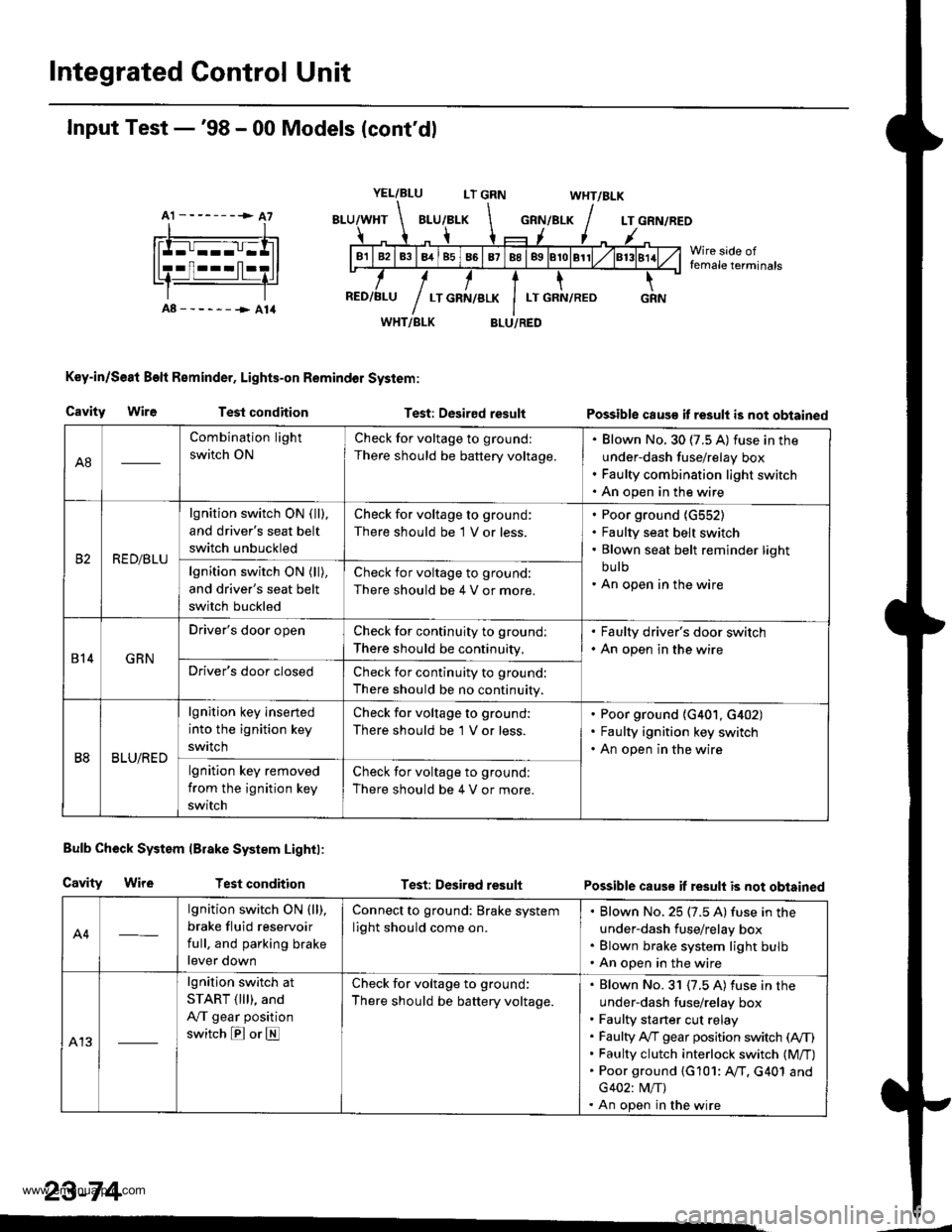
Integrated Control Unit
A1 --------> A7
Input Test -'98 - 00 Models (cont'dl
YEL/BLULT GRNWHT/BLK
GRN/BLKLT GRN/REO
Wire side offemale terminals
A8------->A14WHT/BLK
Key-in/Se8t Beft Reminder, Lights-on Remindol System:
BLU/RED
Cavity WireTest conditionTest: Desired resultPossible caus€ it result is not obtained
Bulb Check System lBrake System Lightl:
Cavity WireTest conditionTest: Desired resultPossible caus€ if result is not obtained
A4
lgnition switch ON (ll),
brake fluid reservoir
full, and parking brake
lever down
Connect to ground: Brake system
light should come on.
Blown No. 25 (7.5 A) fuse in the
under-dash fuse/relay box
Blown brake system light bulb
An open in the wire
A13
lgnition switch at
START ( lll), and
A,/T gear position
switch E or E
Check for voltage to ground:
There should be battery voltage.
Blown No. 31 {7.5 A) fuse in the
under-dash fuse/relay box
Faulty sta rter cut relay
Faulty A,/T gear position switch (A,/T)
Faulty clutch interlock switch (M/T)
Poor ground {G101: AfI. G401 and
G402: M/T)
An open in the wire
23-74
A8
Combination light
switch ON
Check for voltage to ground:
There should be battery voltage.
Blown No. 30 (7.5 A) fuse in the
under-dash fuse/relay box
Faulty combination light switch
An open in the wire
RED/BLU
lgnition switch ON ( ll),
and driver's seat belt
switch unbuckled
Check for voltage to ground:
There should be 1 V or less.
Poor ground {G552)
Faulty seat belt switch
Blown seat belt reminder light
bu lb
An open in the wirelgnition switch ON (ll),
and driver's seat belt
switch buckled
Check for voltage to ground:
There should be 4 V or more.
814GRN
Driver's door openCheck for continuity to ground:
There should be continuity,
. Faulty driver's door switch. An open in the wire
Driver's door closedCheck for continuity to ground:
There should be no continuity.
B8BLU/RED
lgnition key inserted
into the ignition key
swrtch
Check for voltage to ground:
There should be 'l V or less.
Poor ground (G401, G402)
Faulty ignition key switch
An open in the wire
lgnition key removed
from the ignition key
switch
Check for voltage to ground:
There should be 4 V or more.
www.emanualpro.com