front bumper removal HONDA CR-V 1997 RD1-RD3 / 1.G Workshop Manual
[x] Cancel search | Manufacturer: HONDA, Model Year: 1997, Model line: CR-V, Model: HONDA CR-V 1997 RD1-RD3 / 1.GPages: 1395, PDF Size: 35.62 MB
Page 982 of 1395
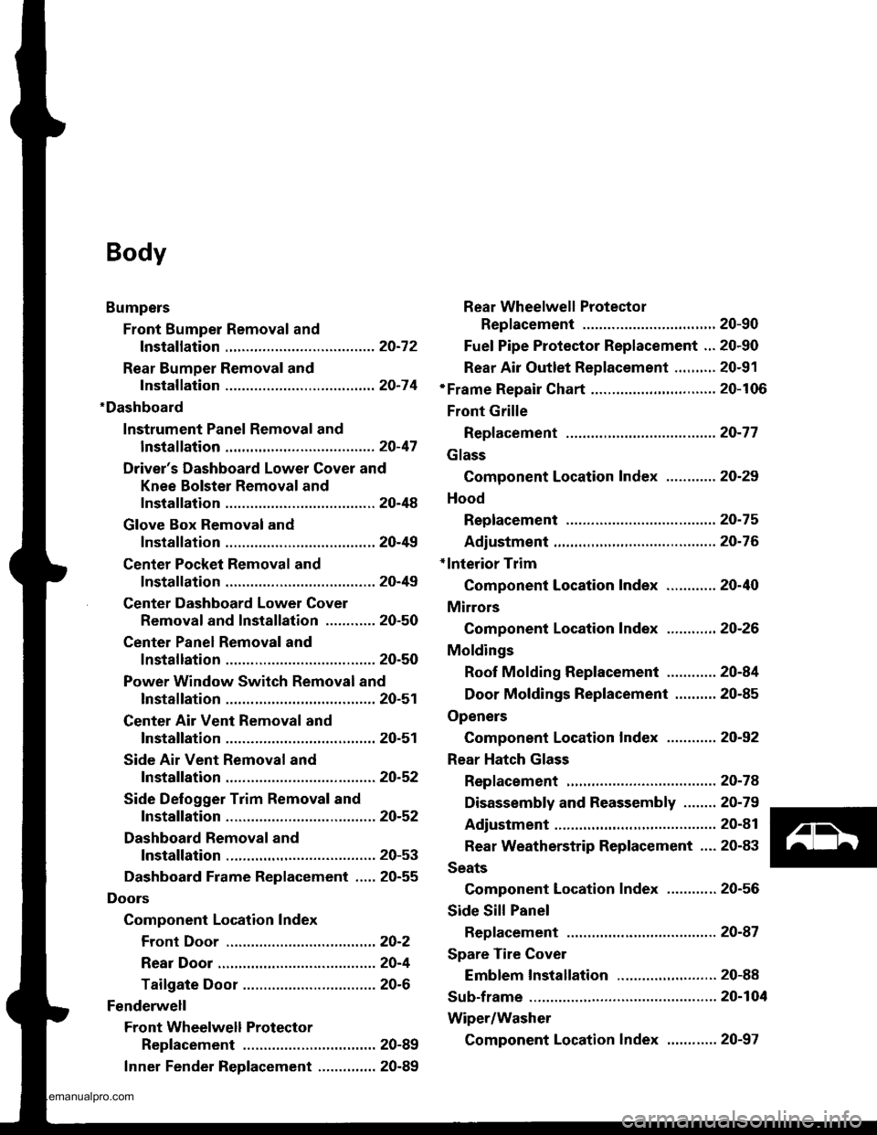
Body
Bumpers
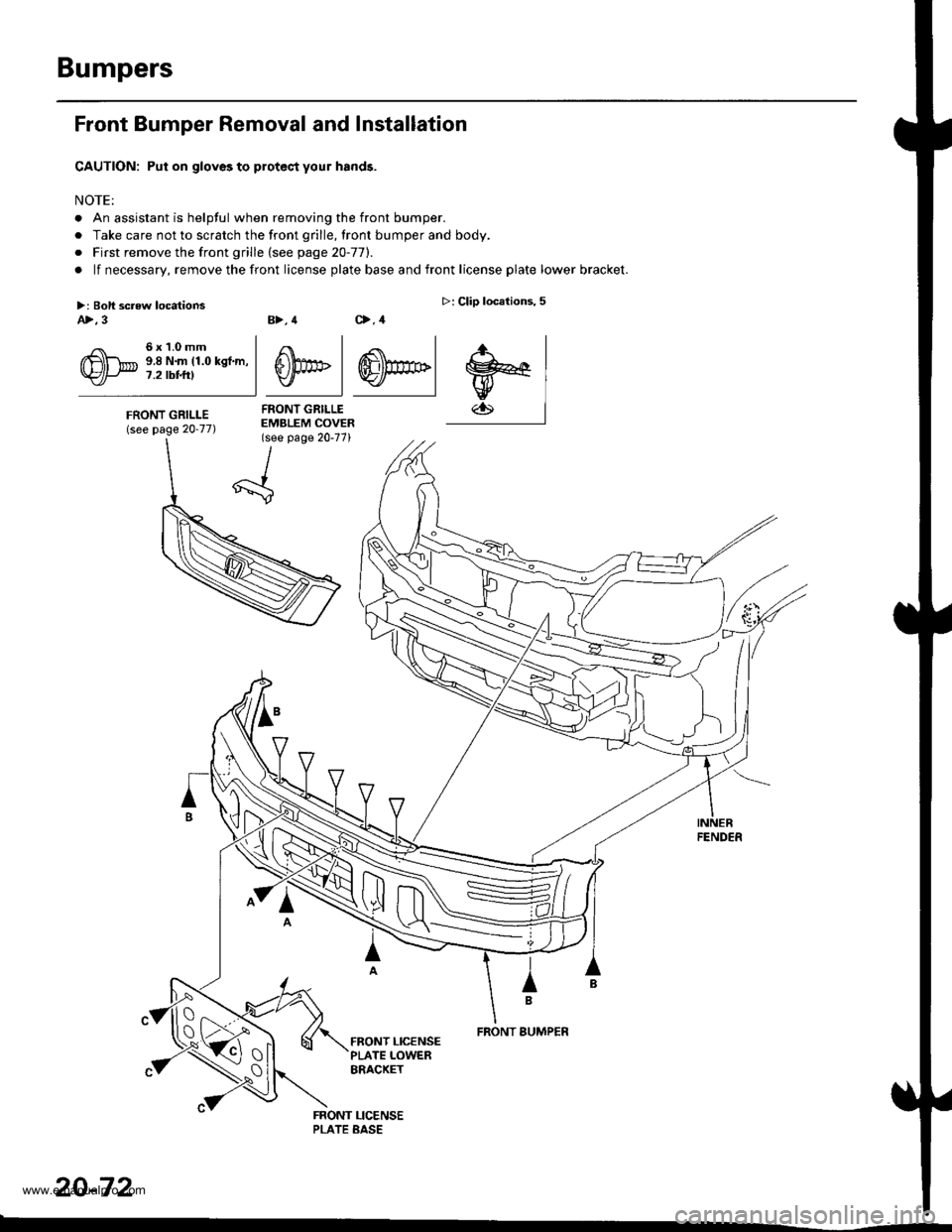
Front Bumper Removal and
fnstaflation .........20-72
Rear Bumper Removal and
fnstaflation .........20-74
'Dashboard
lnstrument Panel Removal and
lnstallation .........20-47
Driver's Dashboard Lower Cover and
Knee Bolster Removal and
Installation .........20-48
Glove Box Removal and
lnstallation .........20-49
Center Pocket Removal and
lnstallation .........20-49
Center Dashboard Lower Cover
Removal and lnstallation ............ 20-50
Center Panel Removal and
lnstallation .........20-50
Power Window Switch Removal and
lnstallation .........20-51
Center Air Vent Removal and
lnstallation .........20-51
Side Air Vent Removal and
fnstallation .........20-52
Side Defogger Trim Removal and
fnstallation .........20-52
Dashboard Removal and
lnstallation .........20-53
Dashboard Frame Replacement ..... 20-55
Doors
Component Location Index
Front Door ,,...,,,,20-2
Rear Door ...........20-4
Tailgate Door ................................ 20-6
Fenderwell
Front Wheelwell Protector
Replacement .....20-89
Inner Fender Replacement .,.....,.,.... 20-89
Rear Wheelwell Protectol
Replacement .....20-90
Fuel Pipe Protector Replacement ... 20-90
Rear Air Outlet Replacement .......... 20-91
*Frame Repair Chart .............................. 20-106
Front Grille
Repf acement .........20-77
Glass
Component Location Index ............ 20-29
Hood
Replacement ......,,,20-75
Adjustment ............20-76
*lnterior Trim
Component Location Index ............ 20-40
Mirrors
Component Location Index .........,,, 20-26
Moldings
Roof Molding Replacement ............ 20-84
Door Moldings Replacement .......... 20-85
Openers
Component Location Index ............ 20-92
Rear Hatch Glass
Replacement .........20-74
Disassembly and Reassembly ........ 20-79
Adiustment ............20-81
Rear Weatherstrip Replacement .... 20-83
Seats
Component Location Index ............ 20-56
Side Sill Panel
Repfacement .........20-87
Spare Tire Cover
Emblem Installation ........................ 20-88
Sub-frame ..................20-104
Wiper/Washer
Component Location lndex ,,,,,....... 20-97
www.emanualpro.com
Page 1053 of 1395
Bumpers
Front Bumper Removal and Installation
CAUTION: Put on gloves to protec,t your hands.
NOTE:
. An assistant is helpful when removing the front bumper.
. Take care not to scratch the front grille, lront bumper and body.
o First remove the front grille (see page 20-77).
. lf necessary, remove the front license plate base and front license plate lower bracket.
B>, 4 C>,4
4 .<\l
S))PF | ffi)m>lv I Y./ |
FRONT GRILLEEMBLEM COVER(see page 20-77)
>: Clip locations,5
.r., I
w€lw
FENDER
IB
FRONT BUMPER
20-72
>: Boli screw locationsA>,3
6x1.0mm9.8 N.m (1.0 kgf.m,7.2 tbt t0
FRONT GRILLE(see page 20-77)
tx -
\{_:
www.emanualpro.com
Page 1054 of 1395
A>, 5 V.2
>: Clip locationsA>, 5 B>.3
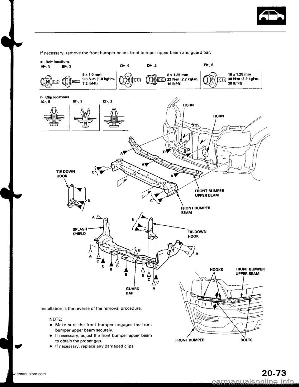
lf necessary, remove the front bumper beam, front bumper upper beam and guard bar.
>: Boh locationsc>.6D>,2E>,6
TIE DOWNHOOK
Yl- r
{to/
Installation is the reverse ot the removal procedure.
NOTE:
. Make sure the front bumper engages the front
bumper upper beam securely.
. It necessary, adjust the front bumper upper beam
to obtain the proper gap.
. lf necessary, replace any damaged clips.
Gfu @p;i,li',ll-"-'
TIE.DOWNHOOK
v1
10 x 1.25 mm38 N.rn {3.9 kgf.m,28 rbl.ftl
@,,2
nln-nlznr I
dE6 I #\Er+ | ;lHl= |€ =.=r t:Wl
BEAM
FRONT BUMPEB
20-73
www.emanualpro.com
Page 1070 of 1395
Fenderwell
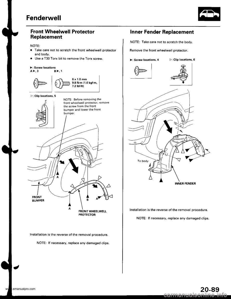
Front Wheelwell Protector
Replacement
NOTE:
a Take care not to scratch the front wheelwell protector
and body.
. Use a T30 Torx bit to remove the Torx screw.
>: Screw locationsa >,3
/\l
6'thp IY/
>: Clip locations,
AI
4t I
wt I
al
B>, 1
,,-C\
s)Dv.l/
6x1.0mm9.8Nm(1.0kgf.m,7.2 tbf.ft)
NOTE: Before temoving thefront wheelwell Protector, remove
the screw from the front
bumper and lower the front
bumper.
Installation is the reverse of the removal Drocedure.
NOTE: lf necessary, replace any damaged clips.
Inner Fender Replacement
NOTE: Take care not to scratch the body.
Remove the front wheelwell protector,
>: Screw locations, 4
Installation is the reverse of the removal procedure.
NOTE; lf necessary, replace any damaged clips.
>: Clip locations,
ffi)fl(
l#:rl
A\
s))pp>Y]
INNER FENDER
20-89
www.emanualpro.com
Page 1080 of 1395
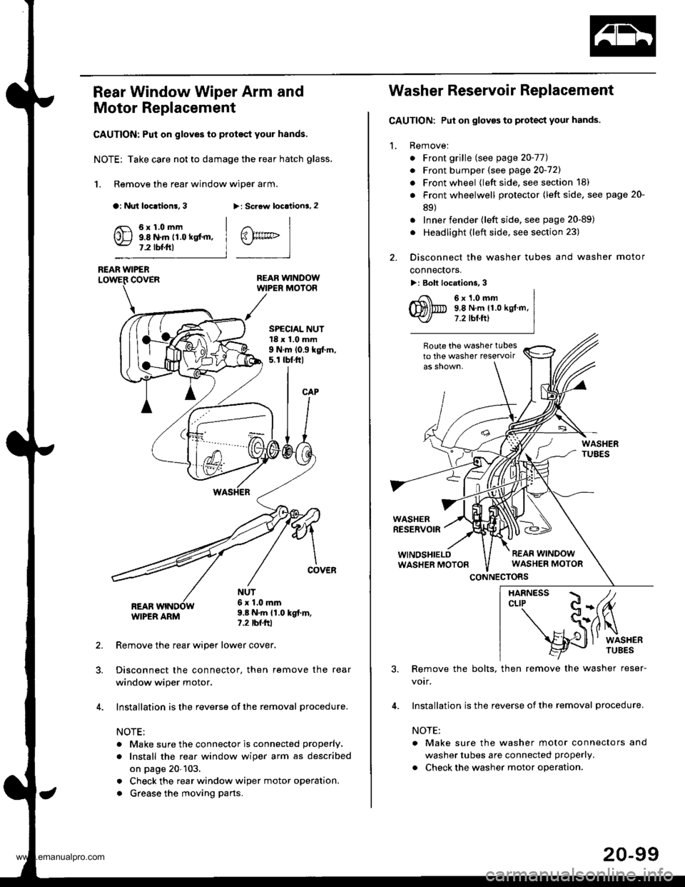
Rear Window Wiper Arm and
Motor Replacement
CAUTION: Put on gloves to protect your hands.
NOTE; Take care not to damage the rear hatch glass.
1. Remove the rear window wiper arm.
a: Nut loc.tion!, 3>: Scaow locationa, 2
REAR WINDOWWIPER MOIOR
REAR WIPERCOVER
REARWIPER ARM
6x1.0mm9.8 N.m 11.0 kgt'm,7.2 tbf.ftl
SPECIAL NUT18 x 1.0 mm9 N.m 10.9 kgt m,5. r tbt.ftl
NUT6x 1.0mm9.8 N.m {1.0 kgt.m,?.2 tbfftl
Remove the rear wiper lower cover.
Disconnect the connector, then remove the rear
window wiper motor.
Installation is the reverse of the removal procedure.
NOTE:
. Make sure the connector is connected properly.
. Install the rea. window wiper arm as described
on page 20-103.
. Check the rear window wiper motor operation.
. Grease the moving parts.
@rrc
Washer Reservoir Replacement
GAUTION: Put on gloves to protect your hands.
1. Remove:
. Front grille (see page 20-771
. Front bumper (see page 20-721
. Front wheel {left side, see section 18)
. Front wheelwell protector (left side, see page 20-
89)
. Inner fender (left side, see page 20-89)
. Headlight (left side, see section 23)
2. Disconnect the washer tubes and washer motor
connectors.
>: Bolt locations, 3
6x1.0mm9,8 N.m 11.0 kgt.m,7.2 tbt.ftl
Route the washer tubesto the washer teservoir
WASHERRESERVOIR
WINOSHIELOWASHER MOTON
CONNECTORS
3. Remove the bolts, then remove the washer reser-
votr,
4. Installation is the reverse of the removal procedure.
NOTE:
a Make sure the washer motor connectors and
washer tubes are connected properly.
. Check the washer motor operation.
HARNESS / tcLrP C-(fu
- S(ilq
s{J
l' wrsHER
20-99
www.emanualpro.com