jump start HONDA CR-V 1997 RD1-RD3 / 1.G Workshop Manual
[x] Cancel search | Manufacturer: HONDA, Model Year: 1997, Model line: CR-V, Model: HONDA CR-V 1997 RD1-RD3 / 1.GPages: 1395, PDF Size: 35.62 MB
Page 55 of 1395

Starting System
Starter Test
NOTE: The air temperature must be between 59 and'100'F (15 and 38"C) before testing.
Recommended Procedure:
. Use a staner system tester.
. Connect and operate the equipment in accordance
with the manufacturer's instructions.
. Test and troubleshoot as described.
Alte.nate Procedure:
. Use the following equipment:- Ammeter, 0 - 400 A- Voltmeter, 0 - 20 V (accurate within 0.1 volt)
Tachometer,0 - 1,200 rpm
. Hook up a voltmeter and ammeter as shown.
NOTE: After this test, or any subsequent repair. reset
the ECM/PCM to clear any codes (see section 1 1).
Check the Starter Engagement:
'1. Remove the No. 44 (15 A) fuse from the under-hood
fuse/relay box.
2. Turn the ignition switch to START (lll) with the shift
lever in E or E position (A/T) or with the clutch
pedal depressed {M/T). The starter should crank the
eng ine.
. lf the starter does not crank the engine, go to
step 3.
. lf it cranks the engine erratically or too slowly, go
to "Check for Wear and Damage" on the next
page.
NEGATIVE TERMINAL
4.
5.
6.
7.
8.
Check the battery, battery positive cable, ground.
staner cut relay, and the wire connections for loose-
ness and corrosion. Test again.
lf the staner still does not crank the engine, go to
step 4.
Unplug the connector (BLK /VHT wire and solenoid
terminal) from the starter.
Connect a jumper wire from the baftery positive (+)
terminal to the solenoid terminal.
The starter should crank the engine.
. lf the starter still does not crank the engine,
remove it, and diagnose its internal problem.
. lf the starter cranks the engine, go to step 6.
Check the ignition switch (see section 23).
Check the starter cut relay {see section 23}.
Check the IVT gear position switch (A/T) or the clutch
interlock switch (M[).
Check for an open in the wire between the ignition
switch and starter.
(cont'd)
4-5
www.emanualpro.com
Page 203 of 1395
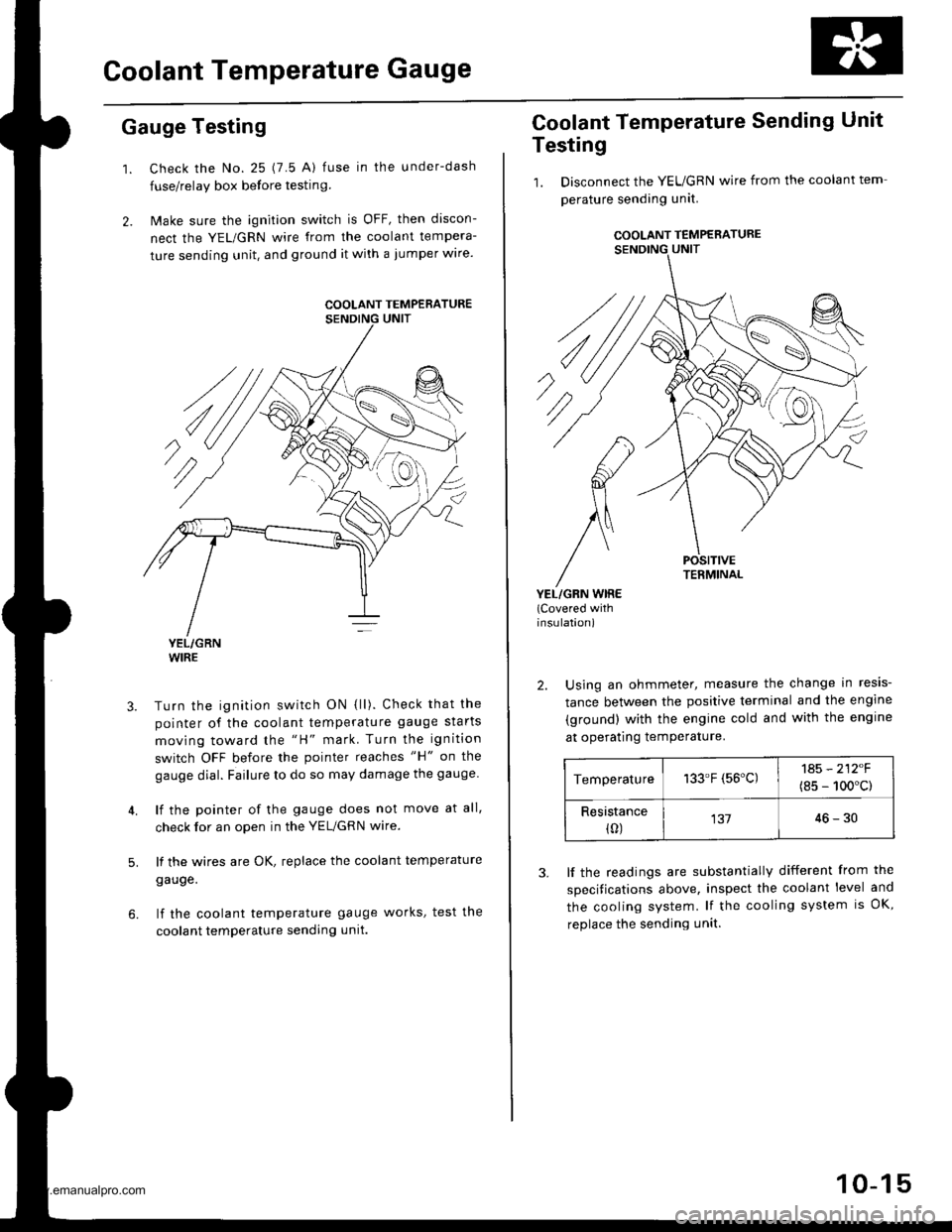
Goolant Temperature Gauge
Gauge Testing
1. Check the No. 25 (7.5 A) fuse in the under-dash
fuse/relay box before testin9.
2. Make sure the ignition switch is OFF, then discon-
nect the YEL/GRN wire from the coolant tempera-
ture sending unit. and ground it with a jumper wire.
YEL/GRNWIRE
Turn the ignition switch ON {ll). Check that the
pointer of the coolant temperature gauge starts
moving toward the "H" mark. Turn the ignition
switch OFF before the pointer reaches "H" on the
gauge dial. Failure to do so may damage the gauge.
lf the pointer of the gauge does not move at all,
check for an open in the YEL/GRN wire.
lf the wires are OK, replace the coolant temperature
gauge.
lf the coolant temperature gauge works, test the
coolant temperature sending unit.
5.
COOLANT TEMPERATURE
Coolant Temperature Sending Unit
Testing
1. Disconnect the YEUGRN wire from the coolant tem
perature sending unit.
COOLANT TEMPERATURE
POSITIVETERMINAL
YEL/GRN WIRE(Covered withinsulation)
2. Using an ohmmeter, measure the change in resis-
tance between the positive terminal and the engine
(ground) with the engine cold and with the engine
at operating temPerature.
Temperature133.F (56'C)1A5 - 212F
(8s - 100'c)
Resistance(0)13746-30
3. lf the readings are substantially different from the
specitications above, inspect the coolant level and
the cooling system. lf the cooling system is OK,
replace the sending unit.
10-15
www.emanualpro.com
Page 283 of 1395

Fuel Cut-off Control
. During deceleration with the throttle valve closed, current to the fuel injectors iscutoffto improvefuel economyat
speeds over 970 rpm ('97 - 98 models), 920 rpm ('99 - 00 modelsl.
. Fuel cut-off action also takes place when engine speed exceeds 6,500 rpm ('97 - 98 models), 6900 rpm ('99 - 00
models), regardless of the position of the throttle valve, to protect the engine from over-rewing.
With Ay'T model. the PCM cuts the fuel at engine speeds over 5,000 rpm when the vehicle is not moving.*'�
4,./C Comoressor Clutch Relav
When the ECM/PCM receives a demand for cooling from the air conditioning system, it delays the compressor from
being energized, and enriches the mixture to assure a smooth transition to the Ay'C mode.
Evaporative Emission (EVAP) Purge Control Solenoid Valve
When the engine coolant temperature is above 154"F (68'C), the ECM/PCM controls the EVAP purge control solenoid
valve which controls vacuum to the EVAP purge control canister,
Alternator Control
The system controls the voltage generated at the alternator in accordance with the electrical load and driving mode.
which reduces the engine load to improve the fuel economy.
PCM Fail-saf e/Back-up Functions
1. Fail-safe Function
When an abnormality occurs in a signal from a sensor, the ECM/PCM ignores that signal and assumes a pre-pre
grammed value for that sensor that allows the engine to continue to run.
2. Back-up Function
When an abnormality occurs in the ECM/PCM itself, the fuel injectors are controlled by a back-up circuit independent
of the system in order to permit minimal driving.
3. Self-diagnosis Function IMalfunction Indicator Lamp (MlL)l
When an abnormality occurs in a signal from a sensor, the ECM/PCM supplies ground for the MIL and stores the DTC
in erasable memory. When the ignition is initially turned on {ll), the ECM/PCM supplies ground for the MIL for two
seconds to check the MIL bulb condition.
4. Two Trio Detection Method
To prevent false indications, the Two Trip Detection Method is used for the HO2S*1, fuel metering-related. idle control
system, ECT sensor and EVAP control system self-diagnostic functions. When an abnormality occurs, the ECM/PCM
stores it in its memory. When the same abnormality recurs after the ignition switch is turned OFF and ON (ll) again,
the ECM/PCM informs the driver by lighting the MlL. However, to ease troubleshooting, this function is cancelled
when you jump the service check connector, The MIL will then blink immediately when an abnormality occurs.
5. Two (or Three) Driving Cycle Detection Method {'97 model)
A "Driving Cycle" consists of starting the engine, beginning closed loop operation, and stopping the engine. lf misfir-
ing that increases emissions or EVAP control system malfunction is detected during two consecutive driving cycles.
or TWC deterioration is detected during three consecutive driving cycles, the ECM/PCM turns the MIL on. However, to
ease troubleshooting, this function is cancelled when you jump the service check connector. The MIL will then blink
immediately when an abnormality occurs.
*1: '97 - 98 models*2: '99 - 00 models
5.
www.emanualpro.com
Page 294 of 1395
![HONDA CR-V 1997 RD1-RD3 / 1.G Workshop Manual
PGM-FI System
Manifold Absolute Pressure (MAP) Sensor (contd)
[tn,t nn-] The scan tool indicates Diagnostic Trouble Code (DTC) P0108: A high voltage (low vacuum) problem in the|jg Manifold Absolute HONDA CR-V 1997 RD1-RD3 / 1.G Workshop Manual
PGM-FI System
Manifold Absolute Pressure (MAP) Sensor (contd)
[tn,t nn-] The scan tool indicates Diagnostic Trouble Code (DTC) P0108: A high voltage (low vacuum) problem in the|jg Manifold Absolute](/img/13/5778/w960_5778-293.png)
PGM-FI System
Manifold Absolute Pressure (MAP) Sensor (cont'd)
[tn,t nn-] The scan tool indicates Diagnostic Trouble Code (DTC) P0108: A high voltage (low vacuum) problem in the|jg Manifold Absolute Pressure (MAP) sensor.
MAP SENSOR 3P CONNECTOR IC131I
Wire side of female terminals
vcclIYEL/RED}
PCM CONNECTOR D I16PI
JUMPER WIRE
sGlIGRN/WHTI
Wire side of lemale termin6ls
1
(To page 11,93)': '98 - 00 models
1-92
tcRN/wHrll IIRED/GRN|
The MIL has boen reported on.DTC m108 is slored.
Problem veritication:1. Start the engine. Hold theengine at 3,000 rpm with noload (in Park or neutral) untilthe radiator fan comes on, thenlet it idle.2. Check the MAP with the scantool.
Intermittent tailuro, system i3 OKat this time. Check tor ooor con-nections or loose wires at C131IMAP s6nsor) snd the ECM/rcM.
ls 101 kPa {760 mmHg,30 in.Hg),2.9 V or higher indicated?
Check Ior an open in the MAPsensor:1. Turn the ignition switch OFF.2. Disconnect the MAP sensor3P connector.3. lnstall a jumper wire betweenthe MAP sensor 3P connectorterminals No.3 and No.2.4. Turn the ignition switch ON {ll).5. Check the MAP with the scantool.
ls 10'l kPa (760 mmHg,30 in.Hg),2.9 V or higher indicated?
Check for an open in wire (SGlliDel:1. Remove the jumper wire.2. Measure voltage between theMAP sensor 3P connector ter-minals No. 1 and No- 2.
R6p.ir open in the wire betwoenthe ECM/PCM (D12, CTrl and theMAP sensor.
ls there approx. 5 V?
Check for an open in the wire(MAP line):1. Turn the ignition switch OFF.2. lnstall a iumper wire on thePCM connectors between D3and D12.3. Turn the ignition switch ON (ll).4. Check the MAP wirh the scantool.
Ropair opon in the wire betweenthe PCM {D3, .nd the MAP son-3('t.
ls 101 kPa 1760 mmHg, 30 in.Hg),2.9 V or higher indicated?
YES
www.emanualpro.com
Page 315 of 1395
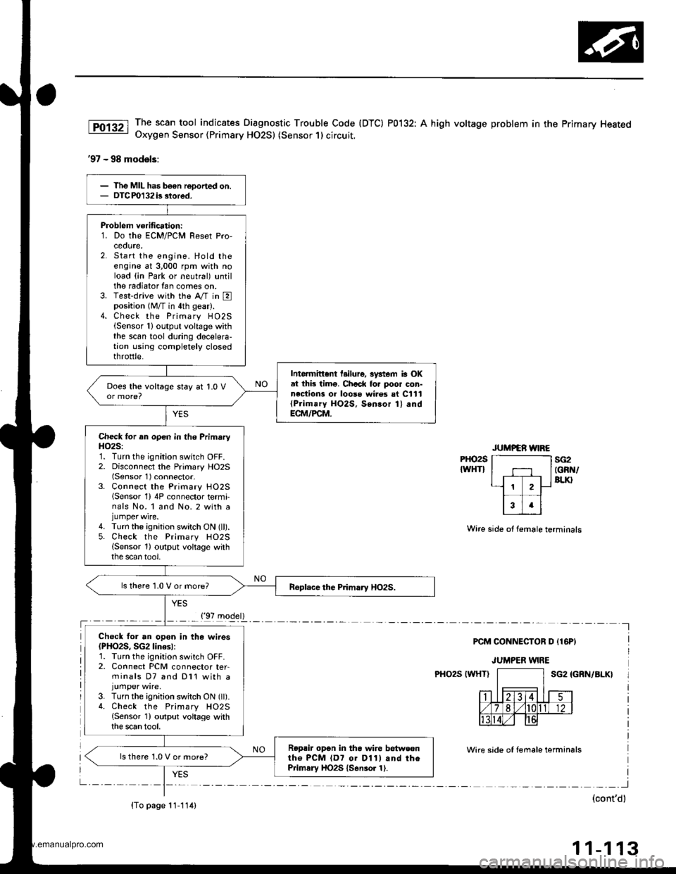
The scan tool indicates Diagnostic Trouble Code (DTC) P0132: A high voltage problem in the Primary HeatedOxygen Sensor {Primary HO2S) (Sensor 1) circuit.
'97 - 98 models:
PHO2S
IWHTIsG2IGRN/BLK}
Wire side ot female terminals
PCM CONNECTOR D {16PI
JUMPER WIRE
PHO2S IWHTISG2 IGRN/BLK}
Wire side of temale terminals
I
(cont'dl
11-113
Problem verification:1. Do the ECM/PCM Resot Pro,ceoute,2. Start the engine. Hold theengine at 3,000 rpm with noload (in Park or neutral) untilthe radiator fan comes on.3. Test-drive with the Ay'T in Eposition (M/T in 4th gear).4. Check the Primary H02S{Sensor 1}output voltage withthe scan tool during decelera-tion using completely closedthrottle.
Intormittent l.ilure, 3ystem ia OKat thb timo. Chcck fo. poor con-nections 01 looso wi.es at C111{Prim!ry HO2S, Sensor 1} andECM/PCM.
Does the voltage stay at 1.0 V
Check for an open in th6 PrimaryH()2S:1. Turn the ignition switch OFF.2. Disconnect the Primary HO2S(Sensor 1) connector-3. Connect the Primary HO25lSensor 1) 4P connector termi-nals No. 1 and No. 2 with ajumper wire.4. Turn the ignition switch ON (ll).5. Check the Primary HO2S(Sensor 1) output voltage withthe scan tool,
ls there 1.0 V or more?
Ch€ck for an opon in the wires(PHO2S, SG2linesl:1. Turn the ignition switch OFF.2. Connect PCM connector ter-minals D7 and Dl1 with a
3. Turn the ignition switch ON (ll).4. Check the Primary HO2S{Sensor 1) output voltage withthe scan tool.
Roprir opon in the wire betweontho PCM {D7 01 D11l and thePrimsry HO2S {S6nsor 1).
ls there 1.0 V or more?
{'97 model}
{To page 11-114)
www.emanualpro.com
Page 317 of 1395
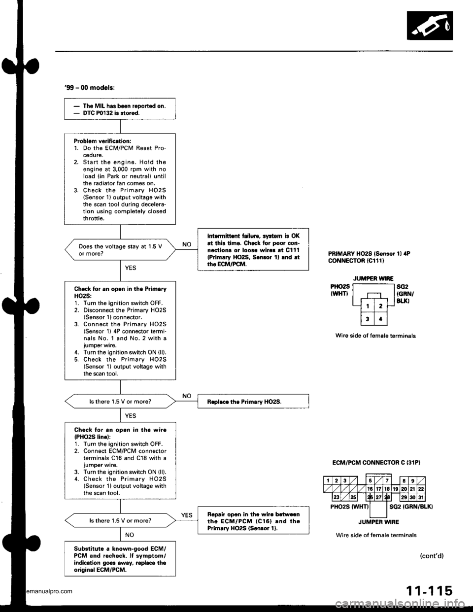
'99 - 00 modols:
Th6 Mll has b€on reDortod on.DTC ml32 is itorod.
Problem vorification:'1. Do the ECi!4/PCM Reset Procedure,Start the ongine. Hold theengine at 3,000 rpm with noload (in Park or neutral) untilthe radiator fan comes on.Check the Primary HO2SlSensor 1) output voltage withthe scan tool during decelela-tion using completely closedthroftle.
Int.rmitt .fi tailuro, syltom b OKat thit tima. Check for poor con-nactiona oi loo3a wirar !t Cltl(Primrry HO2S, S.nror 1) .nd .tth. ECM/FCM.
Doos the voitage stay at 1.5 Vor more?
Check for an opsn in the PrlmaryHO2S:1. Turn the ignition switch OFF.2. Disconnect the Primary HO2S(Sensor 1)connector.3. Connect the Primary HO2S(Sensor 1) 4P connector t6rmi-nals No. 1 and No. 2 with a
iumperwire.4. Turn the ignition switch ON (ll).
5, Check the Primsry H02S(Sensor 1) output voltage withthe scan tool,
lsthere 1.5 V or more?
Check for an op6n in th6 wiro{PHO2S line):1. Turn tho ignition switch OFF.2. Connect ECM/PCM connectorterminals C16 and C18 with a
iumper wire.3. Turn the ignition switch ON lll).4. Check the Primary HO2S(Sensor 1) output voltage withthe scan tool.
Ropair opon in thc wire bc{w.cnthe ECM/PCM {Cl6}.nd thePrimary HO2S {S€nror 1}.ls there 1.5 V or more?
Substituto a known-good ECM/PCM snd rochock. lf 3ymptom/indicetion go€a awry, roplaca thoorigin.l ECM/PCM.
PRIMARY HOzS (S6n!or 1l aPCoNNECTOR lcltl)
Pt()2sIWHTIsG2{GRN/BTJ(I
Wire side of tem6le terminsls
ECM/PCM CONNECTOR C (31P}
IGRN/BLKI
JUMPER WIRE
Wire side ol temale t6rmin6ls
(cont'd)
-1 15
2789
/1617't819120A22
23E29g)31
PHO2S {WHTIsG2
11
www.emanualpro.com
Page 320 of 1395
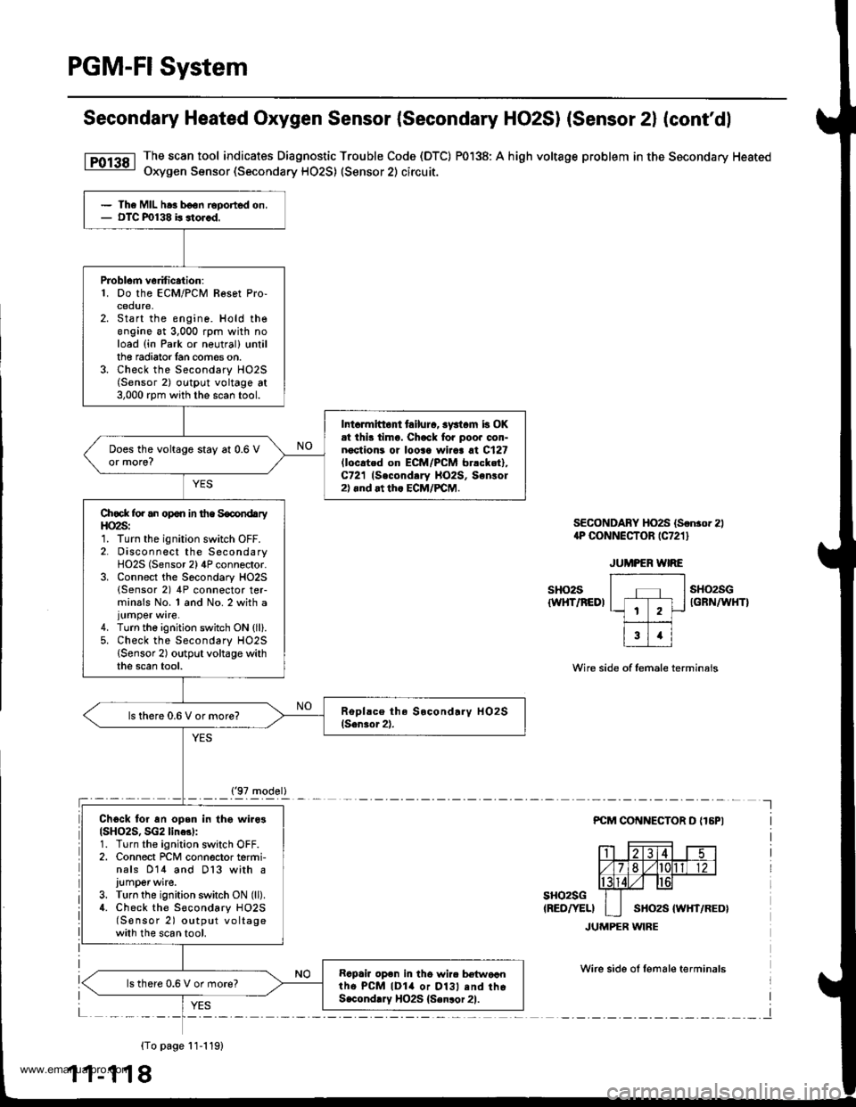
PGM-FI System
Secondary Heated Oxygen Sensor (Secondary HO2SI (Sensor 2l (cont'dl
The scan tool indicates Diagnostic Trouble Code (DTC) P0138: A high voltage problem in the Secondary Heated
Oxygen Sensor (Secondary HO2S) (Sensor 2) circuit.
SECONDABY HO2S (Sonror 2)1P CONNECTOR rC721 l
sHo2s{WHT/REDI
sH()2sGIGFN/WHTI
Wire side of female terminals
PCM COI{NECTOR D {16PI
sHo2sG(RED/YELI
JUMPER WIRE
Wirc side ol lemale terminals
{To page 11-119)
1 1-1 18
The MIL hra b€on Eported on,OTC m138 b stor.d.
PJoblcm v6dtic.tion:1. Do the ECM/PCM Resot Pro-cedure,Start the engine. Hold theengine at 3,000 rpm with noload (in Park or neutral) trntilthe radiator lan comes on.Check the Secondary HO2S(Sensor 2) outpl.rt voltage at3,000 rpm with the scan tool.
Int.rmitto tailurc, syst.m b OKrt ihi! timo. Chack fo. poo. oon-noctioni or looaa wiiaa at C127lloc.ted on EcM/PcM br.cket),C721 (Second!ry llO2S, Sonlol2).nd at th. ECM/PCM.
Does the voltage stay at 0.6 Vor more?
Chock for an opon in the SocondaryHO2S:1. Turn the ignition switch OFF.2. Disconnect the SecondaryHO2S (Sensor 2) 4P connector.3. Connect the Socondary HO2S(Sensor 2) 4P connector ter-minals No. 1 and No. 2 with a
4. Turn the ignition switch ON {ll}.5. Check the Secondary HO2S{Sensor 2) output voltage withthe scan tool.
ls there 0.6 V or more?
Ch6ck for an open in thg wiro3(SH()2S, SG2 line3l:1. Turn the ignition switch OFF.2. Connect rcM connector termi-nals 014 and D13 with a
J!mper wite.3. Turn the ignition switch ON (ll).
4. Check the S€condary HO2S(S€nsor 2) output voltagewith the scan tool.
Rapair op6n in tho wir. b€{woantho PcM lDla or Dl3l .nd thoS.condlry HO2S {Senlor 21.
lsthere 0.6 V or more?
('97 model)
www.emanualpro.com
Page 356 of 1395
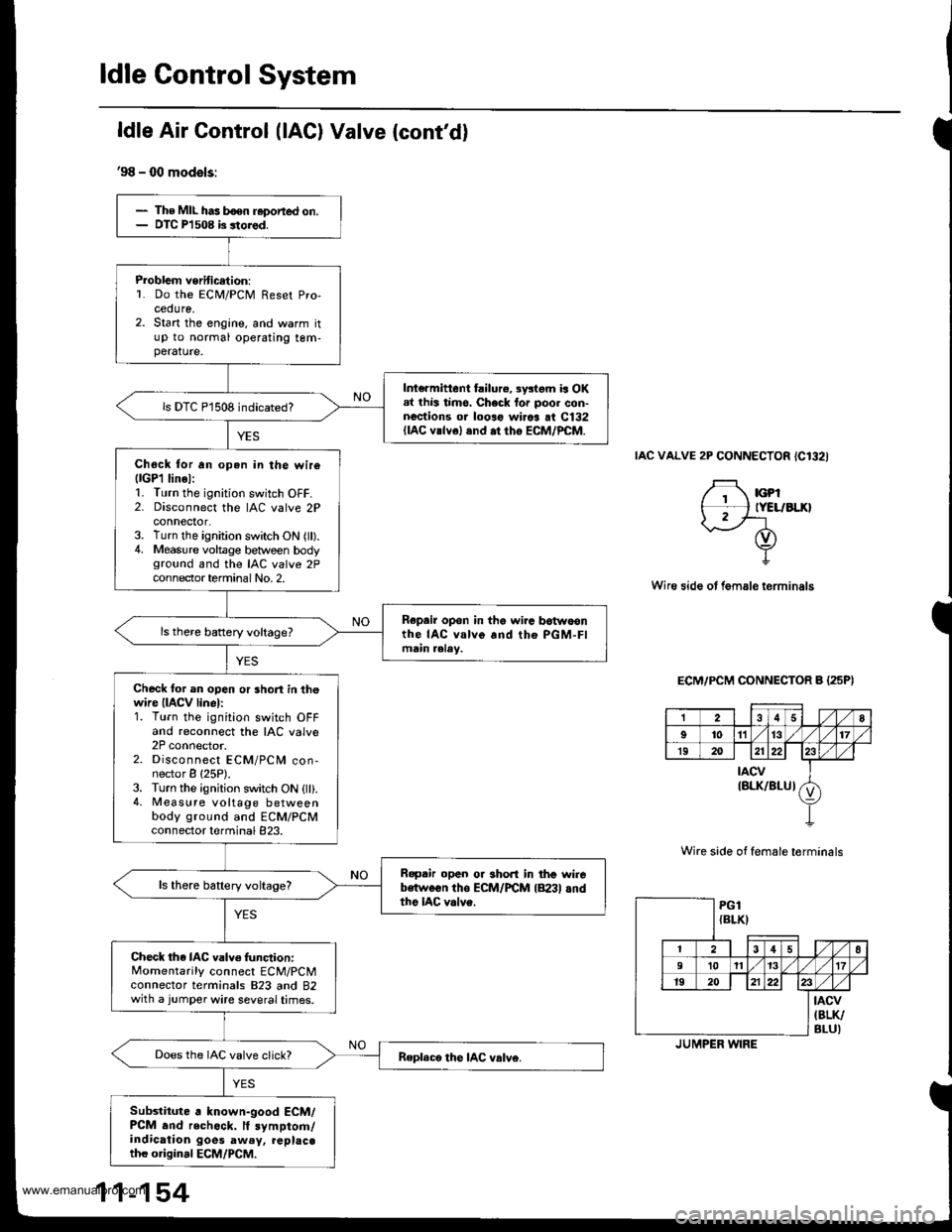
The MIL has boen r.ported on.DIC Pl 508 b 3tored.
Problem veritication:L Do the ECM/PCM Reset Pro-cedure.2. Start the engine, and warm itup to normal operating tem-perature.
Int€rmittent failure, systom is OKal lhis timo. Check lor poor con-nections or looro wirca at C132(lAc vrlvel and .t rho EcM/PcM.
ls DTC P1508 indicated?
Chock tor an open in the wir6llGPl linel:1. Turn the ignition switch OFF.2. Disconnect the IAC valve 2Pconnector,3. Turn the ignition switch ON (ll).4. Measure voltage between bodyground and the IAC valve 2Pcon nector termina I No, 2.
Repair opon in the wira botwoonthe IAC valve and tho PGM-FImain aalay.
Check tor an open or short in thewire (IACV linel:1. Turn the ignition switch OFFand reconnect the IAC valve2P connector.2. Disconnect ECM/PCM con-nector B {25P).3. Turn the ignition switch ON {ll}.4. Measure voltage betweenbody ground and ECM/PCMconnector terminal 823.
Ropair open or short in thg wirebetween tho ECM/FCM lB23l andthe IAC valve.
ls there battery voltage?
Check the IAC valve func,tion:Momentarily connect ECM/PCMconnector terminals 823 and 82with a jumper wire several times.
Does the IAC valve click?
Subslitute . known-good ECM/PCM .nd rechock. lf symptom/indication goes aw.y, replac.th€ original ECM/PCM.
ldle Air Control (lAC) Valve {cont'd}
'98 - 00 models:
IAC VALVE 2P CONNECTOR {C132I
F rcpt*l tYELrBLxlI2/'-- rf)
Y
Wire side ot fem.le terminals
ECM/PCM CONNECTOR B (25PI
Wire side of female torminals
258
9'to1l13t7
1920212223
tAcv(BLK/BLUIv
PG1{BLKI
12 | t3 4 58
910 111317
1920 | 121)22
tAcv(BLK/
BLU)JUMPER WIRE
www.emanualpro.com
Page 358 of 1395
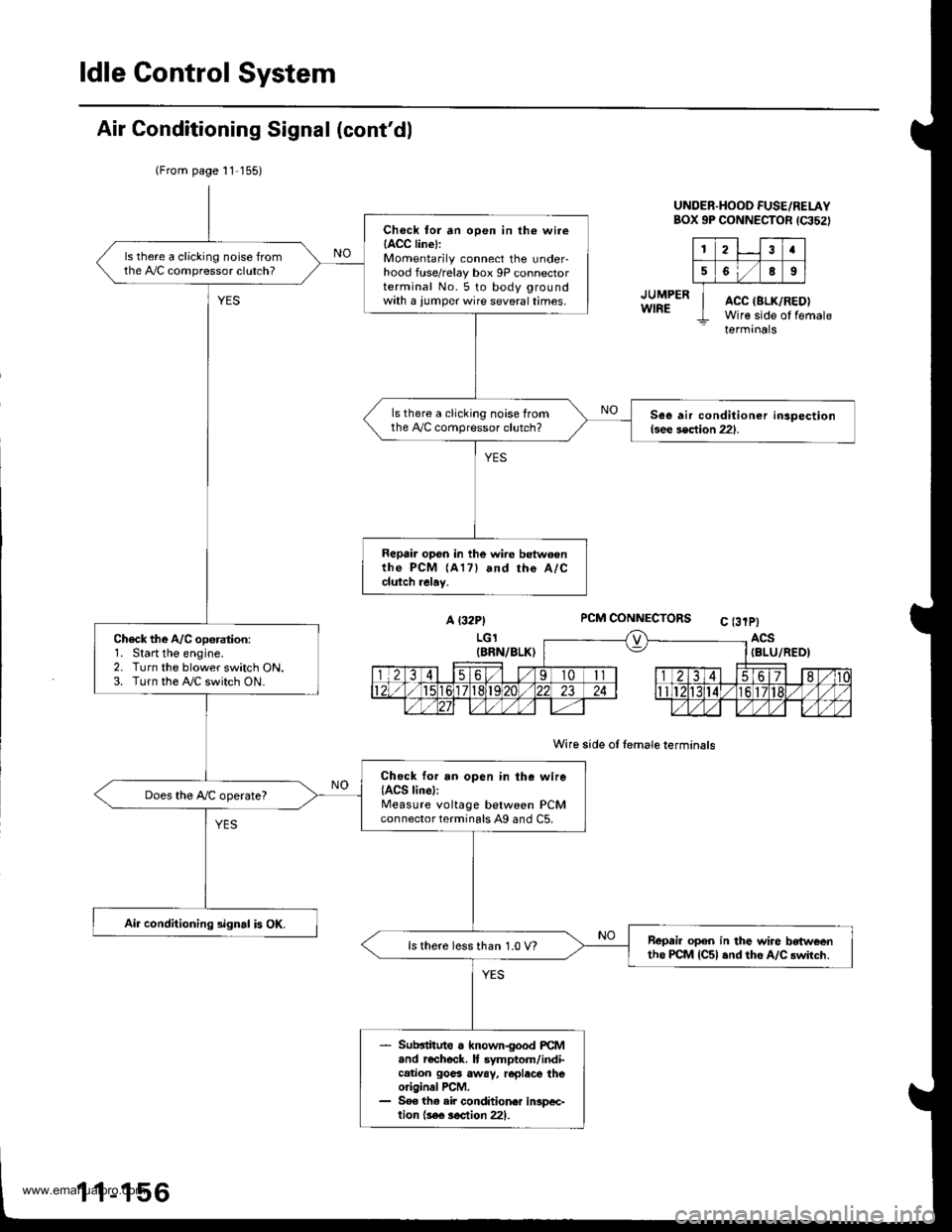
ldle Gontrol System
Air Conditioning Signal (cont'dl
(From page 11-'155)
JUMPERWIRE
UNOER.HOOD FUSE/RELAYBOX 9P CONNECTOR tqt52)
123I
56I
ACC IBLK/RWire side ofACC IBLK/REDIWire side of femaletermrnats
A t32PlPCM CONNECTORS C t3rp)
Wire side ol lemale terminals
Ch6ck for an open in th€ wire(ACC linel:Momentarily connect the under-hood fuse/relay box 9P connectorterminal No.5 to body groundwith a jumper wire several times.
ls there a cl;cking noise fromthe 4!/C compressor clutch?
ls there a clicking noise fromthe 4!/C compressor clutch?See air condiiioner inspection{see section 221.
Repai. op6n in the wire betwoenthe PcM (A17) and tho A/Cclutch relay.
Check the A/C operation:1. Start the engine.2. Turn the blower switch ON.3. Turn the A"/C switch ON.
Check for an open in the wire(ACS line):Measure voltage between PCMconnector terminals Ag and C5.
Does the A,/C operate?
Air conditioning signal is OK.
Repair open in the wire betweenthe PCM lCSl and the A/C awitch.ls there less than 1.0 V?
- Subqtitute a known-good FCM.nd r€ch6ck. lt 3ymptom/indi-cation goes awav, replece theoriginal rcM.- Soe th€ eir conditioner in3pec-tion (s6€ aec.tion 22).
www.emanualpro.com
Page 361 of 1395
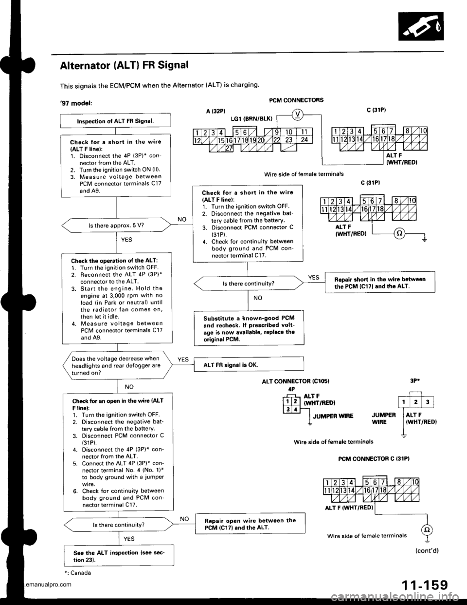
Alternator (ALT) FR Signal
This signals the ECM/PCM when the Alternator (ALTI is charging.
,97 modet: PCM GONNECTORS
wire side of female terminals
ALT CONNECTOR (C1O5I
lPr-F- ALT F
lll2llw|{frREDl|3.r-'l-
lruueen wne
c (31P|
wire side ol f€male terminals
PCM CONNECTOR C I31P)
3Pr
JUMPERWIRE
Inspection ot ALT FR Signal.
Check lor a short in the wire
{ALT F line}:1. Disconnect the 4P 13Pi* connector from the ALT.2. Turn the ignition switch ON (ll)
3, Measure voltage betweenPCM connector terminals C17
and A9.Check for a short in the wire(ALT F linel:1. Turn the ignition switch OFF.2. Disconnect the negative bat'tery cable from the battery.3. Disconnect PCM connector C(31P).
4. Check for continuity betweenbody ground and PCM connector terminal C17.
ls there approx. 5 V?
Check th€ ope.ation of the ALT:
1. Turn the ignition switch OFF2. Reconnect the ALT 4P {3Pi*connector to the ALT.3. Start the engine. Hold theengine at 3,000 rpm with no
load (in Park or neutral) untilthe radiator fan comes on,
then let it idle.4. Measure voltage betweenPCM connector terminals C17and A9.
Ropeir short in the wir6 betweonthe PCM lC17l and the ALT.
Substitut. a known-good PCM
and recheck. lf prescribed volt-
age is now availablo, replace the
originalPCM.
Does the voltage decrease when
headlights and rear defogger are
turned on?ALT FR signal b OK.
Ch€d( for an op€n in tho wire IALTF linel:1. Turn the ignition switch OFF.2. Disconnect the negative bat-tery cable lrom the battery.3. Disconnect PCM connector C(31P).
4. Disconnect the 4P (3P)* con-nector lrom the ALT.5. Connect the ALT 4P (3P)* con-nector terminal No. 4 (No. 1)*to body ground with a iumper
6. Check for continuity betweenbody ground and PCN4 con'nector terminal Cl7.
Repair open wi.e between thePCM lCl7l and the ALT.ls there continuity?
ALT F IWHT/REDI
Wire side of female terminals
1 1-159
www.emanualpro.com