pgm-fi relay HONDA CR-V 1997 RD1-RD3 / 1.G Workshop Manual
[x] Cancel search | Manufacturer: HONDA, Model Year: 1997, Model line: CR-V, Model: HONDA CR-V 1997 RD1-RD3 / 1.GPages: 1395, PDF Size: 35.62 MB
Page 204 of 1395

Fuel and Emissions
Special Tools ...................... 11-2
Component Locations
lndex ...................... ....,.... 11-3
Svstem Description
Vacuum Connections ...........,....,.,................. 1 1-9
Electrical Connections ................................... 1 1-15
System Connectors .,.,,.,............................,.,. 1 1-36
Troubleshooting
Troubleshooting Procedures,.,..................... 11-60
Engine Control Module/Powertrain ConttolModule Terminal Arrangement .............., 11-67
Diagnostic Trouble Code Chart .................... 1 t-75
How to Read Flowcharts .......,.....,.,............... I 1-79
PGM-Fl System
System Description .................,.,.,,,............... 1 1-80
Troubleshooting Flowcharts
Engine Control Module/PowertrainControl Module ........11-52
Manifold Absolute Pressure Sensor ............. 11-90
Intake Air Temperature Sensor .................... 1 1-95
Engine Coolant Temperature Sensor .,..,.,.... 1 1-99
Throttle Position Sensor ...........,.....,.,.,..,...... I 1'103
Primary Heated Orygen Sensor (Sensor 1) ... 11-110
Secondary Heated Oxygen Sensor{Sensor 2l .................. 1 1-117
Heated Oxygen Sensor Heater ..................... 11-121
Fuef Supply System ......11-124
Random Misfire ,....,.,..... 11-126
Mistire Detected in One Cylinder .....-........... 11-128
Knock Sensor ................ 11-130
CKP/TDC/CYP Sensor .................................... 1 1-131
Vehicle Speed Sensor ...............................,.... 1 1-135
Barometric Pressure Sensor .....,...,...,.,,........ 1 1-137
Electrical Load Detector ...,.,.......................... 1 1-138
CKF Sensor ................,.,, '11-112
ECM/PCM lnternaf Circuit ............................. 11'117
HO2S Replacement .,.,.,. 11-148
ldle Control System
System Description ............ 11-149
Troubleshooting Flowcharts
ldle Control System ...... 11-150
fdle Air Control Valve ......................,............. 11-152
Air Conditioning Signal ................................. I 1-155
Alternator FR Signal ...................................... 1 1-159
Starter Switch Si9na1 .................................... t l-161
Power Steering Pressure Switch Signal ...... 11-162
Brake Switch Si9na1 ...................................... 11-166
Fast ldle Thermo Valve .,.,.............................,.,.,. 11-168
ldle speed setting .............. 11-169
Fuel Supply System
Fuel Lines ............................ 11-171
Fuef Tube/Ouick-Conneci Fittings ..................... 11 -175
System Description ............ 11-178
Fuel Pressurg ...................... 11-178
Fuel Iniectors ................,..... 11-179
Fuel Pressure Re9u1ator .............................,.,...., f 1-181
Fuef Fifter ....,.,.,.,,,,.,............11-142
Fuel Pump ........................... 11-183
Fuel Gauge .......................... 11-184
Fuel Gauge Sending Unit ................................... I 1-185
Low Fuel Indicator System ...........,.,..,............... 1 1-185
PGM-FI Main Relay ............. 11-187
Fue|Tank................ ............. 11-191
Intake Air System
System Description ............ 11-193
Air Cleanel ,.,.,..................... 11-194
Throttle Cable ..................... 11-194
Throttle Body........ .............. 11-196
Emission Control System
System D$cription ...,....,.,. 11-199
Tailpipe Emission ............... 11-199
Three Way Catalytic Converter ..................,.,...,, 11-199
Positive Crankcase Ventilation System .,.,,,,.,.., 11-2O1
Evaporative Emission Controls .........,.,.,............ 11-203
www.emanualpro.com
Page 208 of 1395
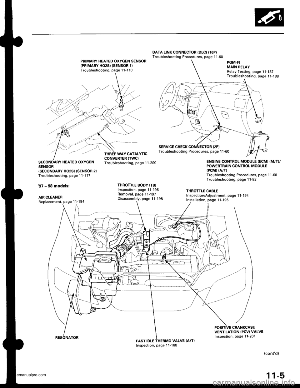
DATA LINK CONNECTOR {DLC) I16P}Troubleshooting Procedures, page 1 1'60PRIMARY HEATED OXYGEN SENSOR
{PRIMARY HO2SI {SENSOR 1)Troubleshooling, page 11 110
SECONDARY HEATED OXYGENSENSOR{SECONDARY HO2S) {SENSOR 2)Troubleshooting, page 1 1-1 17
'97 - 98 models:
AIR CLEANERReplacement, page 1 1'194
Troubleshooting, page 1 'l -200
THROTTLE BODY (TB)Inspection, page 11 196Removal, page 11-197Disassembly, page 1 1-'198
POWERTRAIN CONTROL MODULE(PCM) (A/TI
Troubleshooting Procedures, page 1 1-60Troubleshooting. page 1 1'82
THROTTLE CABLEInspection/Adjustment, page 1 1-1 94Installation, page 11- 195
VENTILATION (PCV) VALVEInspection, page 1 1-201FAST IDLEVALVE (A/T}
(cont'd)
1 1-5
PGM-FIMAIN RELAYRelay Testing, page 11-l87Troubleshooting. page 1'1 188
SERVICE CHECK CONNECTOR {2PITroubleshooting Procedures, page 1 1-60
,a'=_-_
WAY CATALYTIC
Inspection, page 1 1-168
www.emanualpro.com
Page 282 of 1395

PGM-FI System
System Description
INPUTS
CKP/TDC/CYP Sensor
CKF Sensor
MAP Sensor
ECT Sensor
IAT Sensor
TP Sensor
Primary HO2S
Secondary H02S
vss
KS*5
BARO Sensor
ELD*6
Starter Signal
ALT FR Signal
Air Conditioning Signal
Ay'T Gear Position Signal*1
Baftery Voltage (lGN.1)
Brake Switch Signal
PSP Switch Signal
Fuel Tank Pressuae Sensor*4. *5
Countershaft Speed Sensor*1
Mainshaft Speed Sensor*r
OVER-DRIVE Switch Signal*s
ENGINE CONTROL MODULE (ECM)/
POWERTRAIN CONTROL MODULE (PCM) OUTPUTS
|iuel 1"j""- Th,rhg ""d Drrafr";-l
Et*-.nt"tdt"cont.orl
to,r*,c;;trffi;]
l.----.---:. .Lrgnrnon |lmrng Lonrror I
Ecir/PcM B*k',p Fr""il]
m;"t-ll-r*'io*l
Fuel Injectors
PGM-Fl Main Relay (Fuel Pump)
MIL
IAC Valve
Ay'C Compressor Clutch Relay
Radiator Fan Relay
Condenser Fan Relay
ALT
tcM
EVAP Purge Control Solenoid
Valve
Primary HO2S Heater
Secondary H02S HeaterEVAP Bypass Solenoid Valve*a *5
EVAP Control Canister Vent Shut
DLC
Lock-up Control Solenoid Valve*l
Shift Control Solenoid Valve*1
Ay'T Clutch Pressure Control
Solenoid Valve*1
D4 Indicator Light'1 *3, *a
D Indicator Light,l *5
OVER-DRIVE OFF Indicator
Lighl*t *:
*1: A/T {3:'97 model'2: M/f +4:'98 model*5: '99 - 00 models"6: USA
PGM-Fl System
The PGM-Fl system on this model is a sequential multiport fuel injection system.
Fuel iniecior Timing and Duration
The ECM/PCM contains memories for the basic discharge durations at various engine speeds and manifold pressure. The
basic discharge duration, after being read out from the memory, is further modified by signals sent from various sensors
to obtain the final discharge duration.
ldle Air Control
ldle Air Control Valve (lAC Valve)
When the engine is cold, the Ay'C compressor is on, the transmission is in gear, the brake pedal is depressed, the P/S load
is high, or the alternator is charging, the ECM/PCM controls current to the IAC Valve to maintain the correct idle speed.
lgnition Timing Control
o The ECM/PCM contains memories for basic ionition timing at various engine speeds and manifold air flow rates.
lgnition timing is also adjusted for engine coolant temperature.
. A knock control system was adopted which sets the ideal ig nition timing for the octane rating of the gasoline used.*s
Other Control Funstions
1. Starting Control
When the engine is started. the ECM/PCM provides a rich mixture by increasing fuel injector duration.
2. Fuel Pump Control
. When the ignition switch is initially turned on (ll). the ECMiPCM suppli€s ground to the PGM-FI main relay that
supplies current to the fuel pump for two seconds to pressurize the fuel system.
. When the engine is running, the ECM/PCM supplies ground to the PGM-FI main relay that supplies current to the
fuel oumo.
. When the engine is not running and the ignition is on, the ECM/PCM cuts ground to the PGM-FI main relay which
cuts current to the fuel pump.
1 1-80
www.emanualpro.com
Page 284 of 1395
PGM-FI System
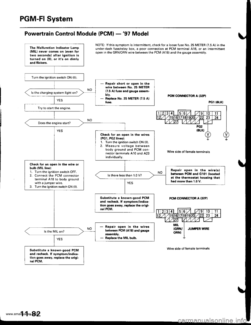
Powertrain Control Module {PCM} -'97 Model
NOTE: lf this symptom is intermiftent, check for a loose fuse No. 25 METER (7.5 A) in theunderdash f{rse/relay box, a poor connection at PCM terminal A18, or an intermittentopen in the GRN/ORN wire between the PCM (A18) and the gauge assembly.
PCM OON ECTOR A {32P}
Wire side of female terminals
PCM CONNECTOR A {32PI
Wire side ot temale terminals
11-42
The Malfunction lndicator LamD(MlL) nev6r comes on {even lortwo seconds) after ignition isturned on (lll, or it's on dimlyand flickers.
Turn the ignition switch ON {ll}.
- Rep.ir short or opon in thowire batween No. 25 METER(7.5 Alfuso and gauge a$€m-bty.- R6pl.c€ No. 25 METER 17.5 Alfus€.
ls the charging system light on?
Try to stan the engine.
Does the engine start?
Chock tor.n open in th6 wire3{PG1, PG2linesl:1. Turn the ignition switch ON (ll).2. Measure voltage betweenbody ground and PCM con-nector terminals A10 and A23individually.
Check for an op€n in the wir6 orbulb (MlL lin€l:1. Turn the ignition switch OFF.2. Connect the PCM connectorterminal A18 to body groundwith a iumper wire.3. Turn the ignition switch ON {ll).
n€peir open in tho wirelslhwoon PCM and Glol (loc!t.d
at thc tha.mo3tat houling thrthtd moro th.n 1.0 V.
ls thore l€ss than 1.0 V?
Substituto . known-good PCMand r€check. ll symptom/indica-tion goss away, rcplaca the origi-nal PCM.
- R6pai. open in th. wileibelwoon rcM lAl8l dnd g.ugea3rombly.- Roolac€ the MIL bulb.
ls the MIL on?
Substitut6 a known-good PCMand rocheck. ll 3ymptom/indica-tion goes away, replace the o.igi-n.l PCM.
PGl IBLKI
www.emanualpro.com
Page 286 of 1395
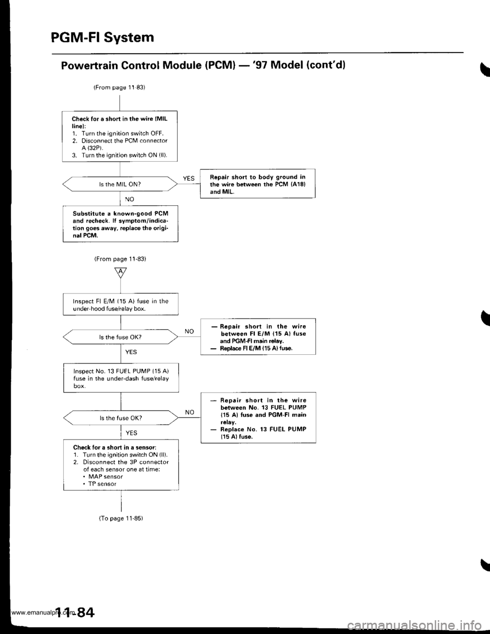
Powertrain Control Module (PCM) -'97 Model (cont'dl
(From page 11 83)
Check for a short in the wire (MlL
line):1. Turn the ignition switch OFF.2. Disconnect the PCM connectorA {32P).3. Turn the ignition switch ON (ll).
Repair short to body ground inthe wire between the PCM {418}and MlL.ls the MIL ON?
Substitute a known-good PCMand recheck. lf symptom/indica-tion goes away. replace the origi-nal PCM.
Inspect Fl E/M (15 A) fuse in theundeFhood fuse/relay box.
- Reoair shod in the wirebetween Fl E/M {15 A} fuseand PGM-FI main relav.- Replace FIE/M 115 A)fuse.
Inspect No. 13 FUEL PUMP (15 Aifuse in the underdash fuse/relay
- Repair short in lh€ wirebolween No. 13 FUEL PUMP
115 A) Iuse and PGM-FI main
- Replace No. 13 FUEL PUMP
115 A) fuse.
Check loJ a short in a sensor:1. Turn the ignit;on switch ON (ll).
2. Disconnect the 3P connectorof each sensor one at time:. MAP sensor
(To page 11-85)
11-84
www.emanualpro.com
Page 287 of 1395
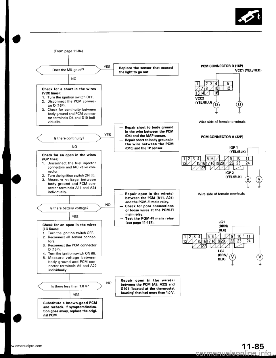
(From page 11-84)
Reolace the Sensor that causedthe lighl lo go out.Does the MIL go off.,
Check for a short in the wires
lvCC linesl:1. Turn the ignition switch oFF.2. Disconnect the PCM connector D (16P).
3. Check for continuity betweenbody ground and PCM connector terminals D4 and Dl0 individually.
Repair shorl lo body ground
in the wile between the PCM
{D4} and the MAP sensor.Repair short to body ground inth€ wire between the PCMlol0l and the TP sensor.
Check tor an open in the wires
llGP line3l:1. Disconnect the fuel injectorconnectors and IAC valve con
2. Turn the ignition switch ON (lli.
3. [,4easure voltage betweenbody ground and PCM con'nector terminals A'11 and A24individually.- Repair open in the wire(slboiween the PCM 1A11, A24)and the PGM-Fl main relav.- Ch€ck lor poor connectionsor loose wires at ihe PGM-FImain relay.- Tesi lhe PGM-FI main relav
{see p.g6 1l-1871.Check for an open in the wires
{LG linesl:1. Turn the ignition switch OFF.2, Reconnect all sensor connec-tors,3. Reconnect the PCM connectorD (16P).
4. Turn the ignition switch ON (ll).
5, M easu re voltage betweenbody ground and PCM connector terminals Ag a^d 422individually.
R6pair open in the wire{slbetween the PCM {A9. A22l andG101 {located at the thetmostathousing) that had more than 1.0 V.
ls there less than 1.0 V?
Substituto a known-good PCMand rech€ck. It symptom/indica-tion goos away, replace the origi-nal PCM.
PCM CONNECTOR D (16PI
VCCl NEL/RED}
Wire side of female terminals
PCM CONNECTOR A (32PI
Wire side of lemale terminals
1 1-85
www.emanualpro.com
Page 288 of 1395
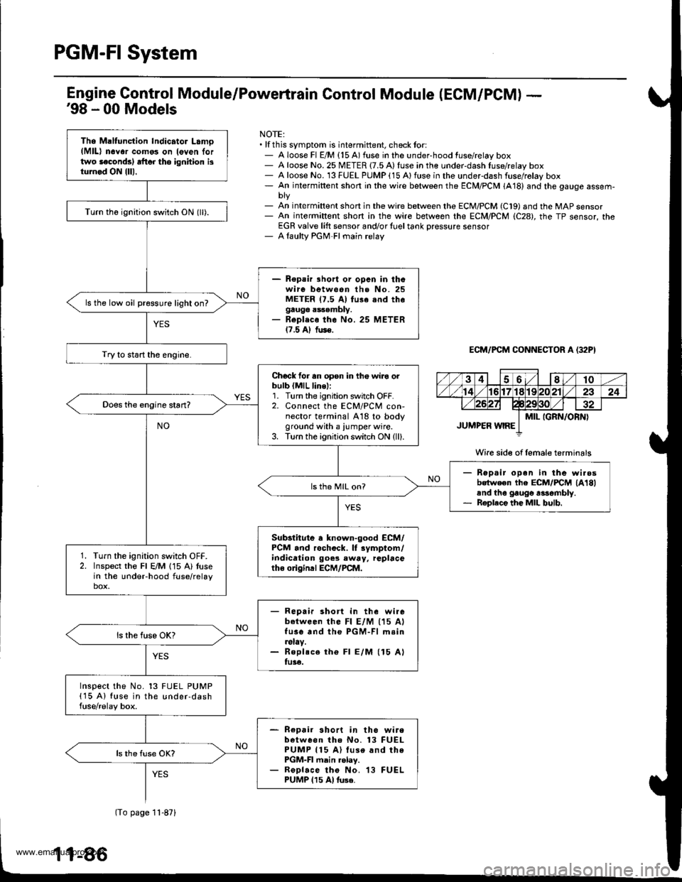
PGM-FI System
Tho Maltunction Indicator Lamo(MlL) n6Yor como3 on leven lortwo laconds) rft6r tho ignhion isturnod ON {lll.
Turn th6 ignition switch ON (ll).
- Repair lhort or opcn in thowire between the No. 25METER 17.5 Al fu3e snd thegauge assembly.- Repl.co the No. 25 METER17.5 Al fus€.
ls the low oil pressure light on?
Try to start the engine.
Chock for an opsn in th€ wiro orbulb {MlL line,:1. Turn the ignition switch OFF.2. Connect the ECM/PCM con-nector terminal A18 to bodyground with a iumper wire.3. Turn the ignition switch ON (ll).
Rep.ir open in the wi.osbotween the ECM/FCM lA18land the gaugo rasombly.Roplece the MIL bulb.
ls th6 MIL on?
Substitute a known-good ECM/PCM and rochock. lf rymptom/indication goes eway, replacetho o gind ECM/PCM.
Turn the ignition switch OFF.Inspect the Fl E/M 115 A) tusein the undeFhood fuse/relaybox.
- Repair short in the wirebetween lhe Fl E/M (15 AlfusG and the PGM-Fl m.in.slay.- Roplsce th€ Fl E/M (15 Alfu3€.
Inspect the No. 13 FUEL PUMP(15 A) fuse in the under-dashfuse/relay box.
- Repair short in th6 wirebetween tho No. 13 FUELPUMP 115 A) luse and thePGM-FI main .elay.- ReDlace tho No. 13 FUELPUMP 115 Al tuse.
Engine Gontrol Module/Powertrain Control Module (ECM/PCM) -'98 - 00 Models
NOTE:. lf this symptom is intermittent, check tor:- A loose Fl E/M {15 A) fuse in the under-hood fuse/relay box- A loose No. 25 METER {7.5 A) fuse in the under-dash fuse/relay box- A loose No. 13 FUEL PUMP (15 Alfuse in the underdash fuse/rolay box- An intermiftent short in the wire between the ECM/PCM (A18) and the gauge assem-
- An int€rmiftent short in the wire between the ECM/PCM (C19) and the MAP sensor- An intermiftent short in the wire between rhe ECM/PCM (C28), the TP sensor, theEGR valve lift sensor and/or {uel tank Dressure sensor- A laulty PGM-FI main relay
ECM/PCM CONNECTOR A (32P}
Wire side of female terminals
(To page 11-871
www.emanualpro.com
Page 385 of 1395
Fuel Pump
Testing
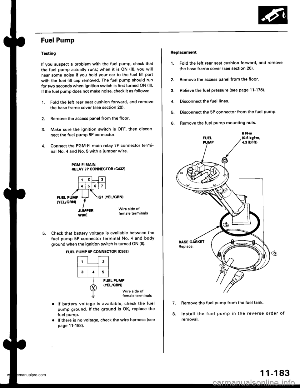
lf you suspect a problem with the fuel pump, check that
the fuel pump actually runs; when it is oN (ll), you will
hear some noise if you hold your ear to the fuel fill port
with the fuel fill cap removed. The fuel pump should run
for two seconds when ignition switch is first turned ON (ll).
lf the fuel pump does not make noise, check it as follows:
1. Fold the left rear seat cushion forward, and remove
the base frame cover (see section 20).
2, Remove the access panel from the floor.
3. Make sure the ignition switch is OFF, then discon-
nect the fuel pumP 5P connector.
4. Connect the PGM-FI main relay 7P connector termr-
nal No. 4 and No, 5 with a jumper wire.
PGM.FI MAINRELAY 7P CONNECTOR (Cit:}2l
I'TtlJilt f -r'-r ll.l5l517l,frTt-,at\FUEL pUMp Lr- . tcl tyEL/cRNl
rYEL/cRNl IIJUMPER Wir€ side of
WIRE female terminals
5. Check that battery voltage is available between the
fuel pump 5P connector terminal No. 4 and body
ground when the ignition switch is turned ON (ll).
FUEL PUMP 5P CONNECTOR {C562}
12
3a5
lf battery voltage is available, check the fuel
pump ground. lf the ground is OK, replace the
fuel oumo.
lf there is no voltage, check the wire harness (see
page 11-188).
FUEL PUMP(YEL/GRNI
wire side offemale terminals
Raplac6mont
1. Fold the left rear seat cushion forward, and remove
the base frame cover (see section 20).
2. Remove the access panel from the floor.
3, Relieve the fuel pressure (see page 11-178).
4. Disconnect the fuel lines.
5. Disconnect the 5P connector from the fuel pump.
6. Remove the fuel pump mounting nuts.
7. Remove the fuel pump from the fuel tank.
Install the fuel pump in the reverse order of
removal.
8.
11-183
www.emanualpro.com
Page 389 of 1395
PGM-FI Main Relay
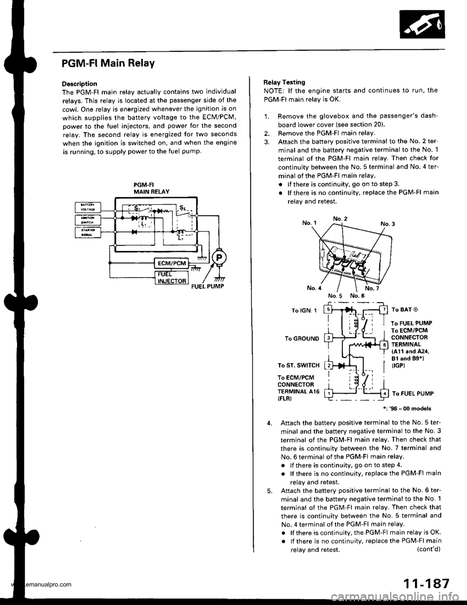
Description
The PGM-Fl main relav actuallv contains two individual
relays. This relay is located at the passenger side of the
cowl. One relay is energized whenever the ignition is on
which supplies the battery voltage to the ECM/PCM,
power to the fuel injectors, and power for the second
relay. The second relay is energized for two seconds
when the ignition is switched on, and when the engine
is running, to supply power to the fuel pump
PGM.FIMAIN RELAY
Belay Testing
NOTE: lf the engine starts and continues to run, the
PGM-FI main relay is OK.
1. Remove the glovebox and the passenger's dash-
board lower cover (see section 20).
2. Remove the PGM-FI main relay
3. Aftach the battery positive terminal to the No. 2 ter-
minal and the battery negative terminal to the No. 1
terminal of the PGM-Fl main relay. Then check for
continuity between the No. 5 terminal and No. 4 ter-
minal of the PGM-FI main relay
. lfthere is continuity, go on to step 3.
. lf there is nocontinuity, replacethe PGM-Fl main
relav and retest.
No.2
To lGN. 1
To GROUND
To ST. SWITCH
To ECM/PCMCONNECTORTERMINAL A16(FLR)
To BAT O
To FUEL PUMPTo ECM/PCMCONNECTORTERMINAL(411 and A24,Bl .nd Bgal(IGP)
To FUEL PUMP
98 - 00 models
Attach the batterv Dositive terminal to the No. 5 ter-
minal and the battery negative terminal to the No. 3
termjnal of the PGM-Fl main relay. Then check that
there is continuity between the No. 7 terminal and
No. 6 terminal of the PGM-FI main relay.
. lf there is continuity, go on to step 4.
. lf there is nocontinuity, replacethe PGM-Fl main
relay and retest.
Attach the batterv oositive terminal to the No.6 ter-
minal and the battery negative terminal to the No. 1
terminal of the PGM-Fl main relay. Then check that
there is continuitv between the No. 5 terminal and
No. 4 terminal of the PGM-Fl main relay.
. lf there is continuity, the PGM-Fl main relay is OK.
. lf there is nocontinuity, replacethe PGM-FI main
5.
(cont'd)
11-147
No.5 No.5
relay and retest.
www.emanualpro.com
Page 390 of 1395
![HONDA CR-V 1997 RD1-RD3 / 1.G Workshop Manual
Fuel Supply System
PGM-FI Main Relay (contdl
Troubleshooting
lc(}21PGM.FI MAIN RELAY 7P CONNECTOR
GND
trTr]--Flq
FI,TilI A
Y
Wire side ot female terminals
- Engine will not start.- InsDection ol PG HONDA CR-V 1997 RD1-RD3 / 1.G Workshop Manual
Fuel Supply System
PGM-FI Main Relay (contdl
Troubleshooting
lc(}21PGM.FI MAIN RELAY 7P CONNECTOR
GND
trTr]--Flq
FI,TilI A
Y
Wire side ot female terminals
- Engine will not start.- InsDection ol PG](/img/13/5778/w960_5778-389.png)
Fuel Supply System
PGM-FI Main Relay (cont'dl
Troubleshooting
lc(}21PGM.FI MAIN RELAY 7P CONNECTOR
GND
trTr]--Flq
FI,Til'I A
Y
Wire side ot female terminals
- Engine will not start.- InsDection ol PGM-FI mainrelay and relay harness,
Check fo. an open in the wireIGND linol:1. Turn the ignition switch OFF.2. Disconnect the PGM Fl mainrelay 7P connector.3. Check for continuity betweenthe PGM'FI main relay 7P con-nector terminal No. 3 and bodyground.
Repair opcn in th€ wire betweenthe PGM-FI main relav and G101.
Check tor an open or short in thewiro (BAT line):Measure voltage between thePGM'FI main relay 7P connectorterminal No. 7 and body ground.- Repai. open or short in lhewir6 belween the PGM-FImain relay and the Fl E/M (15Al fu3e.- Replace th6 FIE/M (15 Altus6in th€ under-hood fuse/.6lay
ls there baftery voltage?
Check lor an open or short in thewire (lGl line):L Turn the ignition switch ON (ll).2. Measure the voltage betweenthe PGM-FI main relay 7P connectorterminal No. 5 and bodyground.- Repair open or shorl in thewire between the FGM-FI mainrelay and the No. 13 FUELPUMP 115 A) tuse.- Replaco the No. 13 RJEL PUMP115 A) luse in the und6.-d$hfuso/ relav box.Check for an open or short in thewire {STS line):1. Turn the ignition switch to theSTART (lll) position.NOTE:. M/T: Clutch pedal must bedepressed.. A/T: Transmission in E orElposition.2. Measure the voltage betweenthe PGM-Fl main retay 7Pconnector terminal No. 2 andbody ground.- Repair open or short in thewire betwe€n the PIGM-FI m.inrclay and th€ No. 31 STARTERSlGllAL 17.5 A) tuse.- Repl.ce the No. 31 STARTERSIGNAL 17.5 Al tuse in theunder-dash tuse/relay box.('97 model: To page 11-189)('98 00models:To page 1l 190)
1 1-188
www.emanualpro.com