set clock HONDA CR-V 1997 RD1-RD3 / 1.G Workshop Manual
[x] Cancel search | Manufacturer: HONDA, Model Year: 1997, Model line: CR-V, Model: HONDA CR-V 1997 RD1-RD3 / 1.GPages: 1395, PDF Size: 35.62 MB
Page 37 of 1395
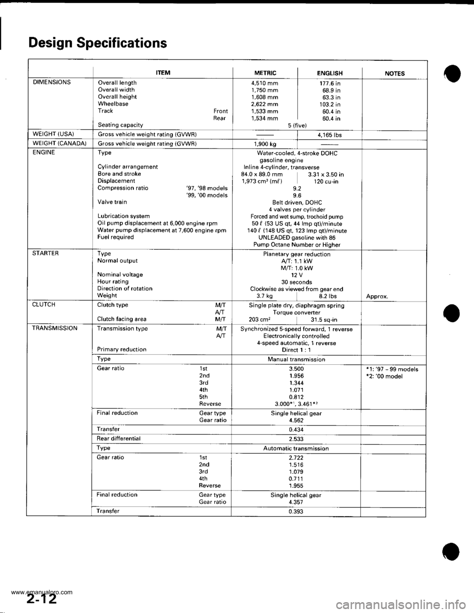
Design Specifications
ITEMMETRICENGLISHNOTES
DIMENSIONSOverall lengthOverallwidthOverall heightWheelbaseTrack FrontRearSeating capacity
4,510 mm1,750 mm1,608 mm2,622 mrn1,533 mm1,534 mm5lf
177.6 in68.9 in63.3 in103.2 in60.4 in60.4 in
WEIGHT (USA)Gross vehicle weight rating (GVWR)| 4,165 tbs
WEIGHT (CANADA)Gross vehicle weight rating (GVWR)1,900 kg
ENGINEType
Cylinder arrangementBore and strokeDisplacementCompression ratio '97,'98 mooers'99, '00 modelsValve train
Lubrication systemOil pump displacement at 6,000 engine rpmWater pump displacement at 7,600 engine rpmFuel required
Water-cooled, 4-stroke DOHCgasoline engineInline 4-cylinder, transverse84.0 x 89.0 mm.1,973 cm3 (m{)
9.2
3.31 x 3.50 in120 cu-in
9.6Belt driven, DOHC4 valves per cylinderForced and wet sump, trochoid pump501 (53 US qt,44 lmp qt)/minute1401 (148 US qt, 123 lmp qt)/minuteUNLEADED gasoljne with 86Pump Octane Number or Higher
STARTERTypeNormal output
NominalvohageHour ratingDirection of rotationWeight
Planetary gear reductionA/T: 1.1 kWM/T: 1.0 kW12V30 secondsClockwise as viewed from gear end3.7 kg 8.2 lbsApprox.
CLUTCHClutch type
Clutch lacing area
MIT
MIT
Single plate dry, diaphragm springTorque converter203 cm, 31.5 sq-in
TRANSMISSIONTransmission type
Primary redLrction
MITSynchronized s-speed torward, 1 reverseElectronically controlled4-speed automatic, 1 reverseDirect I : 1
TypeManualtransmission
Gear ratio 1st2nd3rd4th5thReverse
3.5001.9561.3441.0710.8123.000*,. 3.461*'
*1: '97 - 99 models*2: '00 model
Final reduction Gear typeGear rataoSingle helical gear4.562
Transfer0.434
Rear differential2.533
TypeAutomatic transmission
Gear ratio 1st2nd3rd4thReverse
2.722
1.0790.7111.955
Final reduction Gear typeGear ratioSingle helical gear4.357
Transfer0.393
2-12
www.emanualpro.com
Page 66 of 1395

lgnition System
5.
lgnition Timing Inspection and Setting
2.
1.Check the idle speed, and adjust it if necessary (see
section 1 1).
Pull out the service check connector 2P (BRN and
BLK wires) from the connector holder located under
the dash on the front passenger side, then connect
the scs service connector (P/N 07PAz - 0010100) to
it.
Start the engine. Hold the engine at 3,000 rpm with
no load (A/T in N or E, Mff in neutral) until the
radiator fan comes on, then let it idle.
Connect the timing light to the No. I ignition wire,
then point the light toward the pointer on the timing
belt cover.
Check the ignition timing in no load conditions:
headlights, blower fan, rear window defogger, and
air conditioner are not operating.
lgnition Timing:
M/T: 16" 12" BTDC (RED) idling in neutral
AlTt'16" !2" BTDC (RED) idling in E or E
CRANKSHAFTPULLEY
4-16
6. lf necessary, adjust the ignition timing as follows.
Loosen the distributor mounting bolts, and turn the
distributor ignition (Dl) housing counterclockwise to
advance the timing or clockwise to retard the tim-
t no,
7.
8.
MOUNTING BOLTS24 N.m {2.4 kgf m, 17 lbtft}
Tighten the distributor mounting bolts, and recheck
the ignition timing.
Disconnect the SCS service connector from the ser-
vice check connector.
To RETARD
www.emanualpro.com
Page 122 of 1395
1.
2.
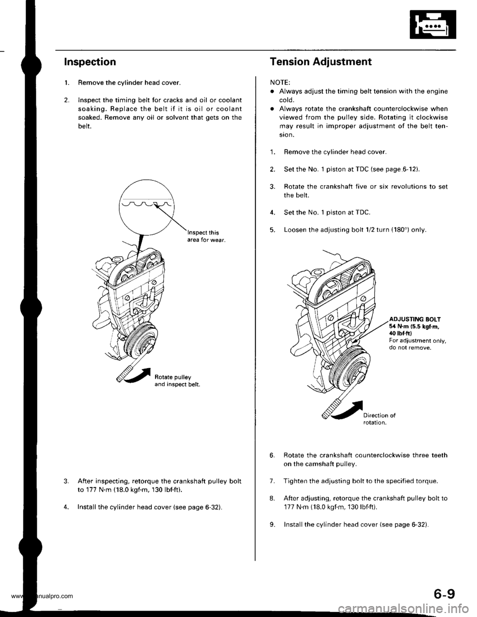
Inspection
Remove the cylinder head cover.
lnspect the timing belt for c.acks and oil or coolant
soaking. Replace the belt if it is oil or coolant
soaked. Remove any oil or solvent that gets on the
belt.
lnspect thisarea for wear.
After inspecting, retorque the crankshaft pulley bolt
to 177 N.m (18.0 kgnm, 130 lbf.ft).
Install the cylinder head cover (see page 6-32).
3.
Tension Adjustment
NOTE:
. Always adjust the timing belt tension with the engine
coto.
. Always rotate the crankshaft counterclockwise when
viewed from the pulley side. Rotating it clockwise
may result in improper adiustment of the belt ten-
sion.
'1. Remove the cylinder head cover
2. Set the No. 1 piston at TDC (see page.6-12).
3. Rotate the crankshaft five or six revolutions to set
the belt.
Set the No. 1 piston at TDC.
Loosen the adjusting bolt 1/2 turn (180') only.
4.
5.
ADJUSTING BOLT5,4 N.m (5.5 kgf.m,40 tbtftlFor adiustment only,
7.
8.
Rotate the crankshaft counterclockwise three teeth
on the camshaft pulley.
Tighten the adjusting bolt to the specified torque.
After adjusting, retorque the crankshaft pulley bolt to
177 N.m (18.0 kgf.m, 130 lbf.ft).
Installthe cylinder head cover (see page 6-32).9.
rotation,
6-9
www.emanualpro.com
Page 166 of 1395
PistonsCrankshaft
Installation
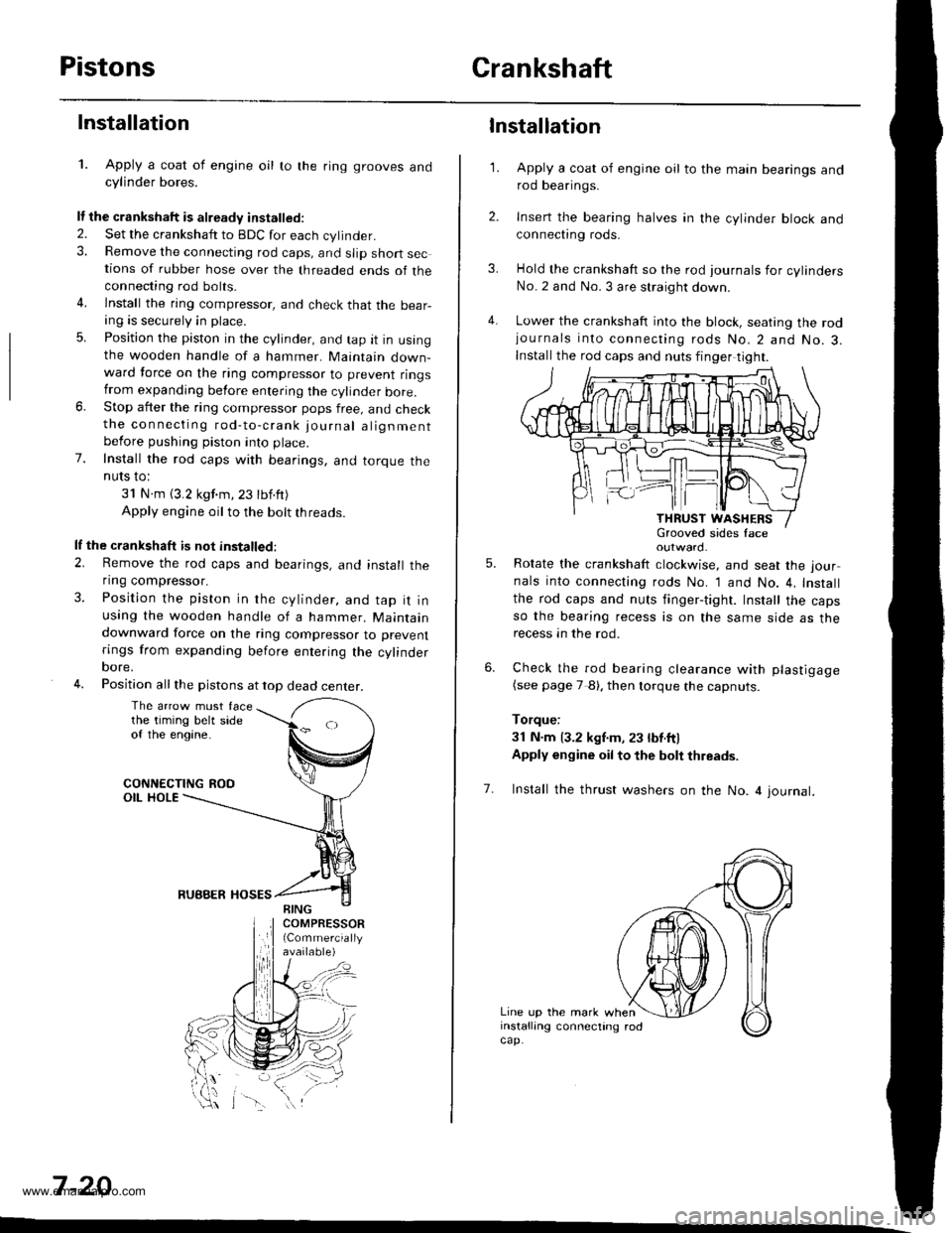
1. Apply a coat of engine oil to the ring grooves andcylinder bores.
It the crankshaft is already installed.
2. Set the crankshatt to BDC for each cylinder.3. Remove the connecting rod caps, and slip short sections of rubber hose over the threaded ends of theconnecting rod bolts.
4. lnstall the ring compressor, and check that the bear-ang is securely in place.
5. Position the piston in the cylinder, and tap it in usingthe wooden handle of a hammer. Maintain down-ward force on the ring compressor to prevent ringstrom expanding before entering the cylinder bore.6. Stop after the ring compressor pops free, and checkthe connecting rod-to-crank journal alignmentbefore pushing piston into place.
7. Install the rod caps with bearings, and torque theNUIS IO:
31 N.m (3.2 kgf.m,23 tbf.ft)
Apply engine oil to the bolt threads.
lf the crankshaft is not installed:
2. Remove the rod caps and bearings, and install theflng compressor.
3. Position the piston in the cylinder, and tap it inusing the wooden handle of a hammer. Maintaindownward force on the ring compressor to prevent
rings from expanding before entering the cylinderoore,
4. Position all the pistons at top dead center.
The arrow must facethe timing belt sideof the engine.
CONNECTING ROOOIL HOLE
RUBBER HOSES
7 -20
\-\
3.
4.
1.
6.
Installation
Apply a coat of engine oil to the main bearings androd bearings.
Insert the bearing halves in the cylinder block andconnect|ng rods.
Hold the crankshaft so the rod journals for cylindersNo.2 and No. 3 are straight down.
Lower the crankshaft into the block, seating the rodjournals into connecting rods No.2 and No.3.Install the rod caps and nuts finger tight.
outward.
Rotate the crankshaft clockwise, and seat the jour
nals into connecting rods No. 1 and No. 4, Install
the rod caps and nuts finger-tight. Install the capsso the bearing recess is on the same side as therecess an the rod.
Check the rod bearing clearance with plastigage(see page 7 8). then lorque the capnuts.
Torque:
3l N.m 13.2 kgf.m, 23 lbt.ftl
Apply engine oil to the bolt thleads.
5.
7. Install the thrust washers on the No. 4 journal.
Line up the mark wheninstalling connecting rodcap.
www.emanualpro.com
Page 572 of 1395
Troubleshooting Procedures
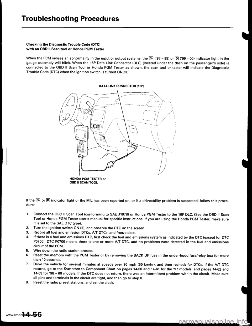
Checking ths Diagnostic Trouble Code (DTC)
with an O8D ll Scan tool or Honda PGM Tsster
When the PCM senses an abnormality in the input or output systems, the El ('97 - 98) or E ('99 - O0) indicator light in thegauge ass€mbly will blink. When the 16P Data Link Connector (DLC) {located under the dash on the passenger's side) is
connected to the OBD ll Scan Tool or Honda PGM Tester as shown, the scan tool or tester will indicate the Diagnostic
Trouble Code (DTC) when the ignition switch is turned ON(ll).
HONDA PGM TESTER olOBD II SCAN TOOL
lf the E or E indicator light or the MIL has been reported on, or if a driveability problem is suspected, follow this proce-
dure:
1. Connect the OBD ll Scan Tool (conforming to SAE J1978) or Honda PGM Tester to the 16P DLC. (See the OBD ll ScanTool or Honda PGM Tester user's manual for specific instructions. lf you are using the Honda PGM Tester, make sureit is set to the SAE DTC Wpe).2. Turn the ignition switch ON (ll), and observe the DTC on the screen
3. Record allfuel and emission DTCS, A,,/T DTCS, and freeze data.
4. lf there is a fuel and emissions DTC, first check the fuel and emissions system as indicated by the DTC (except for DTCP0700). DTC P0700 means there is one or more Ay'T DTC, and no Droblems were detected in the fuel and emissionscircuit of the PCM.
5. Wire down the radio station presets.
6. Reset the memory with the PGM Tester o. by removing the BACK UP fuse in the under-hood fuse/relay box for morethan 10 seconds.
7. Drive the vehicle for several minutes at speeds over 30 mph (50 km/hr), and then recheck for DTCS. lf the A/T DTCreturns, 9o to the Symptom-to Component Chart on pages 14-60 and 14-61 for the '97 models, and pages 14-62 and14-63 for '98 - 00 models. lf the OTC does not return, there was an intermittent problem within the circuit. Make sureall pins and terminals in the circuit are tight, and then go to step 8.8. Reset the radio Dreset stations, and set the clock.
DATA LINK CONNECTOR {16PI
[ -=.r,
ili,i /i,
v,., i
14-56
www.emanualpro.com
Page 575 of 1395
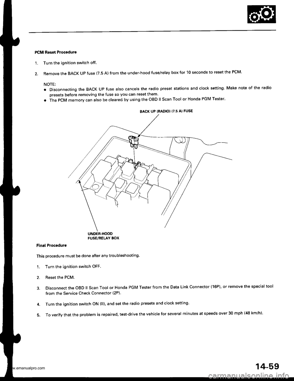
PCM Reset Procedure
'1. Turn the ignition switch off
2. Remove the BACK UP fuse (7.5 A) from the under-hood fuse/relay box for 10 seconds to reset the PCM.
NOTE:
. Disconnecting the BACK Up fuse also cancels the radio preset stations and clock setting Make note of the radio
presets before removing the fuse so you can reset them
. The PCM memorv can also be cleared by using the OBD ll Scan Tool or Honda PGM Tester'
UNDER.HOODFUSE/RELAY BOX
Final Proceduro
This procedure must be done after any troubleshooting.
1. Turn the ignition switch OFF.
2. Reset the PCM.
3. Disconnect the OBD ll Scan Tool or Honda PGM Tester from the Data Link Connector (16P), or remove the special tool
from the Service Check Connector (2P).
4. Turn the ignition switch ON (ll), and set the radio presets and clock setting'
5, To verify that the problem is repaired. test-drive the vehicle for several minutes at speeds over 30 mph (48 km/h).
BACK UP IRADIO} {7.5 AI FUSE
14-59
www.emanualpro.com
Page 1390 of 1395
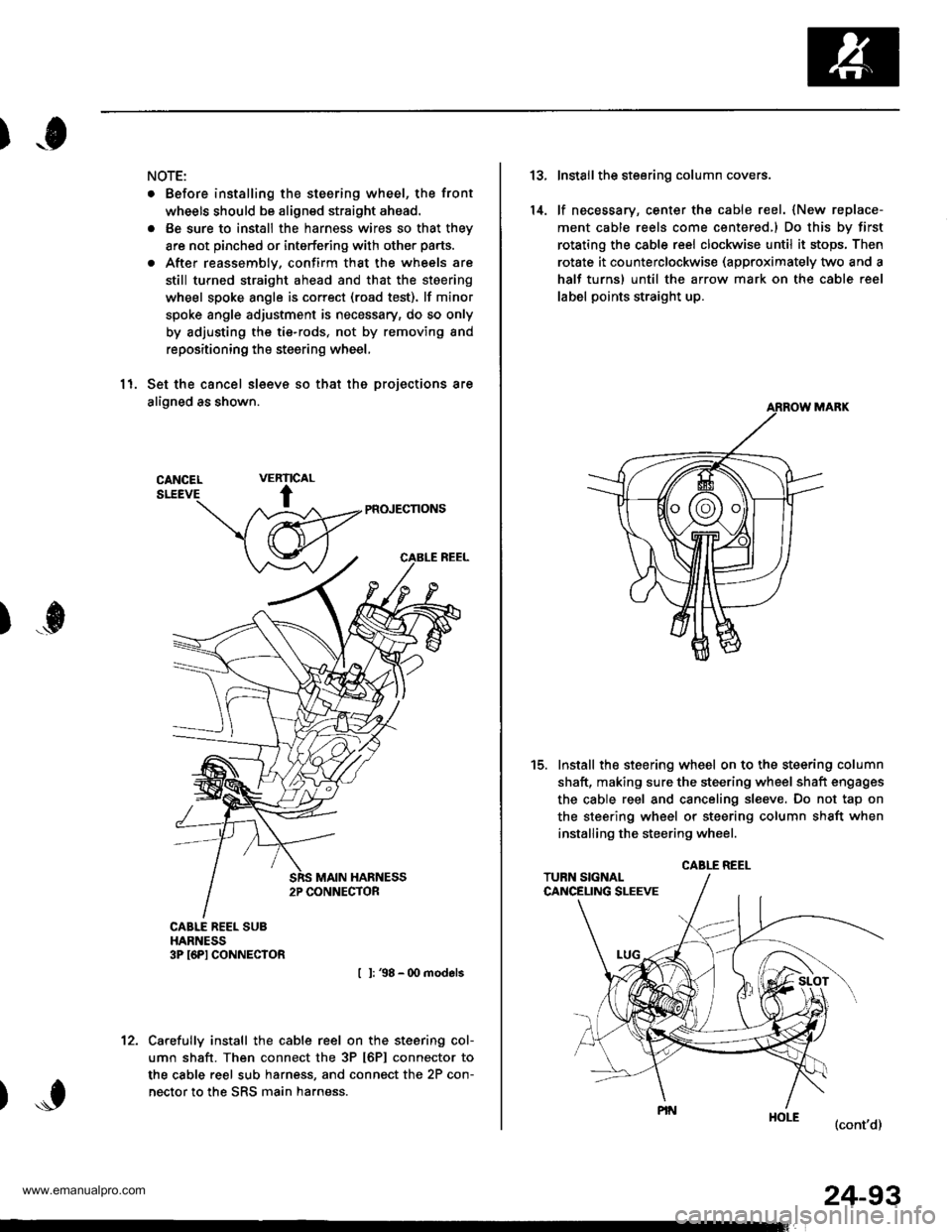
)o
NOTE:
. Before installing the steering wheel, the front
wheels should be aligned straight ahead.
. Be sure to install the harness wires so that they
are not pinched or interfering with other parts.
. After reassemblv, confirm that the wheels are
still turned straight ahead and that the steering
wheel spoke angle is correct (road test). lf minor
spoke angle adjustment is necessary, do so only
by adjusting the tie-rods, not by removing and
repositioning the steering wheel,
11. Set the cancel sleeve so that the projections are
aligned as shown.
PR(NECNONS
I l: 38 - 00 models
Carefully install the cable reel on the steering col-
umn shaft. Then connect the 3P t6Pl connector to
the cable reel sub harness, and connect the 2P con-
nector to the SRS main harness.
RIC
t
VEAL
)...0
't2.
24-93
13.
14.
Install the steering column covers.
lf necessary, center the cable reel. {New replace-
ment cable reels come centered,l Do this by first
rotating the csble reel clockwise until it stops, Then
rotate it counterclockwise (approximately two and a
half turns) until the arrow mark on the cable reel
label points straight up.
Install the steering wheel on to the steering column
shaft, making sure the steering wheel shaft engages
the cable reel and canceling sl€eve. Do not tap on
the steering wheel or steering column shaft when
installing the steering wheel.
(cont'd)
t5.
CABLE REEL
www.emanualpro.com