top Engine nut HONDA CR-V 1997 RD1-RD3 / 1.G Workshop Manual
[x] Cancel search | Manufacturer: HONDA, Model Year: 1997, Model line: CR-V, Model: HONDA CR-V 1997 RD1-RD3 / 1.GPages: 1395, PDF Size: 35.62 MB
Page 123 of 1395
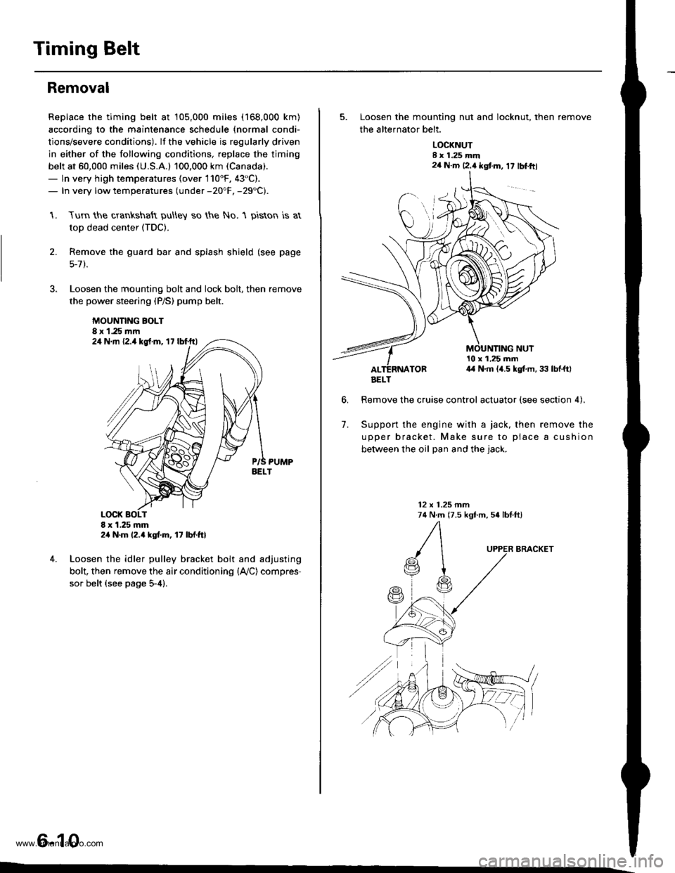
Timing Belt
Removal
Replace the timing belt at 105,000 miles (168,000 km)
according to the maintenance schedule {normal condi-
tions/severe conditions). lf the vehicle is regularly driven
in either of the following conditions, replace the timing
belt at 60,000 miles (U.S.A.l 100.000 km (Canada).
- ln very high temperatures (over 110'F, 43"C).- In very low temperatures (under -20"F. -29"C).
Turn the crankshaft pu\ley so the No. 1 piston is at
top dead center (TDC).
Remove the guard bar and splash shield (see page
5-7 ).
Loosen the mounting bolt and lock bolt. then remove
the power steering (P/S) pump belt.
MOUNNNG BOLT8 x 1.25 rnm
1.
2.
,l
4. Loosen the idler pulley bracket bolt and adjusting
bolt, then remove the air conditioning (lVC) compres
sor belt (see page 5-4).
6-10
24 N.m {2.4 kgt.m, 17 lbf.ftl
24 N.m 12.4 kgf.m, lt lbf.ftl
5. Loosen the mounting nut and locknut, then remove
the altefnator belt.
LOCKNUTI x 1.25 mm2a N.m 12.4 kgt m, 17 lblftl
6.
10 x 1,25 mm4,1 N.m (,1.5 kgt m, 33 lbtftl
Remove the cruise control actuator (see section 4).
Support the engine with a jack, then remove the
upper bracket. Make sure to place a cushion
between the oil Dan and the iack.
12 x 1.25 mm74 N.m (7.5 kgf m, 54 lbtftl
7.
BRACKET
AELT
www.emanualpro.com
Page 146 of 1395
21.
22.
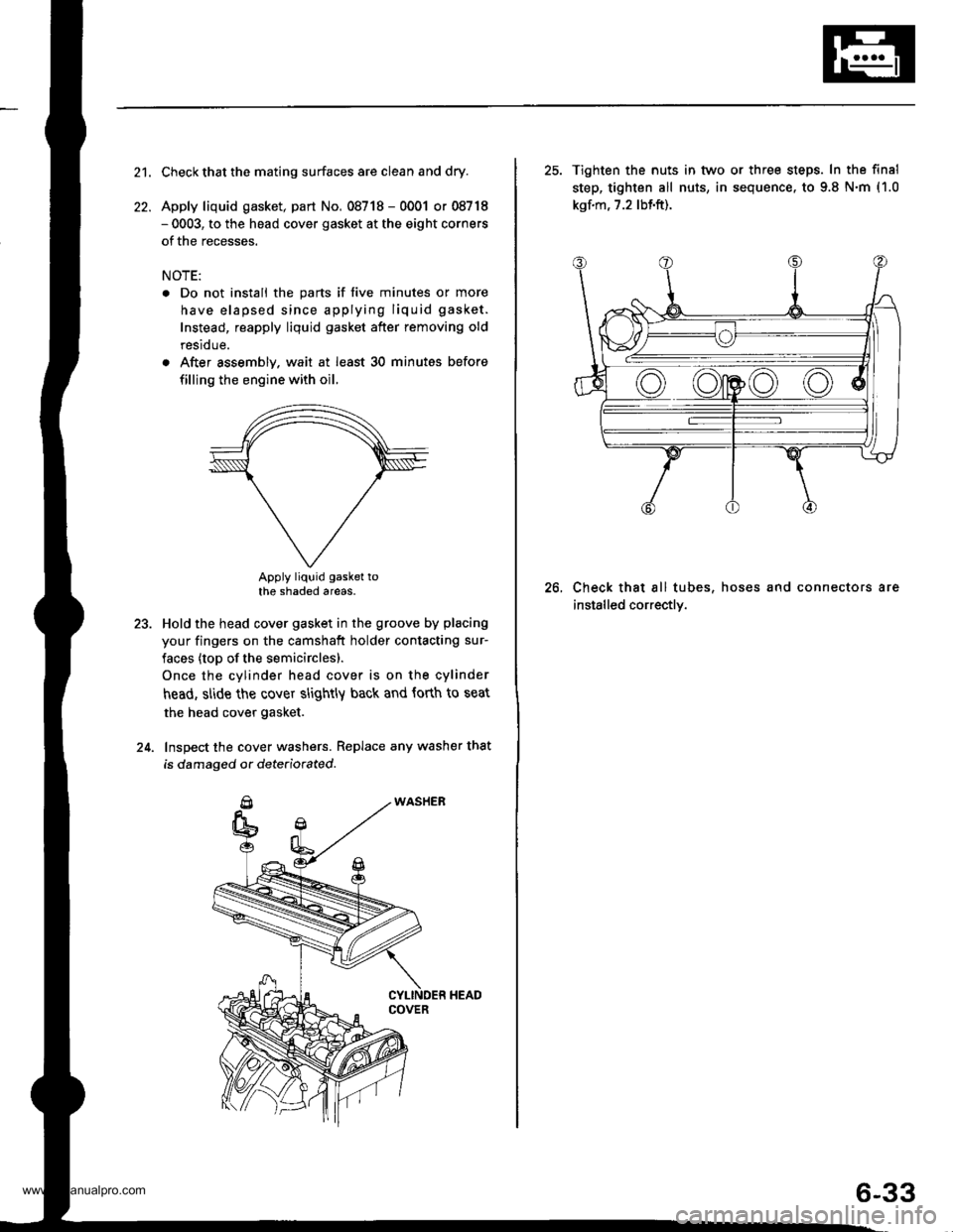
Check that the mating surfaces are clean and dry.
Apply liquid gasket, part No. 08718 - 0001 or 08718- 0003, to the head cover gasket at the eight corners
of the recesses.
NOTE:
. Do not install the parts if five minutes or more
have elapsed since applying liquid gasket.
Instead, reapply liquid gasket after removing old
residue.
. After assembly. wait at least 30 minutes before
filling the engine with oil.
Apply liquid gasket tothe shaded areas.
Hold the head cover gasket in the groove by placing
your fingers on the camshaft holder contacting sur-
faces (top of the semicirclesl.
Once the cylinder head cover is on the cylinder
head, slide the cover slightly back and forth to seat
the head cover gasket.
Inspect the cover washers. Replace any washer that
is damaged or dete(iorated.
23.
24.
25. Tighten the nuts in tvvo or three steps. In the final
step, tighten all nuts, in sequence. to 9.8 N.m (1.0
kgf.m, 7.2 lbf.ft).
Check that all tubes, hoses and connectors are
installed correctly.
26.
6-33
www.emanualpro.com
Page 150 of 1395
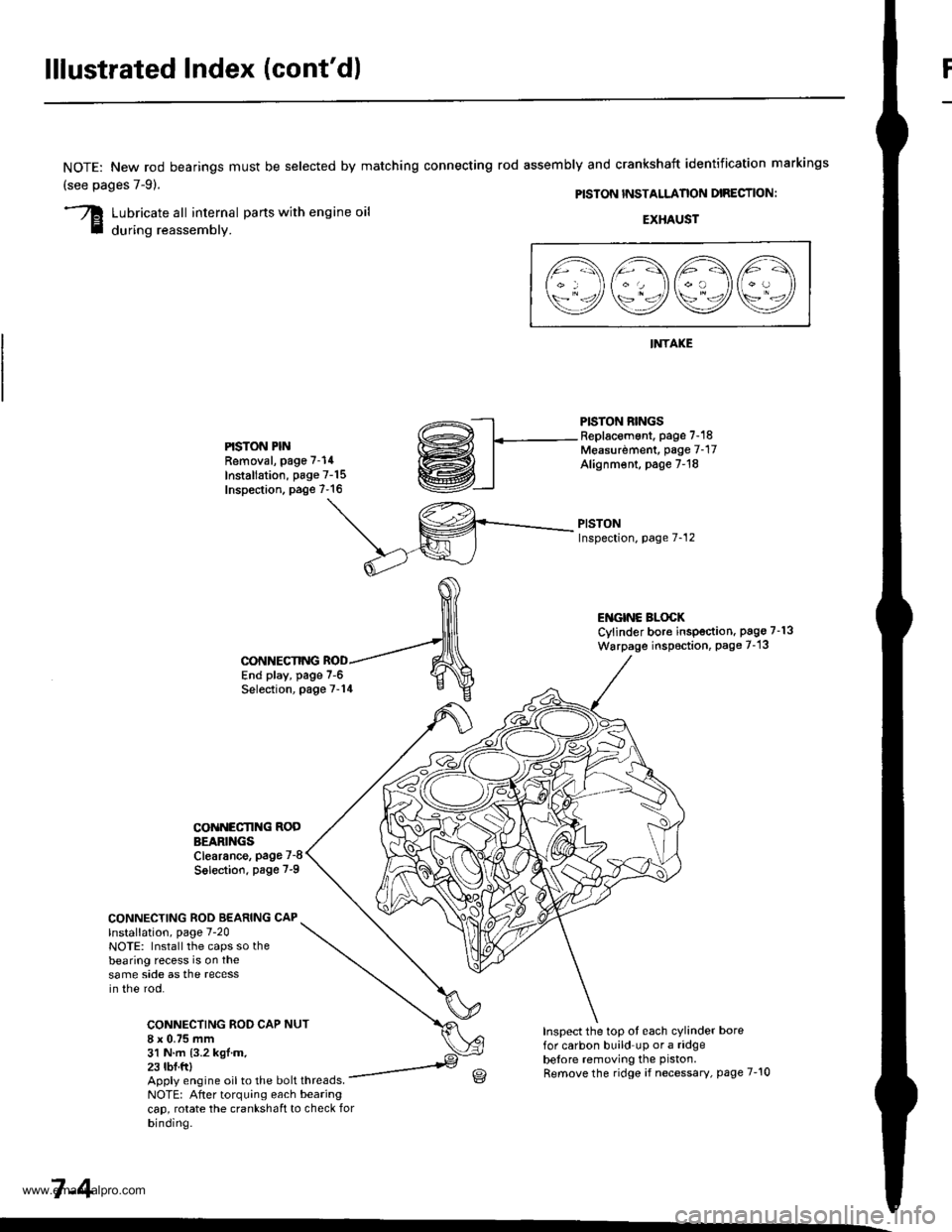
lllustrated Index (cont'd)
NOTE: New rod bearings
(see pages 7-91.
must be selected by matching connecting rod assembly and crankshaft identification markings
PISTON INSTALLANON DIRECTION:
Lubricate all internal parts with engine oil
during reassembly.EXHAUST
INTAKE
PISTON RINGSReplacement. page 7-18Measurdment, page 7-17Alignm€nt, page 7-18
PISTONInspection, page 7-12
l1\AAtr\
\9q9Q9e/
PISTON PINRemoval, page 7-14
Installation, page 7-15Inspection. page 7-16
ENGINC BLOCKCylinder bore inspection. pago 7-13
Warpage inspoction, Page 7-'13
CONNECTING ROD BEARING CAPlnstallation, page 7-20NOTE: Install the caps so thebearing recess is on thesame side as the recessin the rod.
CONNECTING ROD CAP8 x 0.75 mm31 N.m {3.2 kgl.m.23 tbf.ftl
CONNECTING
COiINECI'ING RODBEARINGSClearance, page 7-8
Solection. page 7-9
NUT
End play, page 7-6Selection, page 7-14
Inspect the top ot each cylinder borefor carbon build up or a ridgebelore removing the piston.
Remove the ridge if necessary, page 7-10Apply engine oil to the bolt threads.NOTE: After torquing each bearingcap, rotate the crankshaft to check forbinding.
7-4
www.emanualpro.com
Page 166 of 1395
PistonsCrankshaft
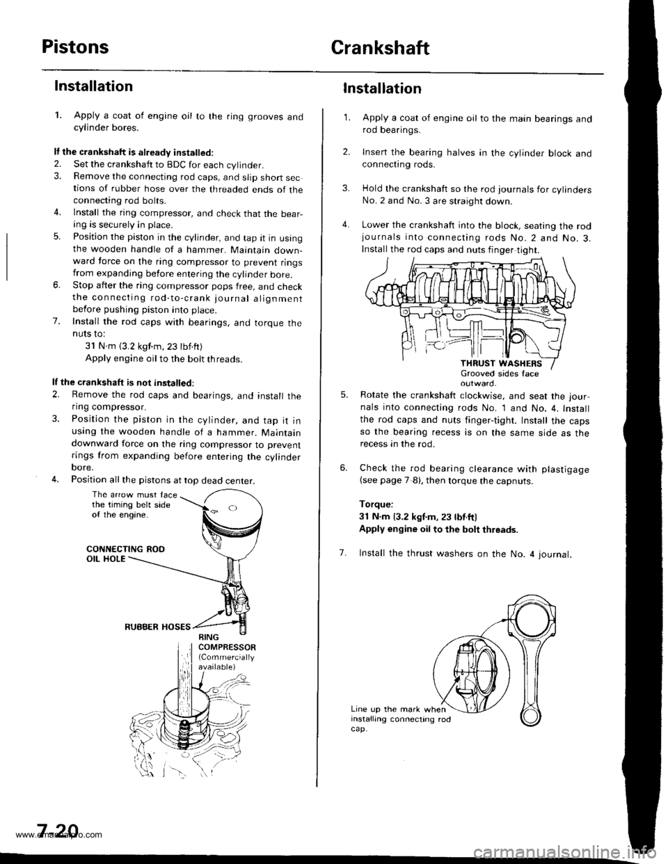
Installation
1. Apply a coat of engine oil to the ring grooves andcylinder bores.
It the crankshaft is already installed.
2. Set the crankshatt to BDC for each cylinder.3. Remove the connecting rod caps, and slip short sections of rubber hose over the threaded ends of theconnecting rod bolts.
4. lnstall the ring compressor, and check that the bear-ang is securely in place.
5. Position the piston in the cylinder, and tap it in usingthe wooden handle of a hammer. Maintain down-ward force on the ring compressor to prevent ringstrom expanding before entering the cylinder bore.6. Stop after the ring compressor pops free, and checkthe connecting rod-to-crank journal alignmentbefore pushing piston into place.
7. Install the rod caps with bearings, and torque theNUIS IO:
31 N.m (3.2 kgf.m,23 tbf.ft)
Apply engine oil to the bolt threads.
lf the crankshaft is not installed:
2. Remove the rod caps and bearings, and install theflng compressor.
3. Position the piston in the cylinder, and tap it inusing the wooden handle of a hammer. Maintaindownward force on the ring compressor to prevent
rings from expanding before entering the cylinderoore,
4. Position all the pistons at top dead center.
The arrow must facethe timing belt sideof the engine.
CONNECTING ROOOIL HOLE
RUBBER HOSES
7 -20
\-\
3.
4.
1.
6.
Installation
Apply a coat of engine oil to the main bearings androd bearings.
Insert the bearing halves in the cylinder block andconnect|ng rods.
Hold the crankshaft so the rod journals for cylindersNo.2 and No. 3 are straight down.
Lower the crankshaft into the block, seating the rodjournals into connecting rods No.2 and No.3.Install the rod caps and nuts finger tight.
outward.
Rotate the crankshaft clockwise, and seat the jour
nals into connecting rods No. 1 and No. 4, Install
the rod caps and nuts finger-tight. Install the capsso the bearing recess is on the same side as therecess an the rod.
Check the rod bearing clearance with plastigage(see page 7 8). then lorque the capnuts.
Torque:
3l N.m 13.2 kgf.m, 23 lbt.ftl
Apply engine oil to the bolt thleads.
5.
7. Install the thrust washers on the No. 4 journal.
Line up the mark wheninstalling connecting rodcap.
www.emanualpro.com
Page 372 of 1395

ldle Control System
ldle Speed Setting (cont'd)
38 - 0O mod6l3:
NOTE: Before setting the idle speed, check the follow-
ing items:- The MIL has not been reported on.- lgnition timing- Spark plugs
- Air cleaner- PCV system
1. Start the engine. Hold the engine at 3.000 rpm with
no load (in Park or neutral) until the radiator fan
comes on, then let it idle.
Connect a tachometer.
Disconnect the IAC valve 2P connector and the EVAP
purge control solenoid valve 2P connector.
CONTROLSOLENOID VALVE
SOLENOID VALVE
lf the engine stalls, restart the engine with the accel-
erato. pedal slightly depressed. Stabilize the rpm at
1,000, then slowly release the pedal until the engine
idles.
Che€k the idle in no-load conditions: headlights, blow-
er fan, rear defogger, radiator fan, and air conditioner
are not operating,
ldle speed should bo:
480 t 50 rpm {in PErk or noutrall
11-170
lf necessary, adjust the idle speed, by turning the
idle adjusting screw.
After adjusting the idle speed, recheck the ignition
timing (see section 4). lf it is out of spec, go back to
steo 4.tDt.E
6. Turn the ignition switch OFF.
7. Reconnect the 2P connectors to the IAC valve and
the EVAP purge control solenoid valve, then do the
ECM/PCM reset procedure.
8. Restart and idle the engine with no-load conditions
for one minute, then check the idle speed.
ldle speod should be:,98 model:
750 t 50 rpm tin Park or neutral)'9!l - 00 modsls:
730 i 50 lpm lin Psrk or neutral)
NOTE: lf the idle speed increases to 780 t 50 rpm(770 1 50 rpml*, this means the EVAP system is
purging the canister. To stop the purging temporari-
ly, raise the engine speed above 1,000 rpm with the
accelerator pedal, then slowly release the pedal.*: '99 - 00 models
9. Let the engine idle for one minute with the head-
lights (Low) ON, and check the idle speed.
ldle speed should be:
38 mod6l:
750 f 50 rpm (in Palk or neutrall'99 - 00 modols:
730 t 50 rpm (in Palk or neutral)
10. Turn the headlights off. Let the engine idle for one
minute with the heater fan switch at Hl and air con-
ditioner on, then check the idle speed.
ldls spqed should be:'98 model:
780 t 50 rpm (in Park or neutrall'99 - 00 mod€ls:
7701 50 rpm lin Park or neutral)
lf the idle speed is not within specification. see the
Symptom Chart on page 11-64.
ADJUSTING
www.emanualpro.com
Page 432 of 1395
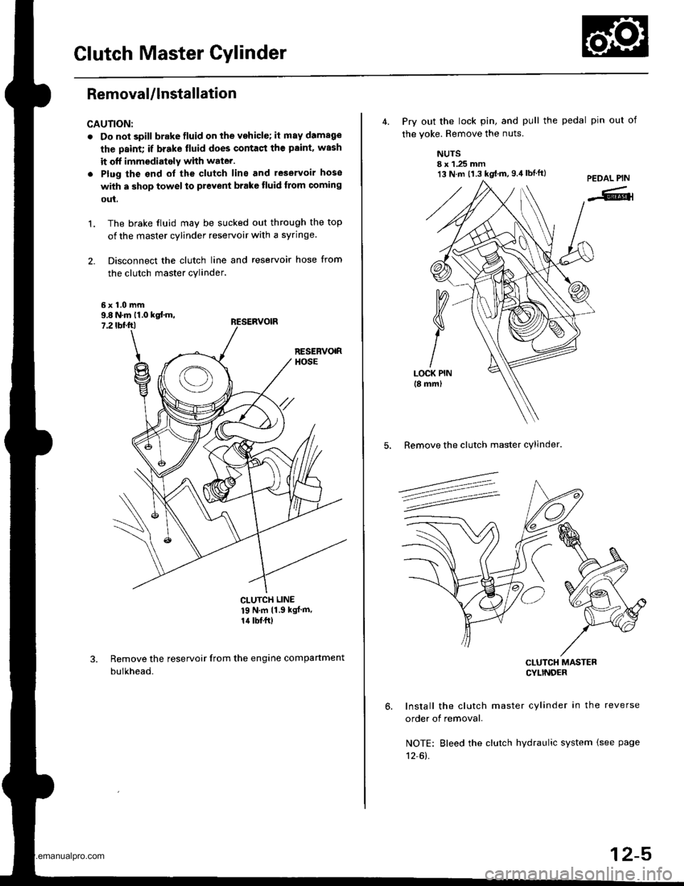
Glutch Master Cylinder
Removal/lnstallation
CAUTION:
. Do not spill brake fluid on the vehicle; it may damage
the paint; if brake tluid does contact the paint. wash
it off immediately with water.
. Plug the end ol the clutch line and leservoir hose
with a shop towel to prevent brake tluid trom coming
out.
The brake fluid may be sucked out through the top
of the master cylinder reservoir with a syringe.
Disconnect the clutch line and reservoir hose from
the clutch master cylinder,
't.
9.8 N.m 11.0 kst m,7.2 tbf.ftl
CLUTCH LINE
19 N'm 11 9 kgJ m'
14 lbf.frl
Remove the reservoir from the engine compartment
bulkhead.
13 N.m t1.3 kgt.m,g.il lbtft)
4. Prv out the lock pin, and pull the pedal pin out of
the voke. Remove the nuts.
NUTSI x 1.25 mm
5, Remove the clutch master cylinder.
CLUTCH MASTERCYLINDEF
Install the clutch master cylinder in the reverse
order of removal.
NOTE: Bleed the clutch hydraulic system {see page
12-61.
12-5
www.emanualpro.com
Page 859 of 1395
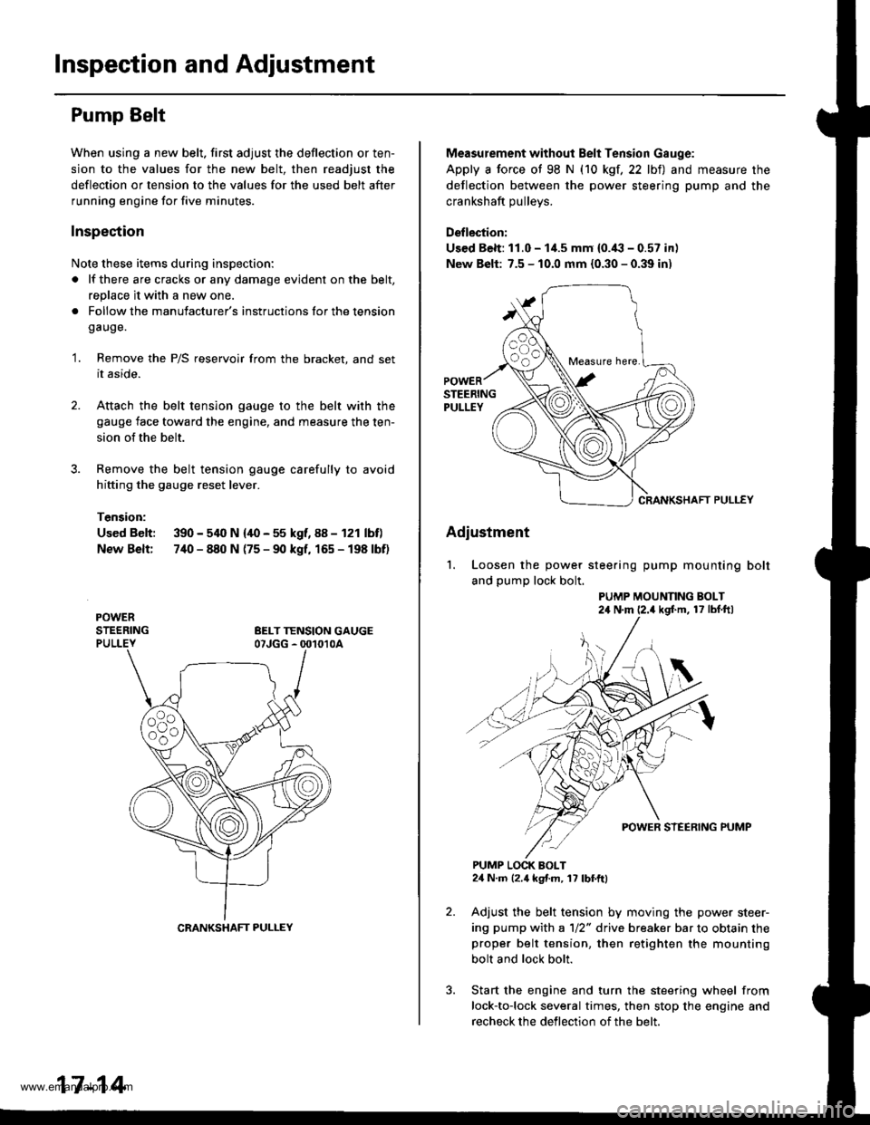
Inspection and Adjustment
Pump Belt
When using a new belt. first adjust the deflection or ten-
sion to the values for the new belt, then readjust the
deflection or tension to the values for the used belt after
running engine for five minutes.
Inspection
Note these items during inspection:
a lf there are cracks or any damage evident on the belt,
replace it with a new one.
. Follow the manufacturer's instructions lor the tension
gauge.
'1. Remove the P/S reservoir from the bracket, and set
it aside.
2. Attach the belt tension gauge to the belt with the
gauge face toward the engine, and measure the ten-
sion of the belt.
Remove the belt tension gauge carefully to avoid
hitting the gauge reset lever.
Tension:
Used Belt: 390 - 540 N {40 - 55 kgf, 88 - 121 lbf)
New Belt: 7,[0 - 840 N (75 - 90 kgf, 165 - 198 lbf)
CRANKSHAFT PULLEY
17-14
Measurement without Belt Tension Gauge:
Apply a force ot 98 N (10 kgf,22 lbt) and measure the
deflection between the power steering pump and the
crankshaft oullevs.
Deflection:
Used Belt: 11.0 - 1i1.5 mm {0.'(l - 0.57 in)
New Belt: 7.5 - 10.0 mm {0.30 - 0.39 in)
CRANKSHAFT PULLEY
Adiustment
'1. Loosen the power steering pump mounting bolt
and pump lock bolt.
PUMP MOUNNNG BOLT24 N'm (2.4 kgf'm, 17 lbf ftl
PUMP LOCK BOLT24 N.m 12.4 kgf.m, 17 lbf.ftl
Adjust the belt tension by moving the power steer-
ing pump with a 1/2" drive breaker bar to obtain theproper belt tension, then retighten the mounting
bolt and lock bolt.
Start the engine and turn the steering wheel from
lock-to-lock several times, then stop the engine and
recheck the deflection of the belt.
Measure here.
www.emanualpro.com
Page 860 of 1395
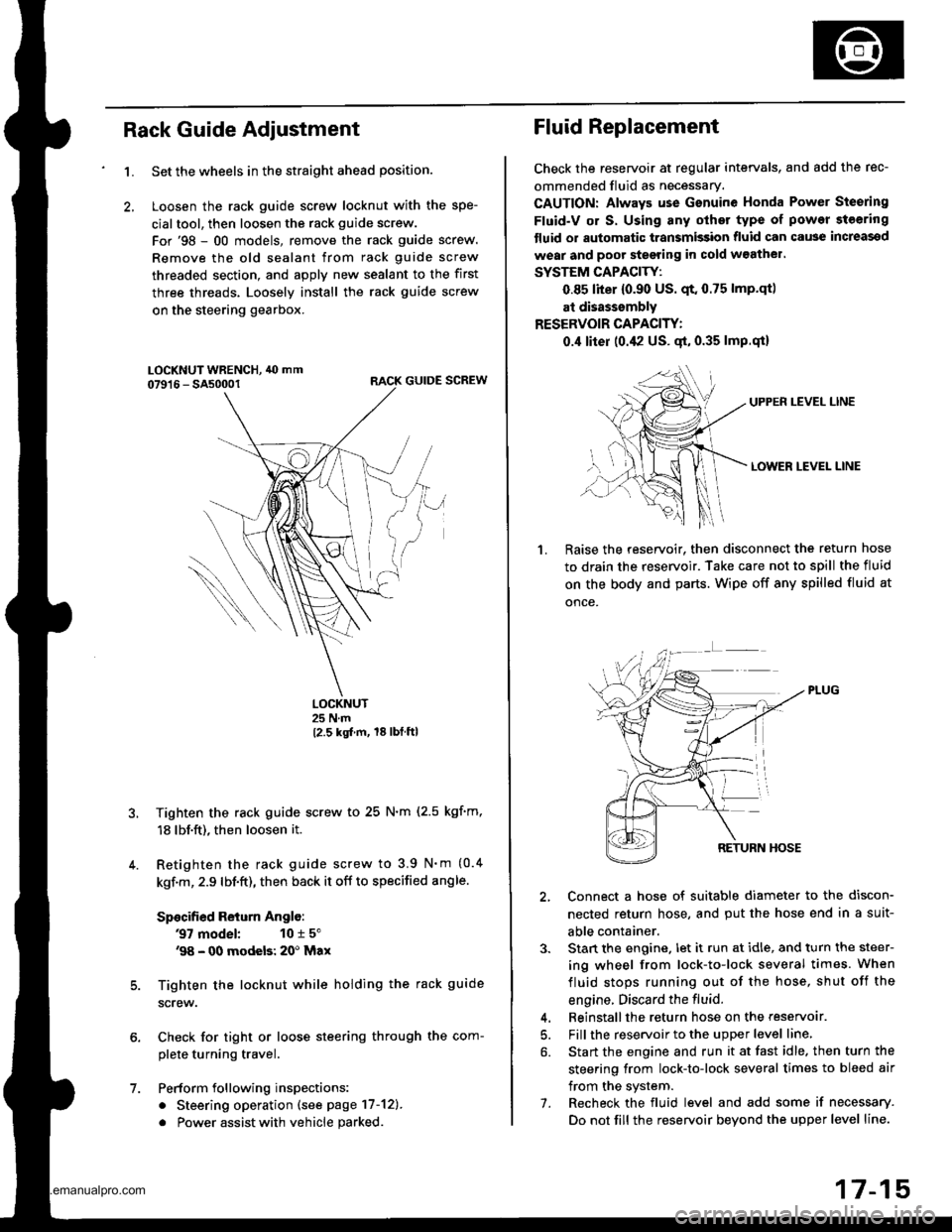
Rack Guide Adjustment
1.
6.
7.
5.
4.
Set the wheels in the straight ahead position.
Loosen the rack guide screw locknut with the spe-
cialtool, then loosen the rack guide screw.
For'98 - 00 models, remove the rack guide screw.
Remove the old sealant from rack guide screw
threaded section, and apply new sealant to the first
three threads. Loosely install the rack guide screw
on the steering gearbox.
RACK GUIDE SCREW
LOCKNUT25 N.m
12.5 kgt m, 18lbtftl
Tighten the rack guide screw to 25 N.m (2.5 kgf'm,
18 lbf.ft), then loosen it.
Retighten the rack guide screw to 3.9 N'm (0.4
kgf.m, 2.9 lbf.ft), then back it off to specified angle.
Specified Return Anglo:
37 model: 10 r 5"'98 - 00 modeb: 20' Max
Tighten the locknut while holding the rack guide
screw.
Check for tight or loose steering through the com-
plete turning travel.
Perform following inspections:
. Steering operation (see page 17-12).
. Power assist with vehicle parked
Fluid Replacement
Check the reseryoir at regular intervals, and add the rec-
ommended fluid as necessary.
CAUTION: Always use Gsnuine Honda Power Steering
Fluid-V or S. Using any other type of power steering
tluid or automatic transmission fluid can cause increassd
wear and poor steering in cold w3athel.
SYSTEM CAPACITY:
0.85 liter {0.90 US. qt. 0.75 lmp.qtl
at disasssmbly
RESERVOIR CAPACITY:
0.,1 liter (0.42 US. gt, 0.35 lmp.qi)
UPPEN LEVEL LINE
LOWER LEVEL LINE
1.Raise the reservoir. then disconnect the return hose
to drain the reservoir. Take care not to spill the fluid
on the body and parts. Wipe off any spilled fluid at
once.
2, Connect a hose of suitable diameter to the discon-
nected return hose, and put the hose end in a suit-
able container.
3. Stan the engine. let it run at idle, and turn the steer-
ing wheel from lock-to-lock several times. When
fluid stops running out of the hose, shut off the
engine. Discard the fluid.
4. Beinstallthe return hose on the reservoar.
5. Fill the reservoir to the upper level line,
6. Start the engine and run it at fast idle. then turn the
steering from lock-to-lock several times to bleed air
from the system.
7. Recheck the fluid level and add some if necessary.
Do not fill the reservoir beyond the upper level line.
www.emanualpro.com
Page 938 of 1395
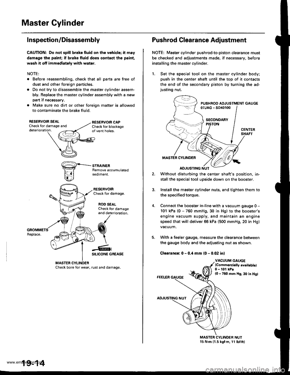
Master Cylinder
I nspection/Disassembly
CAUTION: Do not spill brake fluid onthe vehicle; it may
damsge the paint; il brake fluid does contact th6 paint.
wash it off immodiately with water.
NOTE:
. Before reassembling, check that all parts are free of
dust and other foreign particles.
. Do not try to disassemble the master cylinder assem-
bly. Replace the master cylinder assembly with a new
pan it necessary,
. Make sure no dirt or other foreign matter is allowed
to contaminate the brake fluid.
RESERVOIR SEALCheck for damaoe anddeterioration,
RESERVOIRCheck for damage.
ROD SEALCheck for damageand deterioration.
-€-1SILICONE GREASE
MASTER CYLINOERCheck bore for wear, rust and damage.
19-14
Pushrod Clearance Adjustment
NOTE: Master cylinder pushrod-to-piston clearance must
be checked and adjustments made, if necessary. before
installing the master cylinder.
1. Set the special tool on the master cylinder body;
push in the center shaft until the top ot it contacts
the end of the secondary piston by turning the ad-justing nut.
PUSHROD ADJUSTMENT GAUGE07JAG - SD{o100
SECONDARY
MASTER CYLINDER
ADJUSTING NUT
Without disturbing the center shaft's position, in-
stallthe special tool upside down on the booster.
Install the master cylinder nuts, and tighten them to
the sDecified toroue.
Connect the booster iniine with a vacuum gauge 0 -
101 kPa (0 - 760 mmHg, 30 in Hg) to the booster's
engine vacuum supply, and maintain an engine
speed that will deliver 66 kPa (500 mmH9, 20 in Hg)
vacuum.
With a feeler gauge, measure the clearance between
the gauge body and the adiusting nut as shown.
Clearanco: 0 - 0.4 mm (0 - 0.02 inl
VACUUM GAUGElCommo.cidly 6vailablcl0 - 101 kPtl0 - 760 mm Hg, 30 in Hgl
MASTER CYLINDER NUT15 N.m 11.5 kgt m, 11 lbt.ftl
www.emanualpro.com
Page 939 of 1395
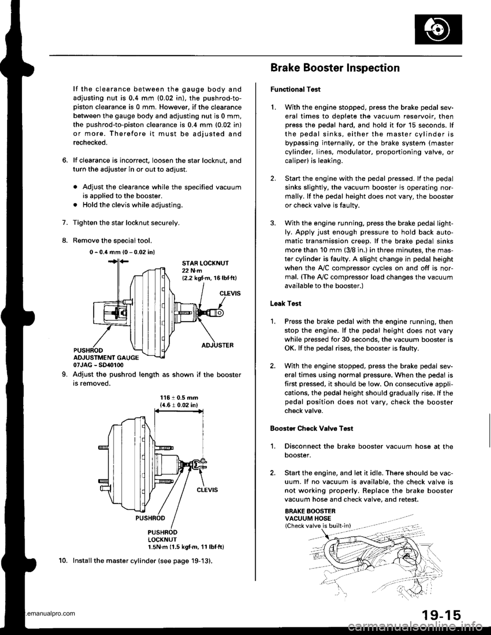
6.
7.
8.
lf the clearance between the gauge body and
adjusting nut is 0.4 mm (0.02 in), the pushrod-to-
piston clearance is 0 mm. However. if the clearance
between the gauge body and adjusting nut is 0 mm,
the pushrod-to-piston clearance is 0.4 mm (0.02 in)
or more. Therefore it must be adjusted and
recheck€d.
lf clearance is incorrect, loosen the star locknut, and
turn the adjuster in or out to adjust.
. Adjust the clearance while the specified vacuum
is applied to the booster.
. Hold the clevis while adjusting.
Tighten the star locknut securely.
Remove the special tool.
0 - 0.4 mm (0 - 0.02 inl
Adjust the pushrod length as shown if the
is removed,
booster
11610.5 mm{4.6 t 0.02 inl
PUSHRODLOCKNUT1.5N.m 11.5 kgf.m. '11 lbtfl)
Install the master cylinder (see page 19-13).
9.
STAR LOCKNUT22 N.m12.2 kgt m. 16 lbtftl
10.
(Check valve is built-in)
Brake Booster Inspection
FunctionalTest
1. With the engine stopped, press the brake pedal sev-
eral times to deplete the vacuum reservoir. thenpress the pedal hard, and hold it for 15 seconds. lf
the pedal sinks, either the master cylinder is
bypassing internally, or the brake system (master
cylinder, lines, modulator, proportioning valve. or
caliper) is leaking.
2. Start the engine with the pedal pressed. lf the pedal
sinks slightly. the vacuum booster is operating nor-
mally. lf the pedal height does not vary, the booster
or check valve is faultv.
3. With the engine running, press the brake pedal light-
ly. Apply just enough pressure to hold back auto-
matic transmission creep. lf the brake pedal sinks
more than 10 mm (3/8 in.) in three minutes, the mas-
ter cylinder is faulty. A slight change in pedal height
when the Ay'C compressor cycles on and off is nor-
mal. (The Ay'C compressor load changes the vacuum
available to the booster.)
Leak Test
1.Press the brake pedal with the engine running, then
stop the engine. lf the pedal height does not vary
while pressed for 30 seconds, the vacuum booster is
OK. lf the pedal rises, the booster is faulty.
With the engine stopped, press the brake pedal sev-
eral times using normal pressure. When the pedal is
first pressed. it should be low, On consecutive appli-
cations, the pedal height should gradually rise. lf thepedal position does not vary. check the booster
check valve.
Boostor Chock Valve Test
1. Disconnect the brake booster vacuum hose at the
booster.
2. Start the engine, and let it idle. There should be vac-
uum. lf no vacuum is available, the check valve is
not working properly. Replace the brake booster
vacuum hose and check valve. and retest.
ERAKE BOOSTERVACUUM HOSE
www.emanualpro.com