Lock HONDA CR-V 1998 RD1-RD3 / 1.G Owners Manual
[x] Cancel search | Manufacturer: HONDA, Model Year: 1998, Model line: CR-V, Model: HONDA CR-V 1998 RD1-RD3 / 1.GPages: 1395, PDF Size: 35.62 MB
Page 452 of 1395
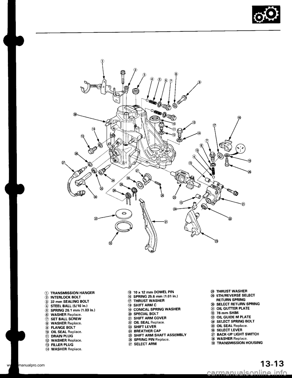
C) TRANSMISSION HANGER
O INTERLOCK BOLT
O 32 mm SEALING BOLT
@ STEEL BALL {5/16 in.)
€) SPRING 26.1 mm {1.03 in.l
@ wasHER Replace.
O sET BALL scREw
@ WASHER Replace.
€) FLANGE BOLT
@ oll SEAL Replace.
@ DRAIN PLUG
@ WASHER Replace.
@ FILLER PLUG
@ WASHER Replace.
(9 10 x 12 mm DOWEL PIN(D SPRING 25.6 mm 11.01 in.l
€' THRUST WASHER
@} SHIFT ARM C(3 CONICAL SPRING WASHER
@ SPECTAL BOLT
8] SHIFT ARM COVER
@ OIL SEAL Replace.
€! SHIFT LEVER
@I BREATHER CAP(2! SHIFT ARM SHAFT ASSEMBLY
@ SPRING PIN Replace.O SELECT ARM
€!} THRUST WASHER
@ sTH/REVERSE SELECTRETURN SPRING
@ SELECT RETURN SPRING
€) OIL GUTTER PLATE
@ 78 mm SHIM
@ OIL GUIOE M PLATE
@ SELECT SPRING BOLT
@ OIL SEAL Replace.
@ SELECT LEVER
O BACK.UP LIGHT SWITCH
@ WASHER Replace.OO TRANSMISSION HOUSING
13-13
www.emanualpro.com
Page 453 of 1395
Transmission Assembly
Disassembly
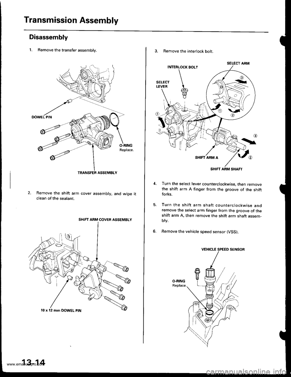
1. Remove the transfer assemblv.
O-RINGReplace.
Remove the shift arm cover assembly, and wiDe itclean of the sealant.
SHIFT ARM COVER ASSEMBLY
10 x 12 mm DOWEL ptN
13-14
3. Remove the interlock bolt.
SELECT ARM
SHIFT ARM SHAFT
Turn the select lever counterclockwise, then removethe shift arm A finger from the groove of the shiftforks.
Turn the shift arm shaft counterclockwise andremove the select arm finger from the groove of theshift arm A. then remove the shift arm shaft assem-blv.
Remove the vehicle speed sensor (VSS).
5.
6.
www.emanualpro.com
Page 456 of 1395
20.
2't.
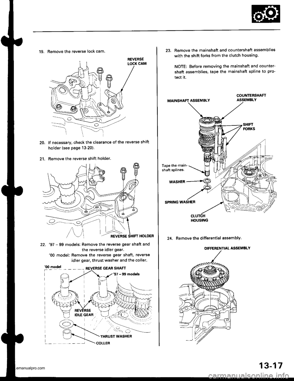
19. Remove the reverse lock cam.
lf necessary, check the clearance of the reverse shift
holder (see page 13-20).
Remove the reverse shift holder.
HOLOER
22. '97 - 99 models: Remove the reverse gear shaft and
the reverse idler gear.'00 model: Remove the reverse gear shaft, reverse
idler gear, thrust washer and the coller.
13-17
23. Remove the mainshaft and countershaft assemblies
with the shift forks from the clutch housing.
NOTE; Before removing the mainshaft and counter-
shaft assemblies, tape the mainshaft spline to pro-
tect it.
ASSEMBLY
Tape the main'
shaft splines.
WASHER
SPRING WASHER
24. Remove the differential asssmbly.
COUNTEBSHAFT
HOUSING
www.emanualpro.com
Page 457 of 1395
Shift Arm Cover/Shift Arm Shaft Assembly
Disassembly/Reassembly
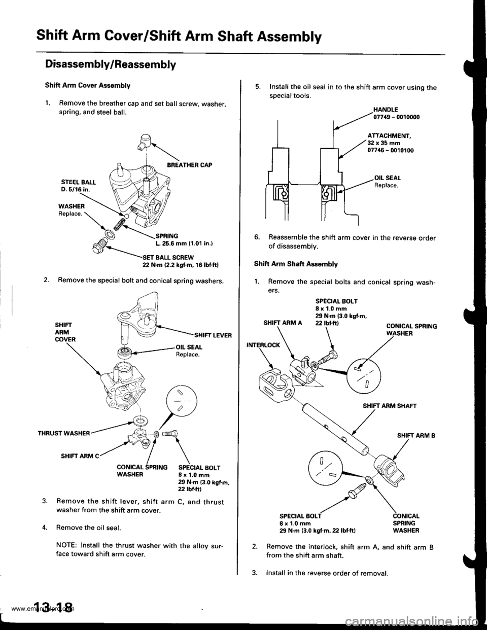
Shift Arm Cover Ass€mbly
1. Remove the breather cap and set ball screw, washer,
spring. and steel ball.
BREATHER CAP
SPRINGL,25.6 mm (1.01 in.l
T BALL SCREW22 N.m 12.2 kgtm, 16lbf.ftl
Remove the special bolt and conical spring washers.
SHIFTARMCOVER
THRUST WASHER
SHIFI ARM C
WASHER 8x1.0mft
SHIFT LEVER
29 N.m 13.0 kg{.m,z2 tbt.ftl
arm C, and thrustRemove the shift lever, shift
washer from the shift arm cover.
Remove the oil seal.
NOTE: lnstall the thrust washer
face toward shift arm cover.
STEEL BALLD. 5/16 in,
13-18
with the alloy sur-
3. Install in the reverse order of removal.
5. Install the oil seal in to the shift arm cover usino thesDecialtools.
HANOLE07749 - 0010000
ATTACHMENT,32x35mm077a6 - 0010100
OIL SEALReplace.
6. Reassemble the shift arm cover in the reve.se order
of disassembly.
Shift Arm Shaft Assembly
1. Remove the special bolts and conical spring wash-
ers.
SPCCIAL BOLT8x1.0mm29 N.m (3.0 kgf.m,SHIFTARMA 22IbI.ftICONICAL SPRING
SHIFT ARM SHAFT
SPECIAL BOLT8x1.0mm29 N.m {3.0 kgf.m, 22 lbtft}
2. Remove the interlock, shift
from the shift arm shaft.
SPRINGWASHER
arm A, and shift arm B
www.emanualpro.com
Page 464 of 1395
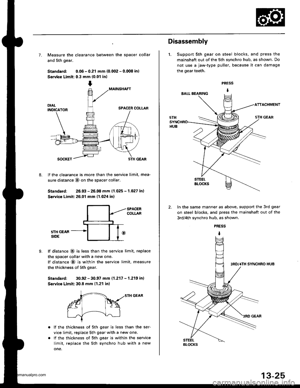
7. Measure the clearance between the spacer collar
and 5th gear.
Standard: 0.06 - 0.21 mm {0.002 - 0.008 in)
Service Limit: 0.3 mm {0.01 in)
MAINSHAFT
SPACER COLLAR
8.
SOCKET5TH GEAR
lf the clearance is more than the service limit, mea-
sure distance @ on the spacer collar
Standard: 26.03 - 26.08 mm 11.025 - 1.027 in)
S€rvico Limit: 26.01 mm (1.024 in)
9.
SPACERCOLLAR
5TH GEARSIDE
lf distance @ is less than the service limit, replace
the spacer collar with a new one.
lf distance @ is within the service limit, measure
the thickness of sth gear.
Standard: 30.92 - 30.97 mm (1.217 - 1.219 in)
Service Limit: 30.8 mm (1.21 in)
r-- ,,srH GEAR
gt Fq
I .J'-----!--\--J-l
lf the thickness of 5th gear is less than the ser-
vice limit, replace 5th gear with a new one.
li the thickness of sth gear is within the service
limit, replace the sth synchro hub with a new
one.
Disassembly
1. Support 5th gear on steel blocks, and press the
mainshaft out of the 5th synchro hub, as shown. Do
not use a jaw-type puller, because it can damage
the gear teeth.
PRESS
I
ACHMENT
In the same manner as above, support the 3rd gear
on steel blocks. and press the mainshaft out of the
3rd/4th svnchro hub, as shown.
PRESS
I
BLOCKS
www.emanualpro.com
Page 466 of 1395
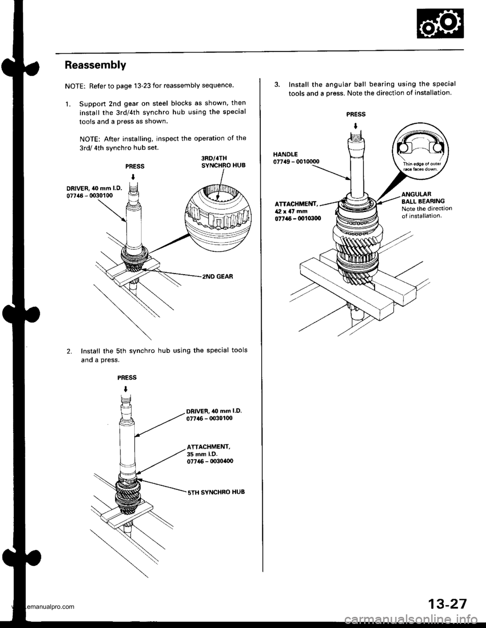
Reassembly
NOTE: Refer to page 13-23 for reassembly sequence.
1. Suppon 2nd gear on steel blocks as shown, then
install the 3rd/4th synchro hub using the special
tools and a press as shown.
NOTE: After installing, inspect the operation of the
3rd/ 4th synchro hub set.
PRESS
I
3RD/4THSYNCHRO HUB
DRIVER, ,l(} mm l.O.
07746 - 0030'�1 00
2.
2NO GEAR
Install the sth synchro hub using the special tools
and a press.
PRESS
I
DRlvER,40 mm l.D.
077{6 - 00301(x)
ATTACHMENT,35 mm l.D.077i16 - lx)3ollx)
sTH SYNCHBO HUB
3. Install the angular ball bearing using the special
tools and a oress. Note the direction of installation.
PRESS
I
077a6 - 0011x100
HANDLE07749 - 0010000
ATTACHMENT,/Vl x a7 mm
BALL BEARINGNote the dirediono{ installation.
13-27
www.emanualpro.com
Page 467 of 1395
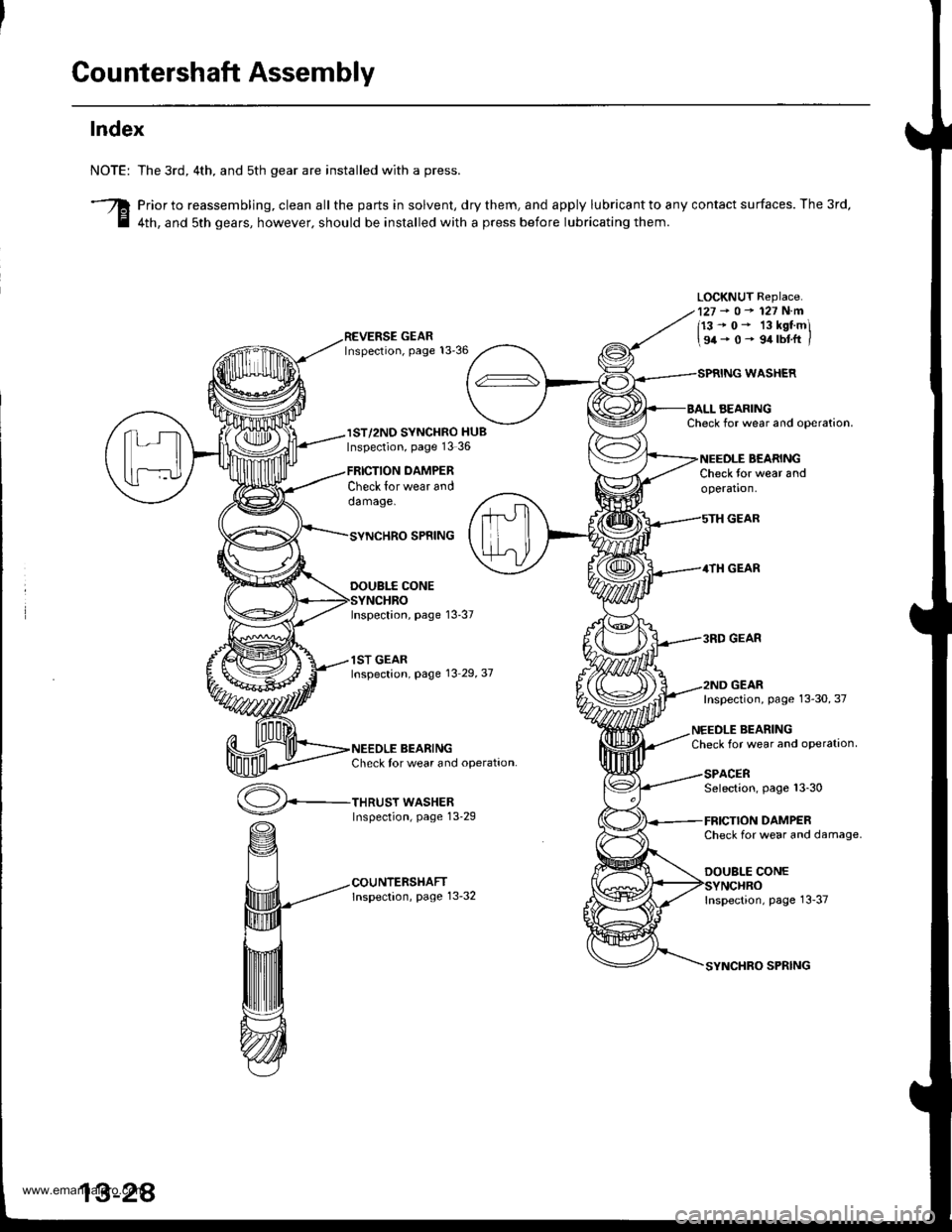
Countershaft Assembly
Index
NOTE:
3
The 3rd, 4th. and sth gear are installed with a press.
Prior to reassembling, clean all the parts in solvent, dry them, and apply lubricant to any contact surfaces. The 3rd,
4th, and sth gears, however. should be installed with a press before lubricating them.
LOCKNUT Replace.127-o-127N.m
113-0- 13kstmi
\94-0- 9.trbtft /
IST/2ND SYNCHRO HUBInspection, page 13 36
Check lor wear anddamage.
THRUST WASHERInspection, page 13-29
DAMPER
WASHER
AEARINGCheck for wear and ooeration.
BEARINGCheck for wear andoperation.
GEAR
4TH GEAR
3RD GEAR
GEAR
SPNING
DOUBI.f CONE
Inspection, page 13-37
1ST GEARInspection, page 13 29,37
BEARINGCheck tor wear and operation.
Inspection, page 13-30, 37
NEEDLE BEARINGCheck for wear and oPeration
SPACERSelection, page 13-30
DAMPERCheck for wear and damage.
DOUBLE CONE
Inspection, page 13-37
SPRING
www.emanualpro.com
Page 470 of 1395
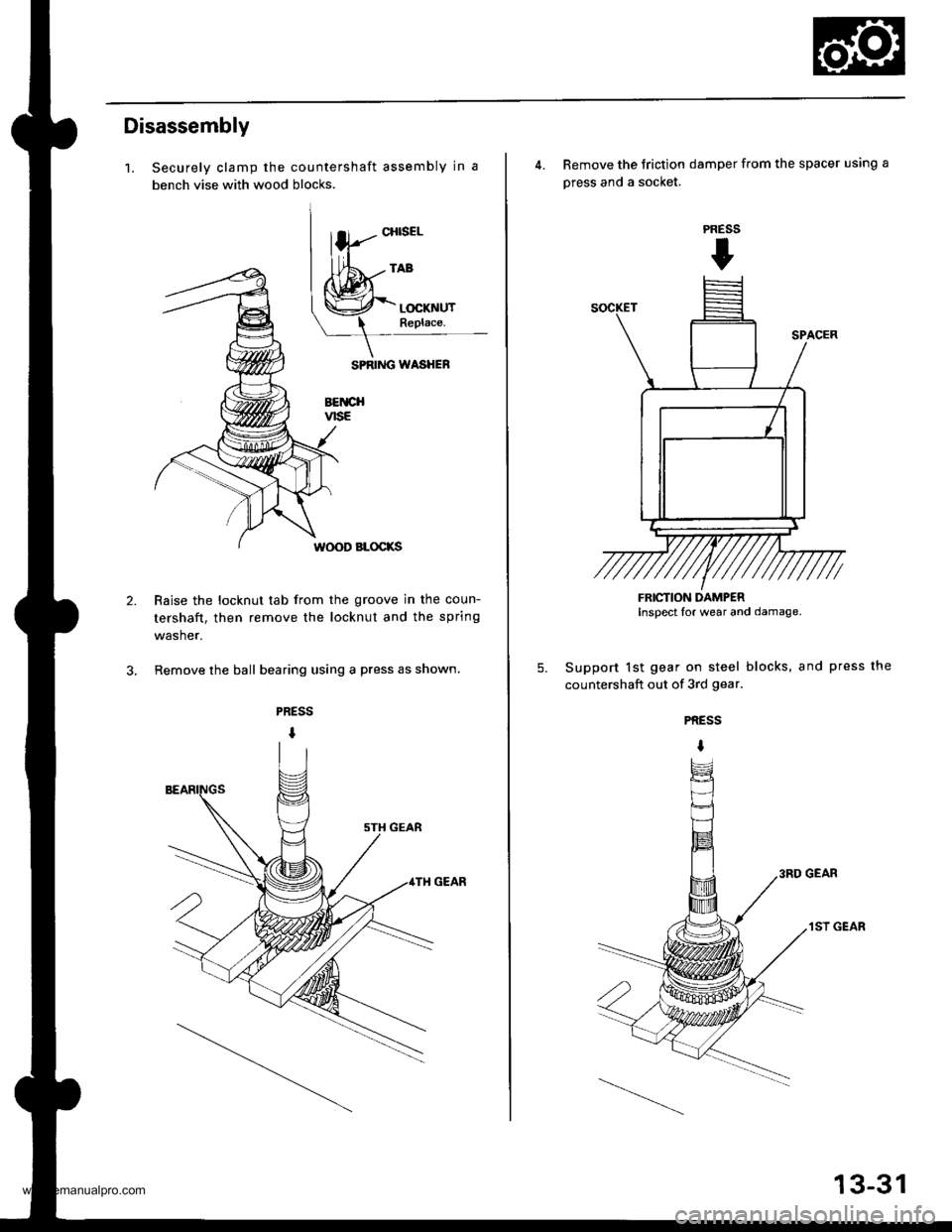
Disassembly
1.
2.
Securely clamp the countershaft assembly in a
bench vise with wood blocks.
SPRIiIG WASHEF
BETICHvtsE
W(X)D BLOCKS
Raise the locknut tab from the groove in the coun-
tershaft, then remove the locknut and the spring
washer.
Remove the ball bearing using a press as shown.
CHISEL
4. Remove the Jriction damper from the spacer using a
press and a socket.
Support lst gear on steel blocks, and press the
countershaft out of 3rd gear.
PRESS
t
5.
PRESS
I
3RD GEAR
1ST GEAR
FRICTION DAMPERInspect lor wear and damage.
13-31
www.emanualpro.com
Page 472 of 1395
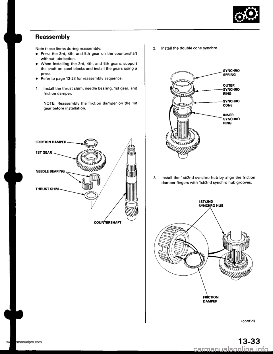
Reassembly
Note these items during reassembly:
. Press the 3rd, 4th, and sth gear on the countershaft
without lubrication.
. When installing the 3rd, 4th. and sth gears, suppon
the shaft on steel blocks and install the gears using a
press.
. Refer to page 13-28 for reassembly sequence.
1. Install the thrust shim, needle bearing, 1st gear, and
friction damper.
NOTE: Reassembly the friction damper on the lst
gear before installation.
rnrcrroru orn,leen ----.-4O)
lST GEAR
NEEDLE BEARING
THRUST SHIM
2. Install the double cone synchro.
3. Install the 1sv2nd synchro hub by align the friction
damper fingers with 1svznd synchro hub grooves.
(cont'd)
OUTER
lST/2ND
13-33
www.emanualpro.com
Page 473 of 1395
Countershaft Assembly
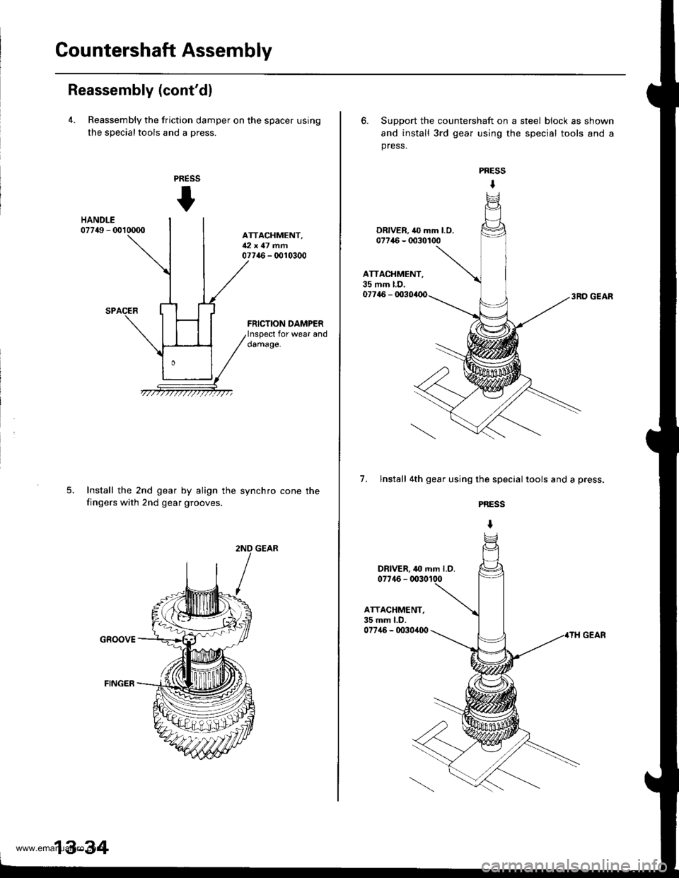
Reassembly (cont'dl
4. Reassembly the friction damper on the spacer using
the sDecialtools and a Dress.
PRESS
t
ATTACHMENT,U2t 47 mfi07716 - 0010300
FRICTION DAMPERInspect for wear anddamage.
Install the 2nd gear by align the
fingers with 2nd gear grooves.
synchro cone the
GROOVE
13-34
6. Support the countershaft on a steel block as shown
and install 3rd gear using the special tools and a
press.
3RO GEAR
7. lnstall 4th gear using the special tools and a press.
PRESS
I
PRESS
t
ATTACHMENT,35 mm LD.07746 - 0030,100
www.emanualpro.com