Rack HONDA CR-V 1998 RD1-RD3 / 1.G Workshop Manual
[x] Cancel search | Manufacturer: HONDA, Model Year: 1998, Model line: CR-V, Model: HONDA CR-V 1998 RD1-RD3 / 1.GPages: 1395, PDF Size: 35.62 MB
Page 1011 of 1395
Glass
Windshield Replacement
CAUTION:
. Put on gloves to protect your hands.
. Use seat covers to avoid damaging any surfaces.
1. To remove the windshield, first remove the:
. Rearview mirror (see page 20-28)
. Sunvisors and holders (see page 20-44l'
. Ceiling light (see section 23)
. Grab handle (see page 20-44)
. Front door trim (see page 20-41)
. Front pillar trim (see page 20-41)
. Windshield wiper arms and cowl cover (see page
20-98)
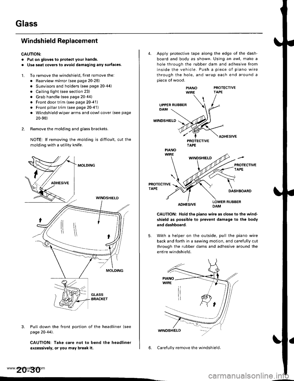
2. Remove the molding and glass brackets.
NOTE: lf removing the molding is difficult, cut the
moldlng with a utility knife.
MOLDING
3. Pull down the front Dortion of the headliner (see
page 20-44).
CAUTION: Take care not to bend the headliner
excessivsly, or you may break it.
WINDSHIELD
20-30
4. Apply protective tape along the edge ot the dash-
board and body as shown. Using an awl, make a
hole through the rubber dam and adhesive from
inside the vehicle. Push a piece of piano wire
through the hole, and wrap each end around a
piece of wood.
PROTECTIVETAPE
WINDSHIELD
ADHESIVE
PIANOWIRE
PROTECTIVETAPE
WINDSHIELO
PROTECTIVETAPEDASHBOARD
ADHESIVELOWER RUBBERDAM
CAUTION: Hold the piano wire as close to the wind-
shield as possible to prevent damage to the body
and dashboard.
5. With a helper on the outside, pull the piano wire
back and fo(h in a sawing motion, and carefully cut
through the rubber dams and adhesive around the
entire windshield.
6. Carefully remove the windshield.
UPPER RUBBER
PIANO
www.emanualpro.com
Page 1012 of 1395
7.
8.
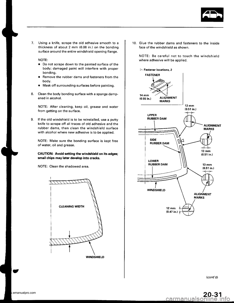
Using a knife, scrape the old adhesive smooth to a
thickness of about 2 mm (0.08 in.) on the bonding
surface around the entire windshield opening flange.
NOTE:
a Do not scrape down to the painted surface of the
body; damaged paint will interfere with proper
bonding.
. Remove the rubber dams and fasteners from the
oooy,
. Mask off surrounding surfaces before painting.
Clean the body bonding surface with a sponge damp-
ened in alcohol.
NOTE: After cleaning, keep oil, grease and water
from getting on the surface.
lf the old windshield is to be reinstalled, use a putty
knjfe to scrape off all traces of old adhesive and the
rubber dams, then clean the windshield surface
with alcohol where new adhesive is to be applied.
NOTE: Make sure the bonding surface is kept free
of water, oil and grease.
CAUTION: Avoid setting tho windshield on its edges;
small chips m8y later devolop into cracks.
NOTE: Clean the shadowed area.
9.
WINDSHIELD
10. Glue the rubber dams and fasteners to the inside
face of the windshield as shown
NOTE: Be careful not to touch the windshield
where adhesive will be applied,
13 mm(0.51 in.)--r-r
>r Fastener locrtions. 2
FASTENEB
\,@,--
w,{,.'>Yl
14 mm -'- \l0.55 in.l ALIGNMENTMARKS
ALIGNMENTMARKS
13 mm(0.51 in.l
13 mm10.51 in.)*ffi
ALIGNMENTMARKS
12 mm(0.47 in.l
(cont'd)
20-31
www.emanualpro.com
Page 1014 of 1395
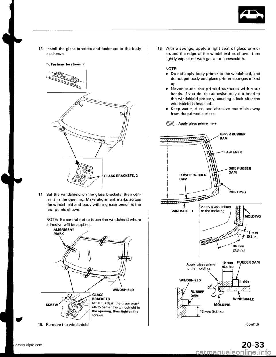
'13. Install the glass brackets and fasteners to the body
as shown.
>: Fastener locations, 2
R-
14. Set the windshield on the glass brackets. then cen
ter it in the opening. Make alignment marks across
the windshield and body with a grease pencil at the
four points shown.
NOTE| Be careful not to touch the windshield where
adhesive will be applied.
ALIGNMENTMABK
WINDSHIELD
GLASSBRACKETSNOTE: Adjust the glass brack-ets to center the windshield inthe opening, then tighten the
15. Remove the windshield.
12 mm 10.5 in.)
16. With a sponge, apply a light coat of glass primer
around the edge of the windshield as shown, then
lightly wipe it off with gauze or cheesecloth.
NOTE:
Do not apply body primer to the windshield, and
do not get body and glass primer sponges mixed
up.
Never touch the primed surfaces with your
hands. lf you do, the adhesive may not bond to
the windshield properly, causing a leak after the
windshield is installed.
. Keep water, dust, and abrasive materials away
from the primed surface.
//fu : Apply glass ptimar hea.
WINDSHIELD
10 mm{0.4 in.}RUBBER DAMApply glass primerto the molding.
(cont'd)
20-33
Apply glass primer
WINDSHIELD
MOLDING
www.emanualpro.com
Page 1026 of 1395
Carpet Replacement
SRS comDonents are located in this area. Review the SRS
component locations, precautions, and procedures in the
SRS section {24) before performing repairs or service.
CAUTION: Put on gloves to protect your hands.
Remove:
. Front seat (see page 20-571
. Rear seat (see page 20 63)
. Kick panel (see page 20-41)
. Center pillar lower trim panel (see page 20 41)
. Front side trim {see page 20-41)
. Lower console cover 1A,/T model, see page 20-49)
. Center console (lM/T model, see page 2o-47)
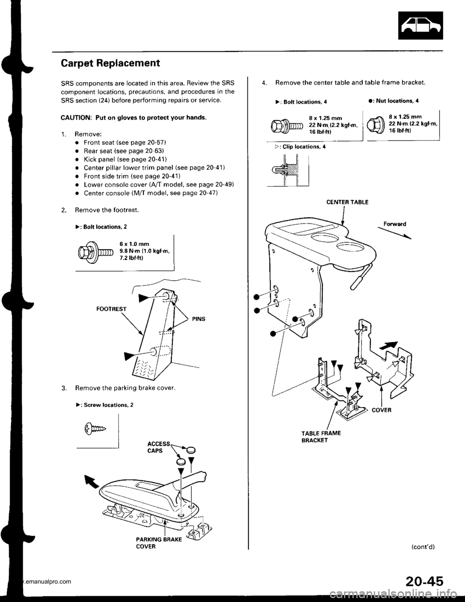
Remove the footrest.
>: Eolt locaiions,2
2.
'1.
6x1.0mm9.8 N.m {1.0 kgf.m,7 .2 tbt.ttt
FOOTREST
3. Remove the parking brake cover.
>: Screw locations,2
6bo" I"l
4. Remove the center table and table frame bracket.
>: Bolt locations, 4a: Nut locations, 4
>: Clip locations, 4
ill
,l
8 x 1.25 mm22N.m l2.2kgl.n,16 tbt ft)
8 x 1.25 mm22 N.m 12.2 kgf.m,16 tbtfrl
Forwaad
TABLE FRAMEBRACKET
{cont'd)
CENTER TABLE
COVER
20-45
www.emanualpro.com
Page 1030 of 1395
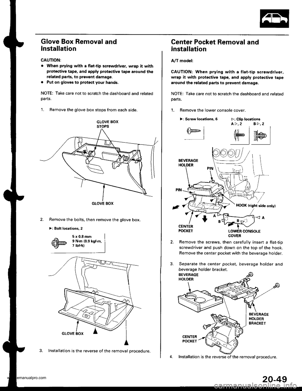
Glove Box Removal and
Installation
CAUTION:
. When prying with a flat-tip 3crewdriver, wrap it withprotective tape, and apply protoqtive tape around ths
related parts, to prgveni damage.
. Put on gloveg to protect your hands.
NOTE: Take care not to scratch the dashboard and related
oarts.
1. Remove the glove box stops from each side.
GLOVE BOXSTOPS
GLOVE BOX
Remove the bolts, then remove the glove box.
>i Bolt locations,2
3. Installation is the reverse of the removal procedure.
20-49
Center Pocket Removal and
Installation
A/T model:
CAUTION: When prying with a tlat-tip screwdriver,
wrap it with protestive tape, and apply protective tape
around the related parts to prevent damage.
NOTE: Take care not to scratch the dashboard and related
oans.
1. Remove the lower console cover.
>: Scrgw locations,6 >: Clip locationsA >,2 B>,2
6F@'' I-l
elsl
Remove the screws, then carefully insert a flat-tip
screwdriver and push down on the top of the hook.
Remove the center pocket with the beverage holder,
Separate the center pocket, beverage holder and
beverage holder bracket.
4. Installation is the reverse of the removal orocedure.
COVER
www.emanualpro.com
Page 1034 of 1395
Dashboard Removal and Installation
SRS components are located in this area. Review the SRS
component locations, precautions, and procedures in the
SRS section {24) before preforming repairs or service.
CAUTION:
. When prying with a flat-tip screwdriver, wrap h withprotective tap€, and apply protective tape around the
related parts to prevgnt damage.
. Put on gloves to prot€ct your hands.
NOTE:
. An assistant is helpful when removing and installing
the dashboard.
. Take care not to scratch the dashboard, bodv and
other related parts.
1.Make sure you have the anti-theft code for the
radio, then write down the frequencies for the
radio's preset buttons.
Disconnect the negative battery cable. and wait at
least three minutes before beginning work.
Removei
a Driver's dashboard lower cover and knee bolster(see page 20-48)
. Glove box (see page 20-49)
. Lower console cover and center pocket (A/T
model, see page 20-49)
. Center console and center upper pocket (M/T
model, see page 20-47)
. Center dashboard lower cover (see page 20-50)
. Power window switch (see page 20-51)
. Driver's side air vent (see page 20-52)
. Driver's side defogger trim (see page 20-52)
Disconnect the driver's airbag connector, and lower
the steering column (see section 17)
NOTE: To prevent damage to the steering column,
wrap it with a shop towel.
2.
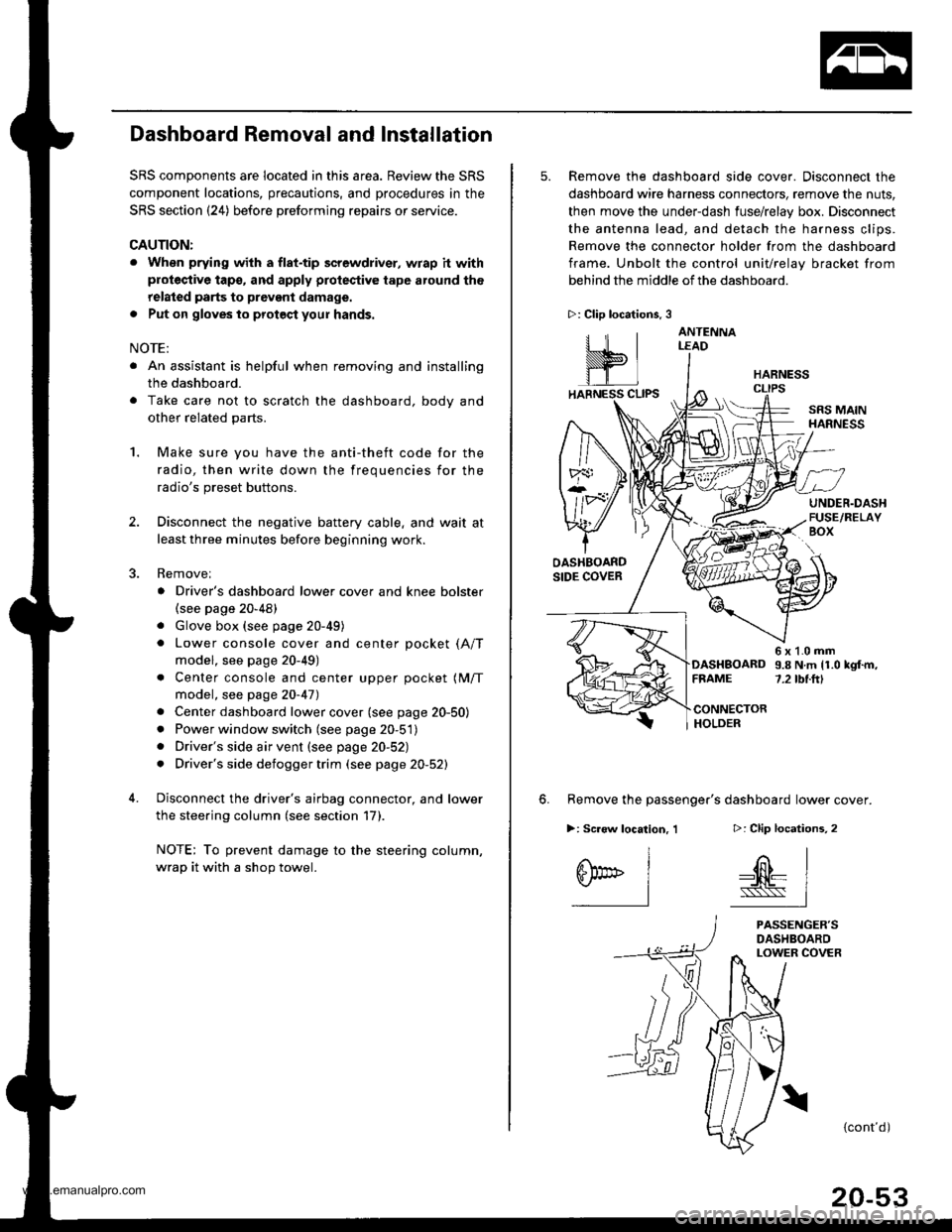
5. Remove the dashboard side cover. Disconnect the
dashboard wire harness connectors, remove the nuts,
then move the under-dash fuse/relay box. Disconnect
the antenna lead, and detach the harness clips.
Remove the connector holder from the dashboard
frame. Unbolt the control unit/relay bracket from
behind the middle of the dashboard.
HARNESS
6. Remove the passenger's dashboard lower cover.
D: Clip locations,
nl
-$t- Issj
I
ANTENNALEAD
>: Clip locations.
rttl
slllll
>: Scr€w location, 1
I
SF:oo I-l
SRS MAINHARNESS
UNDER.DASHFUSE/RELAYBOX
OASHBOARDSIDE COVER
6x1.0mm9.8Nm11.0kgf.m,7.2tbt.ftlDASHBOARDFFAME
CONNECTORHOLDER
PASSENGER'SDASHBOARDLOWER COVER
{cont'd)
www.emanualpro.com
Page 1038 of 1395
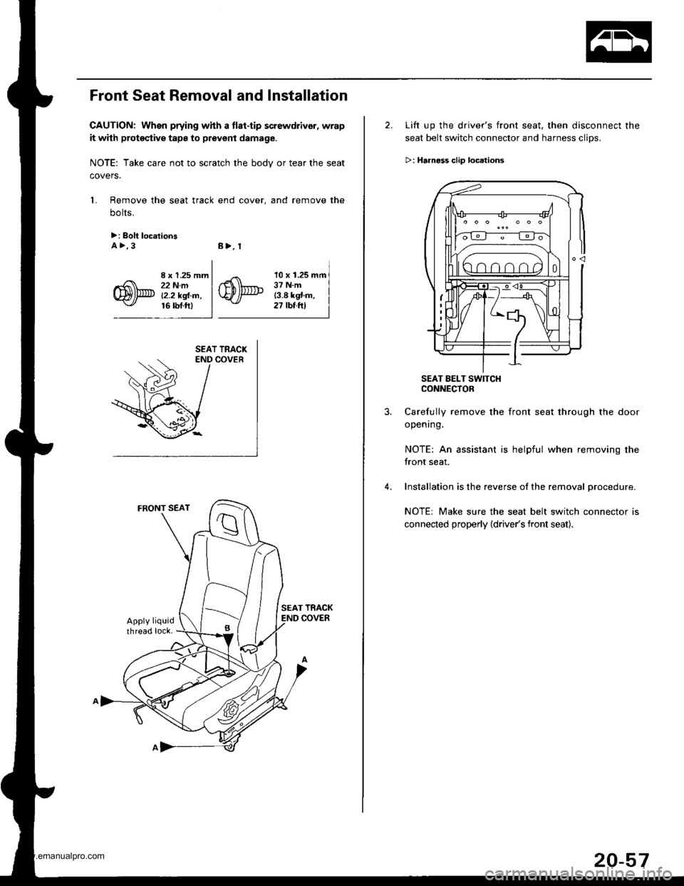
Front Seat Removal and Installation
CAUTION: When prying whh a tlat-tip screwdrivor, wrap
it with proteqtive tape to prevent damage.
NOTE: Take care not to scratch the bodv or tear the seat
covers.
1. Remove the seat track end cover, and remove the
bolts.
>: Bolt loc.tionsA>.3B>, 1
I x 1.25 mm22 N.mi'2.2 kgl.m,16 rbf.ftl
10 x 1.25 mm37 N.m13.8 kgt.m,27 tbt.ftl
2. Lift up the driver's front seat, then disconnect the
seat belt switch connector and harness clips.
>: Hrrnoss clip loc.lions
SEAT BELT SW]TCHCONNECTOR
Carefully remove the front seat through the door
opening.
NOTE: An assistant is helpful when removing the
front seat.
Installation is the reverse of the removal procedure.
NOTE: Make sure the seat belt switch connector is
connected properly (driver's front seat).
20-57
www.emanualpro.com
Page 1048 of 1395
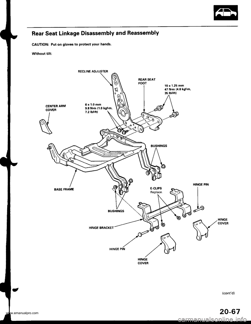
Rear Seat Linkage Disassembly and Reassembly
CAUTION: Put on gloves to protect your hands'
Without tilt:
REAB SEATFOOT
6x1.0mm9.8 N{n 11.0 kgt'm,7.2 tbt ftl
HINGE BRACKET
CENTERCOVER
I
N
HINGE PIN
I
I
b
E-CLIPSReplace.BASE FRAME
(cont'd)
20-67
www.emanualpro.com
Page 1053 of 1395
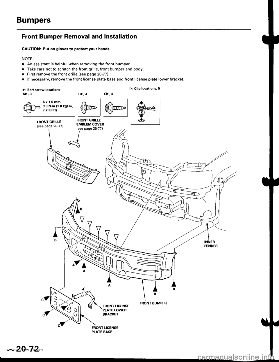
Bumpers
Front Bumper Removal and Installation
CAUTION: Put on gloves to protec,t your hands.
NOTE:
. An assistant is helpful when removing the front bumper.
. Take care not to scratch the front grille, lront bumper and body.
o First remove the front grille (see page 20-77).
. lf necessary, remove the front license plate base and front license plate lower bracket.
B>, 4 C>,4
4 .<\l
S))PF | ffi)m>lv I Y./ |
FRONT GRILLEEMBLEM COVER(see page 20-77)
>: Clip locations,5
.r., I
w€lw
FENDER
IB
FRONT BUMPER
20-72
>: Boli screw locationsA>,3
6x1.0mm9.8 N.m (1.0 kgf.m,7.2 tbt t0
FRONT GRILLE(see page 20-77)
tx -
\{_:
www.emanualpro.com
Page 1145 of 1395
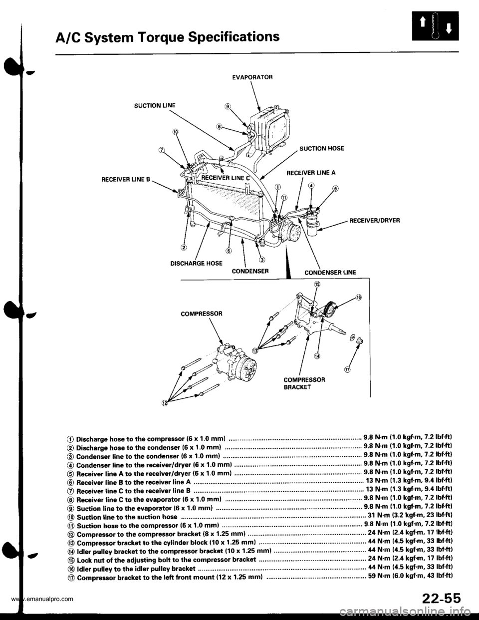
A/C System Torque Specifications
EVAPORATOR
SUCTION LINE
SUCTION HOSE
RECEIVER LINE ARECEIVEN LINE B
RECEIVER/ORYER
O Discharge hos€ to the compressor {6 x 1.0 mml.... 9.8 N.m 11.0 kgrf.m.7.2lbtftl
@ Condenser line to the condenser (6 x 1.0 mm)
@ Condensor line to the receiver/dryer {6 x 1.0 mm) ........9.8 N.m {1.0 kgf.m, 7.2 lbt.ft)
O Receiver line A to the receivor/dryer (6 x 1.0 mm) ...... ....................... 9.8 N.m {1.0 kgf.m.7.2 lbf.ft}
@ Receiver line B to th€ receive. line A
O R€ceiver tine C to the receivor line B
@ Recoiver line C to the evaporator (6 x 1'0 mml9.8 N'm (1.0 kgf.m,7.2lbtftl
O Sustion line to the evaporatot 16 x 1.0 mml
@ Sustion line to the suction hose...... 31 N.m (3.2 kgl.m, 23 lbf.ft)
@ Sucion hose to the qompressor (6 x 1.0 mm) .....'...' 9 8 N'm (1 0 kgt'm, 7'2 lbf'ftI
@ Compressor to the compressor bracket {8 x 1.25 mm) ... 24 N.m l2.il kgf'm, 17 lbf'ft}
@ Compressor bracket to the cylindsr block (10 x 1.25 mm) ................ ......... il,t N'm (4.5 kgt'm, 33 lbf'ft)
@ ldler pulley bracket to the compressor bracket (10 x 1.25 mm)..................... ,14 N.m (/r.5 kgf'm, 33 lbf'ft)
@ Lock nut of the sdiusting boh to the compressor bracket ......................... 24 N'm (2./t kgt'm, 17 lbf'ft)
@|d|erpu||eytotheid|orpu||eybracket.....'..........................'....\
.'.....'........'....44N.m(4.5kg''m'33|bf.f)
@ compressor bracket to the left front mount (12 x 1.25 mml ................... ............................ 59 N'm (6.0 kgt'm, /l:| lbf'ft1
22-55
www.emanualpro.com