HONDA CR-V 1998 RD1-RD3 / 1.G Workshop Manual
[x] Cancel search | Manufacturer: HONDA, Model Year: 1998, Model line: CR-V, Model: HONDA CR-V 1998 RD1-RD3 / 1.GPages: 1395, PDF Size: 35.62 MB
Page 141 of 1395
Valve Seats
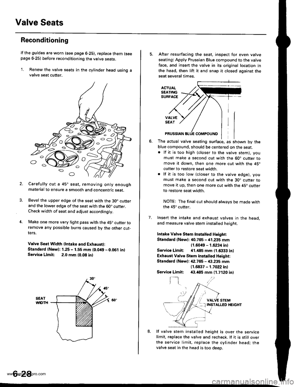
Reconditioning
lf the guides are worn (see page 6-25), replace them (seepage e25) before reconditioning the valve seats.
1. Renew the valve seats in the cylinder head using avalve seat cutter.
Carefully cut a 45o seat, removing only enoughmaterialto ensure a smooth and concentric seat.
Bevel the upper edge of the seat with the 30. cutterand the lower edge of the seat with the 60" cutter.Check width of seat and adjust acco.dingly.
Make one more very light pass with the 45o cutter toremove any possible burrs caused bv the other cut-ters.
Valve Seat Width (lntake and Exhaust):
Standard {N.w}: 1.25 - 1.55 mm (0.049 - 0.051 in)Servica Limit: 2.0 mm (0.08 in)
o
o
5. After resurfacing the seat, inspect for even valve
seating: Apply Prussian Blue compound to the valve
face, and insert the valve in its original location in
the head, then lift it and snap it closed against the
seat several times.
ACTUALSEATINGSURFACE
VALVESEAT
7.
PRUSSIAN
The actual valve seating surface, as shown by the
blue compound, should be centered on the seat.. lf it is too high (closer to the valve stem), you
must make a second cut with the 60" cutter tomove it down, then one more cut with the 45"
cutter to restore seat width.
. lf it is too low (closer to the valve edge), you
must make a second cut with the 30. cutter tomove it up, then one more cut with the 45. cutter
to restore seat width.
NOTE: The final cut should alwavs be made withthe 45" cutter,
Insert the intake and exhaust valves in the head,
and measure valve stem installed heioht.
Intake Vslve Siem Instslted Height:
Standard {Newl: it0.765 - 41.235 mm
11.6049 - 1.6234 inl
Sarvico Limit: itl.il85 mm (1.6333 in)
Exhaust Valve Stem Installed H6ight:
Standard {New}: 42.755 - €.235 mm
11 .61137 - 1 .7022 inl/(|.,185 mm (1.7120 in)
VALVE STEMINSTALLED HEIGHT
8. lf valve stem installed height is over the servicelimit. replace the valve and recheck. lf it is still overthe service limit. replace the cylinder head; thevalve seat in the head is too deeo.
Servico Limit:
f-]
6-28
www.emanualpro.com
Page 142 of 1395
Valves, Valve Springs and Valve Seals
lnstallation
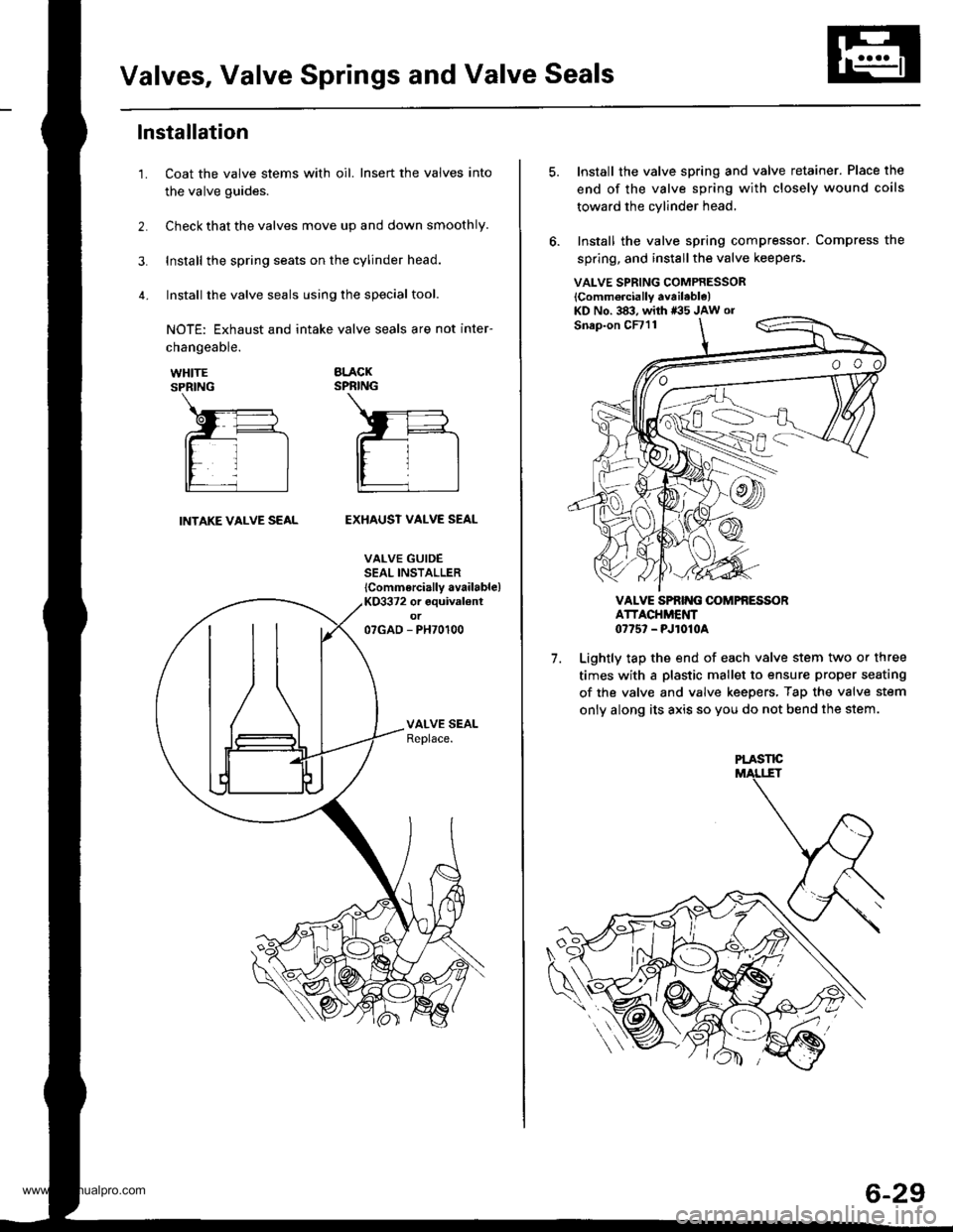
Coat the valve stems with oil. Insert the valves into
the valve guides.
Check that the valves move up and down smoothly.
Install the spring seats on the cylinder head.
Install the valve seals using the special tool.
NOTE: Exhaust and intake valve seals are not inter-
1.
changeable.
WHITESPRING
BLACKSPRING
INTAKE VALVE SEALEXHAUST VALVE SEAL
VALVE GUIDESEAL INSTALLER
lCommercially available)KO3372 or equival€ntot07GAD - PH70100
VALVE SPRING COMPRESSOR
lComm6rcially available)KD No. 383, with *35 JAw or
7.
Install the valve spring and valve retainer. Place the
end of the valve spring with closely wound coils
toward the cylinder head,
Install the valve spring compressor. Compress the
spring, and install the valve keepers.
VALVE SPRIT{G OOMPfi ESSORATTACHMENT0775' - PJ1010A
Lightly tap the end of each valve stem two or three
times with a plastic mallet to ensure proper seating
of the valve and valve keepers, Tap the valve stem
only along its axis so you do not bend the stem.
PLASTE
6-29
www.emanualpro.com
Page 143 of 1395
Cylinder Head
Installation
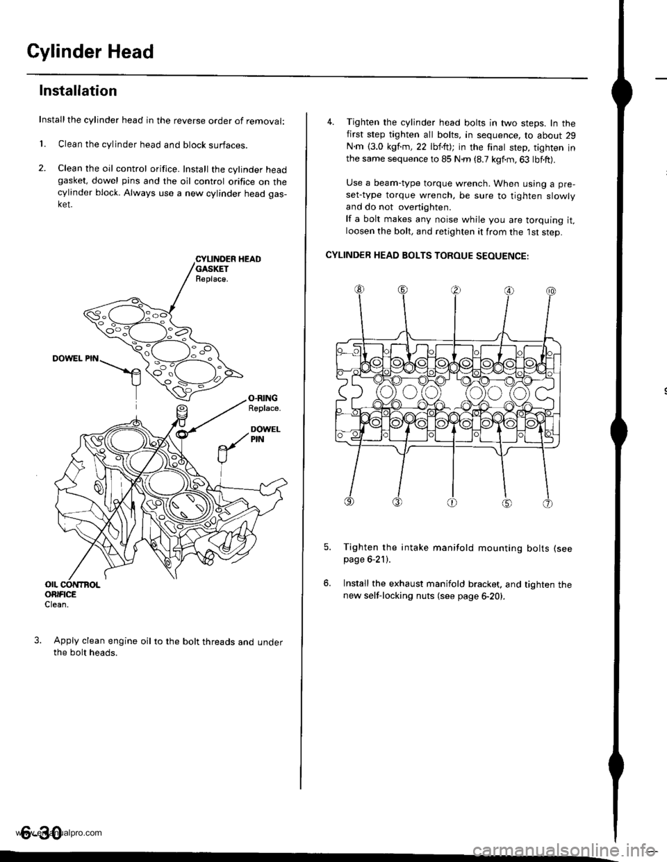
Installthe cylinder head in the reverse order of removal:
1. Clean the cylinder head and block surfaces.
2. Clean the oil control orifice. Install the cylinder headgasket, dowel pins and the oil control orifice on thecylinder block. Always use a new cylinder head gas-ket.
CYLII{DER HEADGASKETR€place.
DOWEL PIN
O.RINGRoplace.
DOWELPIN
OIL CONTBOLORIFICEClean.
Apply clean engine oil to the bolt threads and underthe bolt heads.
4. Tighten the cylinder head bolts in two steps. In thefirst step tighten all bolts, in sequence, to about 29
N.m {3.0 kgf.m,22 lbf.ft); in the finat step, tighten inthe same sequence to 85 N.m (8.7 kgf.m,63 lbf.ft).
Use a beam-type torque wrench. When using a pre-
set-type torque wrench, be sure to tighten slowly
and do not overtighten.
lf a bolt makes any noise while you are torquing it,loosen the bolt, and retighten it from the 1st step.
CYLINDER HEAD BOLTS TOROUE SEOUENCE:
Tighten the intake manifold mounting bolts (see
page 6-21).
Install the exhaust manifold bracket. and tighten thenew self-locking nuts (see page 6-20).
6-30
www.emanualpro.com
Page 144 of 1395
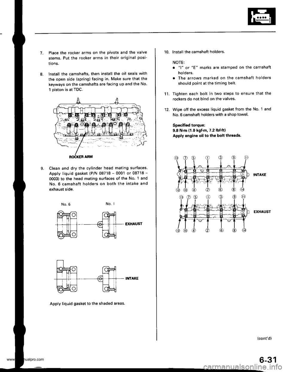
7.Place the rocker arms on the pivots and the valve
stems. Put the rocker arms in their original posi-
lrons.
lnstall the camshafts, then install the oil seals with
the open side (spring) facing in. Make sure that the
keyways on the camshafts are facing up and the No.
1 piston is at TDC.
Clean and dry the cylinder head mating surfaces.
Apply liquid gasket (P/N 08718 - 0001 or 08718 -
0OO3) to the head mating surfaces of the No. 1 and
No. 6 camshaft holders on both the intake and
exhaust side.
L
No. I
EXHAUST
II{TAKE
Apply liquid gasket to th€ shaded areas.
't't,
'10. lnstall the camshaft holders.
NOTE:
o "1" or "E' marks are stamped on the camshaft
holders.
. The arrows marked on the camshaft holders
should point at the timing belt.
Tighten each bolt in two steps to ensure that the
rockers do not bind on the valves.
Wipe off the excess liquid gasket from the No. 1 and
No. 6 camshaft holders with a shop towel,
Specified torque:
9.8 N.m (1.0 kgf.m, 7.2 lbf.ft)
Apply engine oil to the bolt ihreads.
I?,ITAKE
EXHAUST
(cont'd)
6-31
www.emanualpro.com
Page 145 of 1395

Cylinder Head
Installation (cont'dl
'13. Align the marks on the cylinder head plug to thecylinder head upper surface, then install the cylin
der head plug in the end of the cylinder head.
CYLINOER HEADPLUGReplace.
lnstallthe back cover.
To set the camshafts at TDC position for the No. lpiston, align the holes in the camshafts with theholes in the No. l camshaft holders and insert 5.0mm pin punches in the holes. Install the keys into
the camshaft grooves.
37 N m (3.8 *gl.m, 27 lbt.tr)
9.8 N.m (1.0 kgtm,7.2|hrftl
Push the camshaft pulleys onto the camshafts. thentighten the retaining bolts to the torque specified.
6-32
14.
KEYS
I x 1.25 mm
6x1.0mm
Install the timing belt (see page 6-1 1).
Adjust the valve clearance (see page 6-3).
Thoroughly clean the head cover gasket and thegroove.
lnstall the head cover gasket in the groove of thecylinder head cover. Seat the head cover gasket in
the recesses for the camshaft first, then work it into
the groove around the outside edges. Make sure thehead cover gasket is seated securely in the corners
of the recesses with no gap.
17.
'18.
19.
www.emanualpro.com
Page 146 of 1395
21.
22.
Check that the mating surfaces are clean and dry.
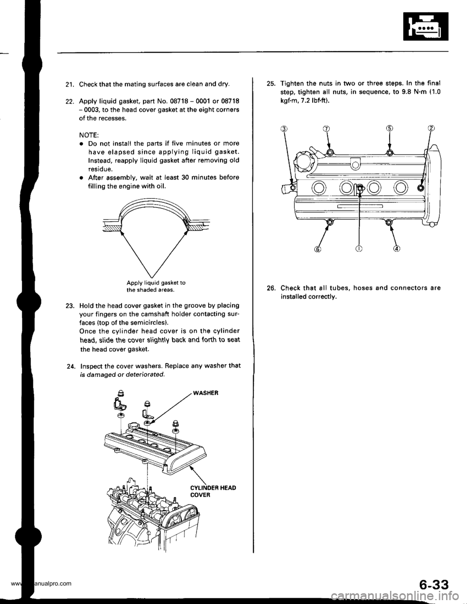
Apply liquid gasket, part No. 08718 - 0001 or 08718- 0003, to the head cover gasket at the eight corners
of the recesses.
NOTE:
. Do not install the parts if five minutes or more
have elapsed since applying liquid gasket.
Instead, reapply liquid gasket after removing old
residue.
. After assembly. wait at least 30 minutes before
filling the engine with oil.
Apply liquid gasket tothe shaded areas.
Hold the head cover gasket in the groove by placing
your fingers on the camshaft holder contacting sur-
faces (top of the semicirclesl.
Once the cylinder head cover is on the cylinder
head, slide the cover slightly back and forth to seat
the head cover gasket.
Inspect the cover washers. Replace any washer that
is damaged or dete(iorated.
23.
24.
25. Tighten the nuts in tvvo or three steps. In the final
step, tighten all nuts, in sequence. to 9.8 N.m (1.0
kgf.m, 7.2 lbf.ft).
Check that all tubes, hoses and connectors are
installed correctly.
26.
6-33
www.emanualpro.com
Page 147 of 1395
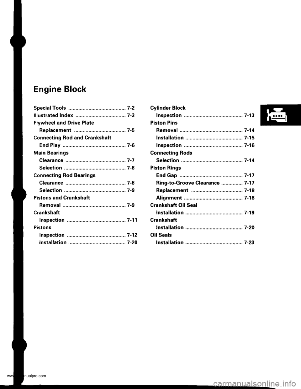
Engine Block
Speciaf Tools .............7-2
lllustrated lndex ................................... 7-3
Flywheel and Drive Plate
Replacement ..,.,....7-5
Connecting Rod and Grankshaft
End Play .................7-6
Main Bearings
Cfearance ...............7 -7
Selection ................7-8
Connecting Rod Bearings
Clearance ...............7-8
Selection ................7-9
Pistons and Crankshaft
Removal .................7-9
Crankshaft
Inspection .............. 7-11
Pistons
fnspection ..............7-12
fnstaflation .............7-20
Cylinder Block
Inspection ..............7-13
Piston Pins
Removal ..,.......,,..... 7-14
Installation ............. 7-15
Inspection .............. 7-16
Connecting Rods
Selection ................7 -14
Piston Rings
End Gap .................7 -17
Ring-to-Groove Clearance ............... 7 -17
Replacement .........7-18
Alignment .............. 7-18
Crankshaft Oil Seal
lnstallation ............. 7-19
Crankshaft
lnstalfation .............7-20
Oil Seals
fnstalfation ....,..,.....7-23
www.emanualpro.com
Page 148 of 1395
Special Toolstl
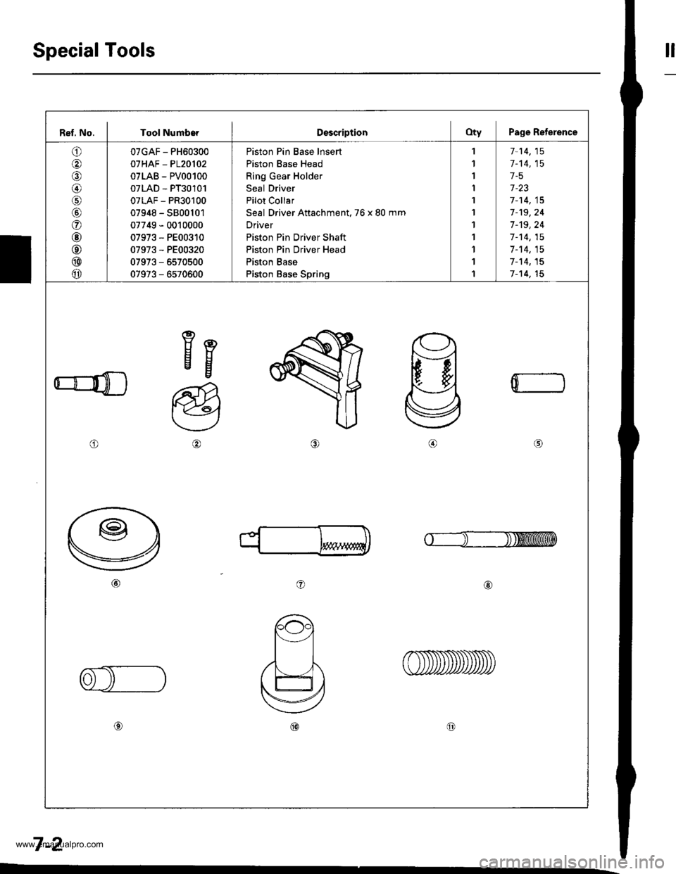
Ref, No. I Tool NumborDescriptionOty Page Reterence
o
@
@/6
@
o
@
@
@
@
07GAF - PH60300
07HAF - P120102
07LAB - PV00100
07LAD - PT30101
07LAF - PR30100
07948 - S800101
07749 - 0010000
07973 - PE00310
07973 - PE00320
07973 - 6570500
07973 - 6570600
Piston Pin Base lnsert
Piston Base Head
Ring Gear Holder
Seal Driver
Pilot Collar
Seal Driver Attachment. 76 x 80 mm
Driver
Piston Pin Driver Shaft
Piston Pin Driver Head
Piston Base
Piston Base Spring
,l
1
I
I
1
1
1
1
1
1
1
7-14,15
1-'t4,15
1-5
1-23
7-14,15
7-'t9,24
7 -'t9, 24
1-14,15
7-14,15
7-'t4,15
7-14,15
eEEg
o
a@
0
o@
7-2
www.emanualpro.com
Page 149 of 1395
lllustrated lndex
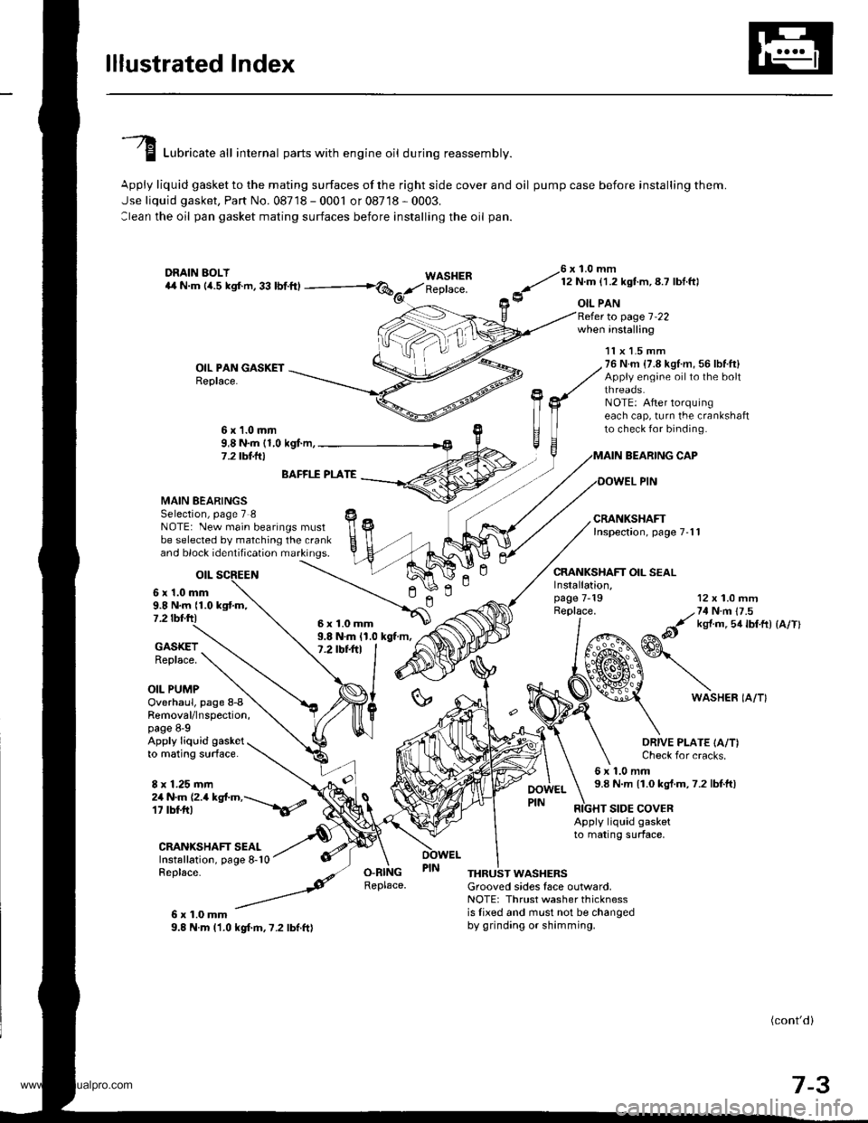
I Luori""t" "tl internal parts with engine oil during reassembly.
Apply liquid gasket to the mating surfaces of the right side cover and oil pump case before installing them.
Jse liquid gasket, Part No. 08718 - 0001 or 08718 - 0003.
:lean the oil pan gasket mating surfaces before installing the oil pan.
WASHERReplace.
76 x 1.0 mm
y' t:n- l.zxstm, 8.7 lbl ftl
9 oIL PAN
OIL PAN GASKETReplace.
to page 1-22when installing
BEARING CAP
OOWEL PIN
CRANKSHAFT OIL SEAL
11x 1.5 mm76 N.m {7.8 kgl.m, 56 lbf.ft}Appiy engine oilto the boltthreaos.NOTE: After lorquingeach cap, turn the crankshaftto check for binding.6x1.0mm9,8 N.m (1,0 kgf.m,7 .2 tbt.lrl
n
MAIN BEARINGSSelection, page 7 8NOTE: New main bearings mustbe selected by matching the crankand block identification markings.
otL
6 x'1.0 mm9.8 N.m {1.0 kgtm,7.2 tbf.ftl
BAFFI.f PLATE
9.8 N.m 11.0 kgt m,7.2 tbt+tl
12 x 1.0 mm
/,71N n 17 .5
&it ks{ m 5a lbtft) {a/Tl
GASKETReplace.
OIL PUMP
Installation,page 7-19Replace.
ln
6WASHER IA/T}Overhaul, page 8-8Removal/lnspection,page 8-9Apply liquid gasketto mating surface.
8 x 1.25 mm
ORIVE PLATE IA/T)Check for cracks.
6x1.0mm9.8 N.m 11.0 kgt.m,7.2 lbtft)2a N.m (2.a kgt.m,---\6/
CRANIGHAFT SEALInstallation, page 8-10Replace-
6x1.0mm9.8 N.m l'1.0 kgf.m,7.2 lbf.ft)
RIGHT SIDE COVERApply liquid gasketto mating surface,
O.RINGReplace.THRUST WASHERSGrooved sides face outlvard,NOTE: Thrust washer thicknessis lixed and must not be changedby grinding or shimming.
(cont'd)
7-3
6x1.0mm
www.emanualpro.com
Page 150 of 1395
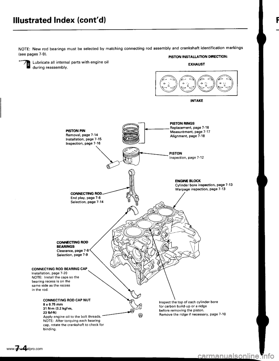
lllustrated Index (cont'd)
NOTE: New rod bearings
(see pages 7-91.
must be selected by matching connecting rod assembly and crankshaft identification markings
PISTON INSTALLANON DIRECTION:
Lubricate all internal parts with engine oil
during reassembly.EXHAUST
INTAKE
PISTON RINGSReplacement. page 7-18Measurdment, page 7-17Alignm€nt, page 7-18
PISTONInspection, page 7-12
l1\AAtr\
\9q9Q9e/
PISTON PINRemoval, page 7-14
Installation, page 7-15Inspection. page 7-16
ENGINC BLOCKCylinder bore inspection. pago 7-13
Warpage inspoction, Page 7-'13
CONNECTING ROD BEARING CAPlnstallation, page 7-20NOTE: Install the caps so thebearing recess is on thesame side as the recessin the rod.
CONNECTING ROD CAP8 x 0.75 mm31 N.m {3.2 kgl.m.23 tbf.ftl
CONNECTING
COiINECI'ING RODBEARINGSClearance, page 7-8
Solection. page 7-9
NUT
End play, page 7-6Selection, page 7-14
Inspect the top ot each cylinder borefor carbon build up or a ridgebelore removing the piston.
Remove the ridge if necessary, page 7-10Apply engine oil to the bolt threads.NOTE: After torquing each bearingcap, rotate the crankshaft to check forbinding.
7-4
www.emanualpro.com