5 speed HONDA CR-V 1998 RD1-RD3 / 1.G Workshop Manual
[x] Cancel search | Manufacturer: HONDA, Model Year: 1998, Model line: CR-V, Model: HONDA CR-V 1998 RD1-RD3 / 1.GPages: 1395, PDF Size: 35.62 MB
Page 960 of 1395
Kickback'1. The motor operates when the ABS is functioning. and the fluid in the reservoir is forced out to the master cylinder,
causing kickback at the brake pedal.
2. The ABS control unit operates the solenoid valve when the brake pedal is released after the initial diagnosis You may
hear the solenoid valve operate at this time, but it is normal
Pumo Motol
1. The pump motor operates when the ABS is functioning
2. The ABS control unit checks the pump motor operation during acceleration. You may hear the motor operate at this
time, but it is normal.
Brake Fluid Replacement/Ail Bleeding
L Brake fluid replacement and air bleeding procedures are the same as for vehicles without ABS To ease bleeding, start
with the front wheels.
Troubleshooting
1. The troubleshooting flowchart procedures assume that the cause of the problem is still present and the ABS indicator
is still on. Following the flowchart when the ABS indicator does not come on can result in incorrect diagnosis.
2. Ouestion the customer about the conditions when the problem occurred, and try to reproduce the same conditions
for troubleshooting.
Self-diagnosis is made at various times such as the initial diagnosis, except ABS control, during ABS control, during
acceleration, during the specified vehicle speed, etc. Therefore, the symptom canngt be checked unless the check
conditions match with the problem conditjons
3. When the ABS jndicator does not come on during the test-drive. but troubleshooting is performed based on the DTC,
check lor loose connectors, poor contact of the terminals, etc., before you start troubleshooting.
4. After troubleshooting, erase the DTC and test-drive the vehicle. Be sure the ABS indicator does not come on.
5. The connector illustratjons show the female terminals with a single outline and the male terminals with a double out-
l ne.
ABS Function Test
To simulate ABS operation and activate the solenoid valves and pump, use the Honda PGM Tester.
Connect the PGM Tester to the 16P Data Link Connector (DLC). When the System Select menu is displayed, select the ABS
Test Mode menu, and follow the tester's prompts.
19-37
www.emanualpro.com
Page 968 of 1395
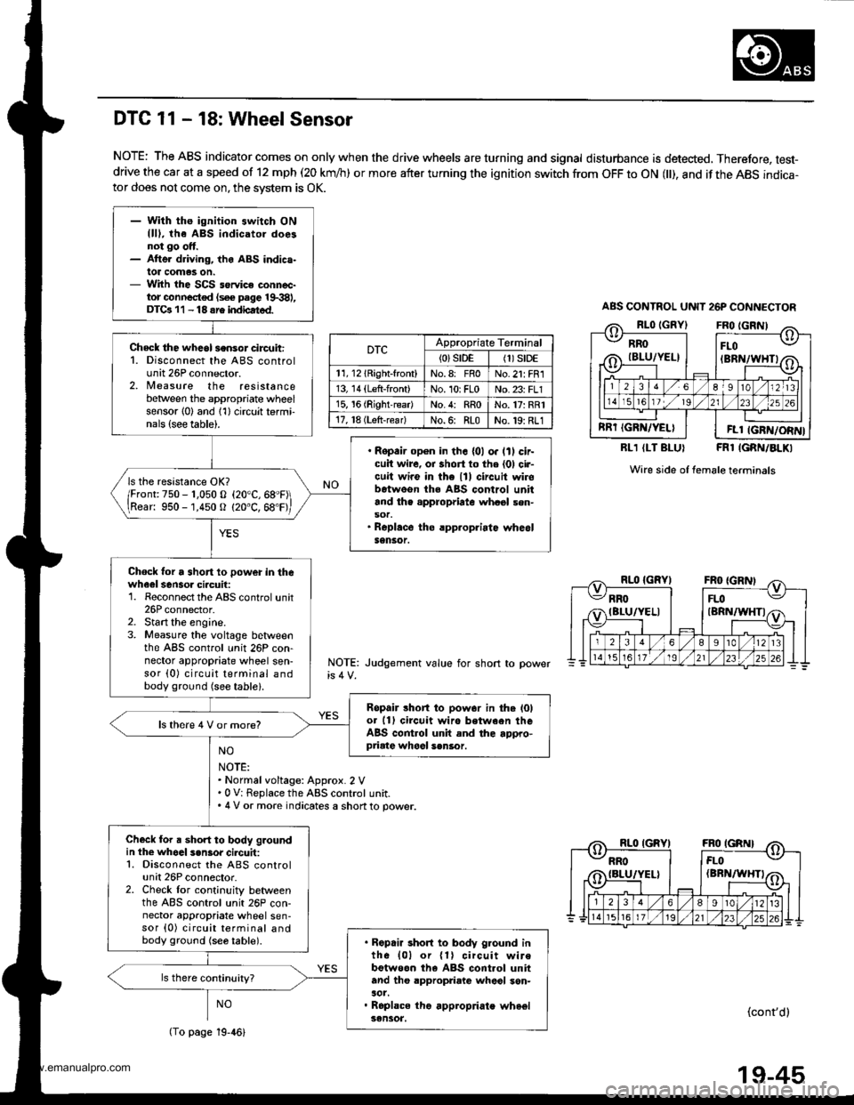
- With ths ignition switch ONllll, the ABS indicatol doesnot go ott.- Atte. driving, the ABS indica-lot comas on.- With the SCS service connec-tor connocted (s€€ page 19.381,DTGr 11 - 18 sre indbated.
Check the whcol sensor circuit:1. Disconnect the ABS controlunit 26P connector.2, Nleasure the resistancebetween the appropriate wheelsensor l0) and 1'l) circuit termi-nals {see table).
. Ropair op€n in th. {01 o. lll cir-cuit wire, oa short to the (01 cir-cuit wire in the lll circuit wirobetweon the ABS control unitand th. appropriate whasl sen-sot.. Roplace the rpp.opriatc whe6lSensor.
ls the resistance OK?
/Fronr:750 - r,050 o (20"C,68"F\
\Rear: 950 -'1,450 O (20"C, 68'F,
Chock lor a short 10 power in thewheel sensoa ciacuil:1. Reconnect the ABS control unit26P connector.2. Start the engine.3. Measure the voltage betlveenthe ABS control unit 26P con-nector appropriate wheel sen-sor (0) circuit terminal andbody ground (see table).
Ropair lhort to pow.r in the l0lot 11) circuit wiro between theABS control unit and the appro-priate whool sen6or.
ls there 4 V or more?
Check for a short to body groundin the whoal s.n3or cilcuit:1. Disconnect the ABS controlunit 26P connector.2. Check lor cont;nuity betweenthe ABS control unit 26P con-nector appropriate wheel sen-sor {0) circuit terminal andbody ground {se6 table).. Ropair short to body g.ound inth6 {01 or {1} circuit wirebotweon th6 ABS cont.ol unitand tho appropriato wheol son-aot.. Roplace tho appropriate wheelsensot.
DTC 11 - 18: Wheel Sensor
NOTE: The ABS indicator comes on only when the drive wheels are turning and signal disturbance is detected, Therefore, test-drive the car at a speed of 12 mph (20 km/h) or more after turning the ignition switch from OFF to ON l), and if the ABS indica-tor does not come on, the svstem is OK.
RLl (LT BLUI FRl IGRN/BLKI
Wire side of female terminals
NOTE: Judgement value for short
NO
NOTE:. Normalvoltage: Approx. 2 V.0 V: Replace the ABS control unit.. 4 V or more indicates a shon to power.
NO(cont'dl
ABS CONTNOL UNIT 26P CONNECTOR
RROIBLU/YEL}
RRT IGRN/YELI
FLO(BRN/WHTI
FLl IGFN/ORN}
DTCAppropriate Terminal
{0}srDE(1)S|DE
11, l2lRight-front)No.8: FnoNo.21: FR1
13, 14 (Left-front)No. 10rFLoNo. 23: FLl
15, 16 (RightreadNo.4: RRoNo.17: RR1
17, l8 (Lsft-rear)No.6: RLoNo.19: RL1
(To page 19-46)
19-45
www.emanualpro.com
Page 1104 of 1395
Troubleshooting
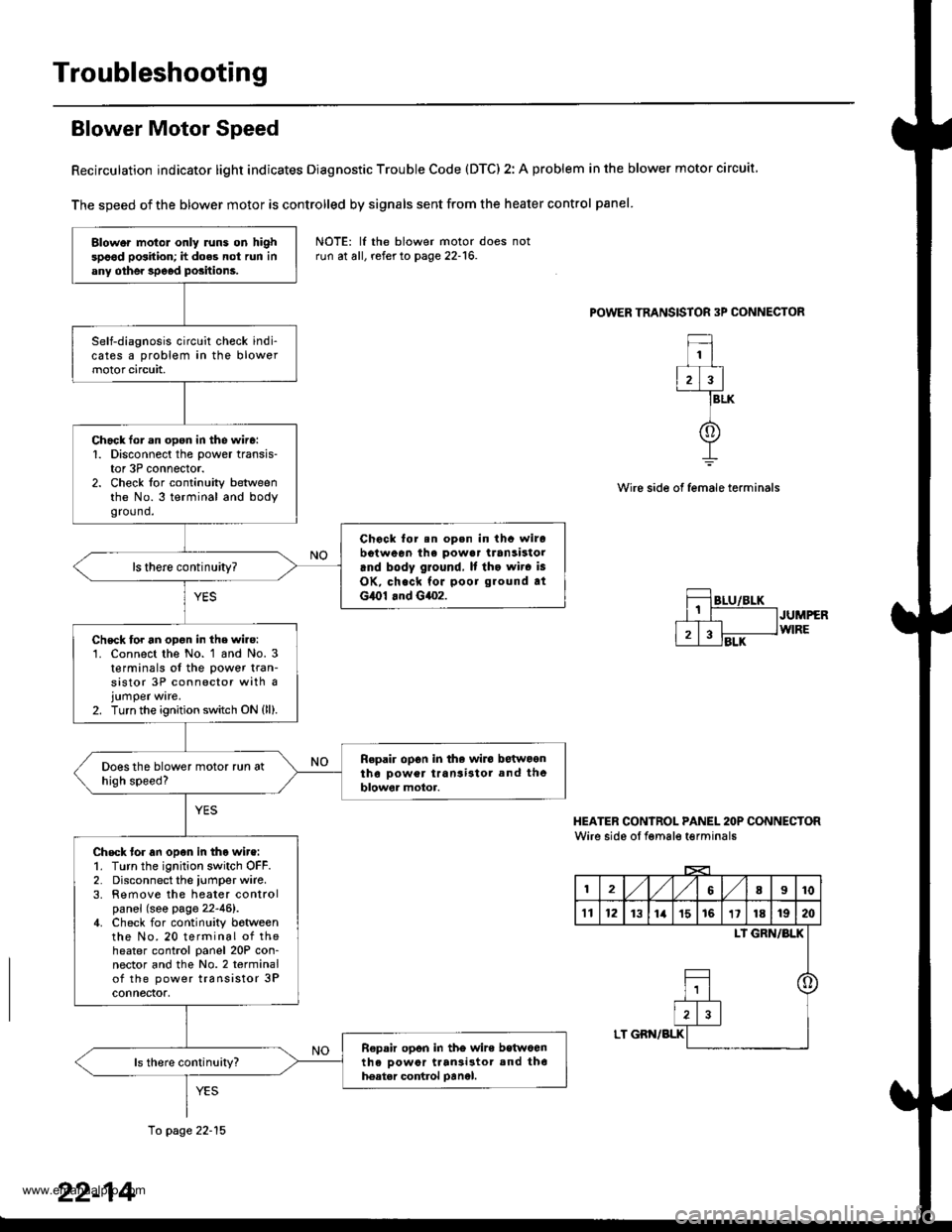
Blower Motor Speed
Recirculation indicator light indicates Diagnostic Trouble Code (DTC) 2: A problem in the blower motor circuit
The speed of the blower motor is controlled by signals sent from the heater control panel
POWER TRANSISTOR 3P CONNECTOR
1
2)3
f
BLK
Wire side of female terminals
JUMPERWIRE
HEATER CONIROL PANEL 2OP CONNECTORWire side oI fgmale t€rminals
12,/1,/68I10
't112131ia't51611181920
LI GRN/BLK
o
LT GBN/BLK
Blower motol only runs on highspood position; h does not run inany othe. speod positions.
Self-diagnosis circuit check indi-cates a problem in the blowermotor circuit,
Chack lor.n open in the wire:1. Disconnect the power transis-tor 3P connector.2. Check for continuity betweenthe No.3 terminal and bodygro(1nd.
Chock for.n op.n in thc wirobotween ihe powa. transistorrnd body ground, It tho wir. is
OK, check for poor ground atG,O1 .nd G4o2.
ls there continuity?
Chsck for an opon in the wire:'1. Connect the No. 1 and No. 3t€rminals of the power tran-sistor 3P connector with ajumper ware.2. Turn the ignition switch ON {ll).
Repair op6n in the wiro betwoontho Dower transi3tol and theblowor motor.
Check tor an open in tho wire:1. Turn the ignition switch OFF.2. Disconnect the iumper wire.3. Remove the heater controlpanel (see page 22-46).4. Check for continuity botweenthe No. 20 terminal of theheater control panel 20P con-nector and the No.2 terminalof the power transistor 3Pconnectof,
R€pair opon in tho wire betwoenth6 oowor ttan3i3tor and th6hoatar control oanel.
NOTE: lf the blower motor doesrun at all, refer to page 22-16.
10 page 22-15
22-14
www.emanualpro.com
Page 1106 of 1395
Troubleshooting
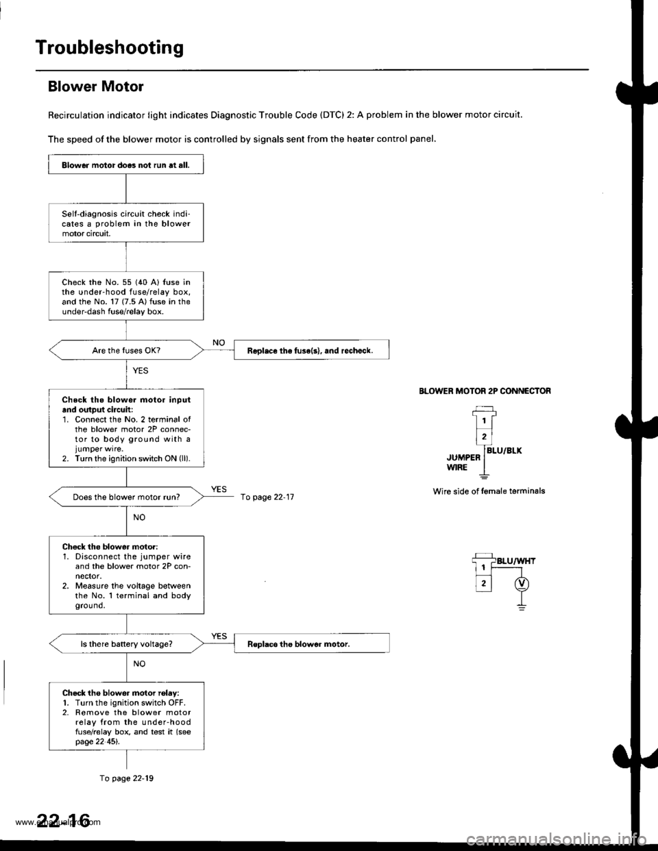
Blower Motor
Recirculation indicator light indicates Diagnostic Trouble Code (DTC) 2: A problem in the blower motor circuit.
The speed of the blower motor is controlled by signals sent from the heater control panel,
BLOWER MOTOR 2P CONNECTOR
JUMPEFw|RE
Wire side of lemale terminals
Blower motor do.3 not run at all.
Selt-diagnosis circuit check indi-cates a problem in the blowermotor circuit,
check rhe No. 55 (40 A) {use inthe under-hood fuse/relay box,and the No. 17 (7.5 A) fuse in theunder-dash fuse/relay box.
Replace th6 fuse(s), and rechalck.
Check tho blowe. motor inputand output cilcuh:1. Connect the No. 2 terminal ofthe blower motor 2P connec-tor to body ground with ajumper wrre.2. Turn the ignition switch ON (ll).
Does the blower motor run?
Chock the blower moto.:1. Disconnect the jumper wireand the blower motor 2P con-nector.2. Measure the voltage betweenthe No. l terminal and bodygrou nd.
Check tho blower motor rolay:1. Turn the ignition switch OFF.2. Romove the blower motorrelay from the under-hoodfuse/relay box, and test it (seepage 22 45l'.
fo page 22-11
fo page 22-19
22-16
www.emanualpro.com
Page 1152 of 1395
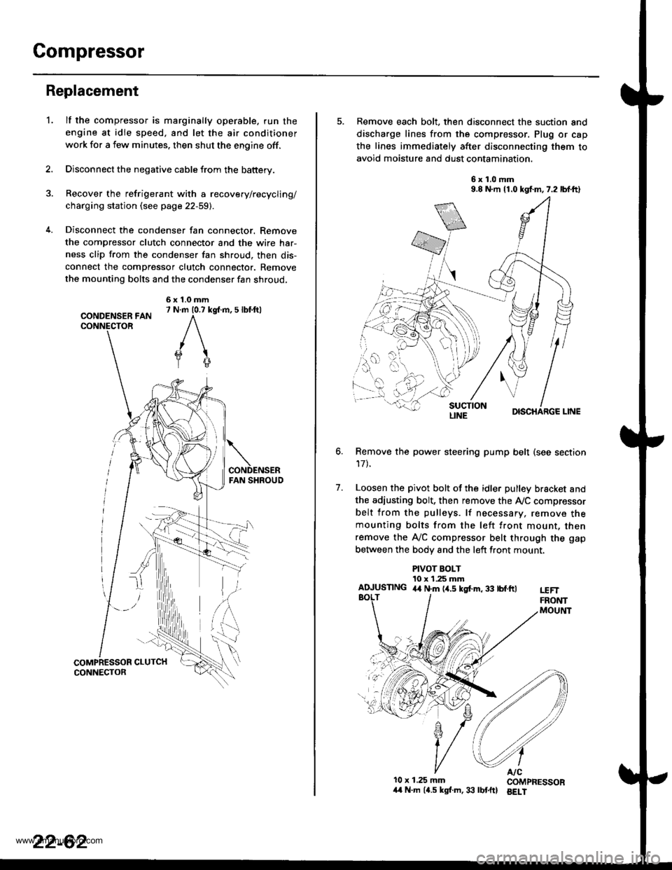
Compressor
Replacement
lf the compressor is marginally operable. run the
engine at idie speed, and let the air conditioner
work for a few minutes. then shut the engine off.
Disconnect the negative cable from the battery.
Recover the refrigerant with a recovery/recycling/
charging station (see page 22-59).
Disconnect the condenser fan connector. Remove
the compressor clutch connector and the wire har-
ness clip from the condenser fan shroud, then dis-
connect the compressor clutch connector. Remove
the mounting bolts and the condenser fan shroud,
CONDENSER FANCONNECTOR
6x1.0mm7 N.m 10.7 kg{.m, 5 lbl.ftl
'L
2.
5. Remove each bolt, then disconnect the suction and
discharge lines from the compressor. Plug or cap
the lines immediately after disconnecting them to
avoid moisture and dust contamination,
6x1.0mm9.8 N.m 11.0 kgf.m,7.2 lbf.ft)
DISCHARGE LINE
Remove the power steering pump belt (see section
17t.
Loosen the pivot bolt of the idler pulley bracket and
the adiusting bolt, then remove the Ay'C compressor
belt from the pulleys. lf necessary, remove themounting bolts from the left front mount, thenremove the A,/C compressor belt through the gap
between the bodv and the left front mount.
6.
7.
PIVOT BOLT10 x 1.25 mmAIUUSTING 4,t N.m (4.5 kgf.m, 33 tbf.ftlt€FTFRONTMOUltlT
10x 1.25 mm COMPRESSOR/t4 N.m (4.5 kgl.m,33 lbtftl BELI
LINE
www.emanualpro.com
Page 1161 of 1395

Body Electrical
Speciaf Toofs ,...,..,.............-.23-2
Troubleshooting
Tips and Precautions ......,.,..........,.................. 23-3
Five-step Troubleshooting ........,.,.,...,,.,......... 23-5
Wire Color Codes ...,....,.. 23-5
Relay and Control Unit Locations
Engine Compartment ..,.,......,......................... 23-6
Dashboard ,.,.,..............-.- 23-7
Door ....................... .........23-10
Index to Cilcuits and Sysiems
Accessory Socket .. ,....,.,..,.,. 23-95*Airbags ................ .,....,. Sestion 24
Air Conditioning ,.,.,.... Section 22
Alternator ................... Section 4
Anti-lock Brake System {ABSI ................... Section 19'A/T Gear Position Indicator ....................... Section 1,1
Automatic Transmission System ...........,.. Section 14
Battery ................... ..............23-50
Blower Controls .,...,.,, Section 22
Charging System ....... Seqtion il
Clock -'98 Model ................ 23-98
Connector ldentification and Wire HarnessRouting .................. ......... 23.11
Cruise Control ............ Ssction 4
Dash Lights Brightness Contlo||er ..................... 23-90
Fan Conlrols ...,......,.... Section 10
Fuel Pump ,..,.,...,....,.... Section 11
Fuses...................... .,,.,.,.,.,,.,23-40*Gauges
Circuit Diagram ......-....-..23-58
Fuel Gauge .....,.,..... Section 11
Speedometer ..,..........,... 23-56
Ground Distribution ,....,.,...23-46
Hatch Glsss ODenor .........................,.,.,.,.,..,.,.,.,,. 23-121
Heater Controls .-........ Soction 21*Horns.,...,..,.,.,....... ................23"104*fgnition Switch ,,.,.,..,.,.,,.,.,.,23-51
lgnition Key Light System -'97 Mod6l .............. 23.88
-+
BODY
www.emanualpro.com
Page 1174 of 1395
![HONDA CR-V 1998 RD1-RD3 / 1.G Workshop Manual
Connector ldentification and Wire Harness Routing
Engino Wire Harness
Connecto; or
Terminal
Number of
CavitiesLocationConneqts toNotos
c101
c102
c103
c 104
c105
c105
c106
c 107
c 108
c 109
c]10
c1ll HONDA CR-V 1998 RD1-RD3 / 1.G Workshop Manual
Connector ldentification and Wire Harness Routing
Engino Wire Harness
Connecto; or
Terminal
Number of
CavitiesLocationConneqts toNotos
c101
c102
c103
c 104
c105
c105
c106
c 107
c 108
c 109
c]10
c1ll](/img/13/5778/w960_5778-1173.png)
Connector ldentification and Wire Harness Routing
Engino Wire Harness
Connecto; or
Terminal
Number of
CavitiesLocationConneqts toNotos
c101
c102
c103
c 104
c105
c105
c106
c 107
c 108
c 109
c]10
c1l'l
c112
c113
c't 14
cl16
cl16
c117
c118
c119
c120
c121
c't22
c't23
c't25
cl26
cl27
cr 28
cl29
c130
c131
c132
c 133
c134
c134
c135
c 136
10
6
1
2
1
2
1
10
20
31
16
22
l0
l0'14
14
1
Left side of engine compartment
Left side of engine compartment
Middle of engine
Middle of engine
Left side of engine compartment
Left side of engine compartment
Middle of engine
Middle of engine
Middle of engine
Middle of engine
Middle of engine
Middle of engine
Middle of engine
Middle of engine
Middle of engine
Middle of engine
Middle of engine
Middle of engine
Middle of engine
Middle of engine
Middle of engine
Right side of engine
Middle of engine
Behind right kick panel
Under right side of dash
Under right side of dash
Under right side of dash
Under right side of dash
Under right side of dash
Right side of engine
Right side of engine
Middle of engine
Middle of engine
Middle of engine
Middle of engine
Middle of engine
Middle of engine
Left side of engine compartment
Middle of engine
Middle of engine
Main wire harness (C304)
Main wire harness (C305):'97 - 98 models
No. 1 fuel injector
Crankshaft speed fluctuation (CKF) sensor
Alternator
Alternator
Engine oil pressure switch
No.2 fuel injector
Evaporative emission (EVAP) purge
control solenoid valve
No. 3 fuel injector
No. 4 fuel injector
Primary heated oxygen sensor(Primary HO2S) (sensor 1)
Radiator fan switch
Coolant temperature sending unit
Engine coolant temperature (ECT) sensor
Mainshaft speed sensor
Lock-up control solenoid valve
Back-up light switch
Shift control solenoid valve
Linear solenoid valve
Countershaft speed sesnsor
Starter solenoid
Distributor
Junction connector
PCM
ECIWPCM
ECM/PCM
ECM/PCM
Main wire harness (C,|:}1)
IVT gear position switch
Vehicle speed sensor (VSS)
Throttle position (TP) sensor
MAP sensor
ldle air control (lAC)valve
lntake air temperature (lAT) sensor
Junction connector
Junction connector
Power steering pressure (PSP) switch
Junction connector
Knock sensor (KS)
A/r
USA
Canada
Alr
AlT
M/'r
Afi
'97mooel
'97 model'98 - 00
mooets
'99 - 00
models
T101
r102
Left side of en0ine companment
Right side of engine compartment
Alternator
Under-hood fuse/relay box
G101Middle of engineEngine ground, via engine wire harness
23-14
www.emanualpro.com
Page 1206 of 1395

Ground Distribution
Ground-to-Component(sl Index
GroundWire Color
G2
G3
G 10'l
G201
G202
G351
BLIVRED
BRN
BLK
BLK
BRN/BLK
BLK
BLK
BLK
23-46
Component or Circuits Grounded
Battery
Valve Cover
Transmission housing
A,/T gear position switch
ECM (PG1, PG2) ('98 - 00 models: M/T)
PCM (PG1, PG2l (Avrr)
PGM-FI main relay
Power steering pressure (PSP) switch
Radiator fan switch
VSS
Data link connector
ECM (1G1, LG2) ('98 - 00 models: M/T)
PCM (LGI, LG2) (IVT)
Shielding:
between ECM ('98 - 00 models: M/T) or PCM (Ay'T) and CKF sensorbetween ECM {'98 - 00 modets: M/T} or pCM (Ay'T) and CKp sensorbetween ECM ('98 - 00 models: M/T) or PCM (rVT) and CYP sensorbetween ECM ('98 - 00 models: M/T) or PCM (Ay'T) and TDC sensorbetween ECM {'98 - 00 models: M/T) or PCM (ly'T) and countershaft speed sensor (Ay'T)
between ECM ('98 - 00 models: M/T) or PCM {A,,/T) and mainshaft sp€ed sensor {!VT)between ECM ('98 - 00 models: M/T) or PCM (A,/T) and primary HO2Sbetween ECM ('98 - 00 models: M/T) or PCM (Ay'T) and secondary HO2SHorn (High)
Horn {Low}
Radiator fan motor
Right headlight
Right front parking light
Right front side marker light
Right front turn signal light
Condenser fan motor
Cruise actuator
Left front parking light
Left front side marker light
Left front turn signal light
Left headlight
Rear window washer motor
Windshield washer motor
ABS pump motor
www.emanualpro.com
Page 1215 of 1395
Gauge Assembly
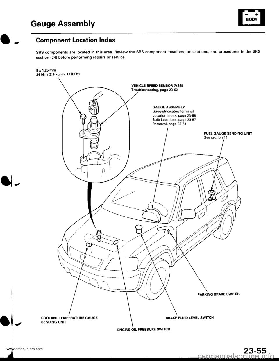
Component Location Index
SRS components are located in this area. Review the SRS component locations, precautions, and procedures in the SRS
section {24} before performing repairs or service.
I x 1.25 mm24 N.m {2.4
VEHICLE SPEED SENSOF {VSS'Troubleshooting, page 23-62
GAUGE ASSEMBLYGau ge/lndicator/TerminalLocation Index, page 23-56Bulb Locations, page 23-57Removal, page 23-61
J-
FUEL GAUGE SENDING UNITSee section 1 l
PARKING BRAKE SWITCH
COOLANT TEMPERATURE GAUGESENDING UNITBRAKE FLUID LEVEL SWITCH
ENGINE OIL PRESSURE SWITCH
www.emanualpro.com
Page 1216 of 1395
Gauge Assembly
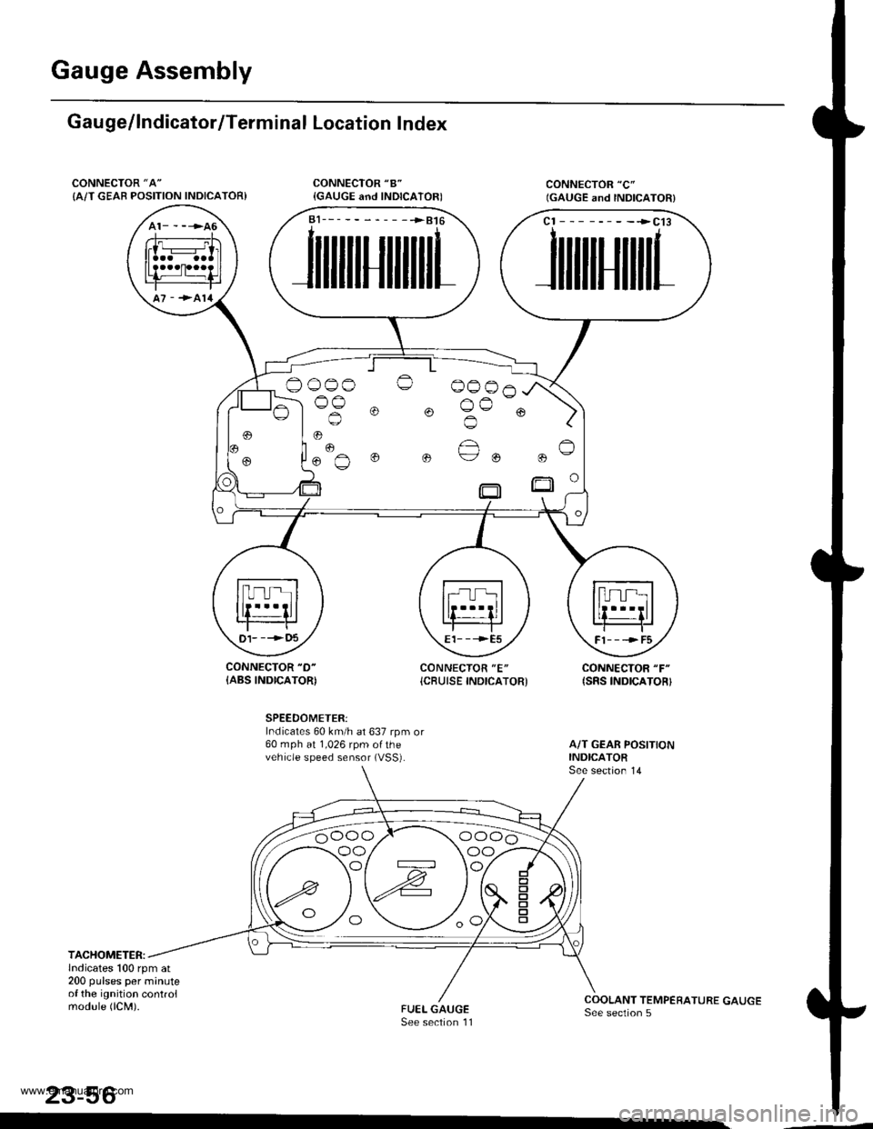
Gau ge/lndicator/Terminal Location Index
CONNECTOR "A"
{A/T GEAB POSITION INDICATOR)
CONNECTOR "D-
{ABS INDICATOR)CONNECTOR "E"
{CBUISE INDICATOR'CONNECTOR "F"
{SRS INDICATOR}
SPEEDOMETER:Indicates 60 km/h at 637 rpm or60 mph at 1,026 rpm ofthevehicle speed sensor (VSS).
TACHOMETER:lndicates 100 rpm at200 pulses per minuteof the ignition controlmodule (lCM).
23-56
a1___-__-____>816
JilililIJililil1
cl --------->cl3
JililtHililL
,
.. "€""^
o o ue ou
t)1- --->t)5E1- - -->E5Fl---->F5
oo/ \oo
www.emanualpro.com