20-1 HONDA CR-V 1998 RD1-RD3 / 1.G User Guide
[x] Cancel search | Manufacturer: HONDA, Model Year: 1998, Model line: CR-V, Model: HONDA CR-V 1998 RD1-RD3 / 1.GPages: 1395, PDF Size: 35.62 MB
Page 996 of 1395
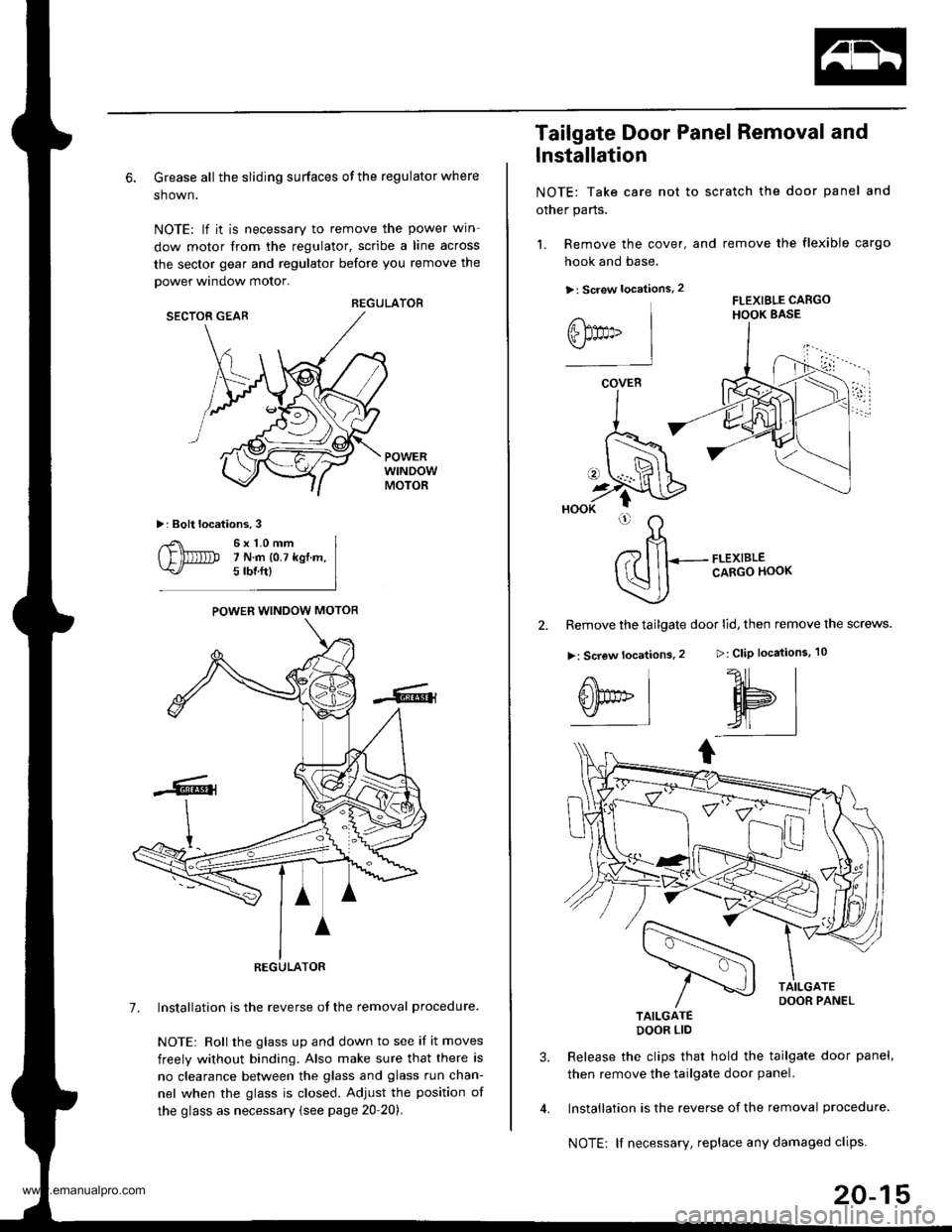
6. Grease all the sliding surfaces of the regulator where
shown.
NOTE: lf it is necessary to remove the power win-
dow motor from the regulator, scribe a line across
the sector gear and regulator before you remove the
power window motor.
REGULATORSECTOR GEAB
POWERwtNDowMOTOR
>: Bolt locations.3
6x1.0mm7 N.m 10.7 kgf.m,5 rbnftl
POWER WINDOW MOTOR
REGULATOR
7. lnstallation is the reverse of the removal procedure.
NOTEr Roll the glass up and down to see if it moves
freely without binding. Also make sure that there is
no clearance between the glass and glass run chan-
nel when the glass is closed. Adjust the position of
the glass as necessary {see page 20 20).
1. Remove the cover,
hook and base.
>: Screw locations.2
Tailgate Door Panel Removal and
lnstallation
NOTE: Take care not to scratch the door panel and
other parts.
and remove the flexible cargo
FLEXIBLE CARGOHOOK BASE
>: CliP locations.
?11 |
HPI,4| |
I
FLEXIBLECARGO HOOK
2. Remove the tailgate door lid, then remove the screws.
>: Screw locations.2
TAILGATEDOOR LIO
Release the clips that hold the tailgate door panel,
then remove the tailgate door panel.
Installation is the reverse of the removal procedure.
NOTE: lf necessary, replace any damaged clips.
3.
@t"
COVER
i
20-15
www.emanualpro.com
Page 997 of 1395
Doors
License Plate Trim Removal and
Installation
CAUTION: Put on gloves to prolest your hands.
NOTE: Take care not to scratch the license plate trim
and tailgate door.
'1. Remove the license olate.
2. Remove the tailgate door panel (see page 20-15).
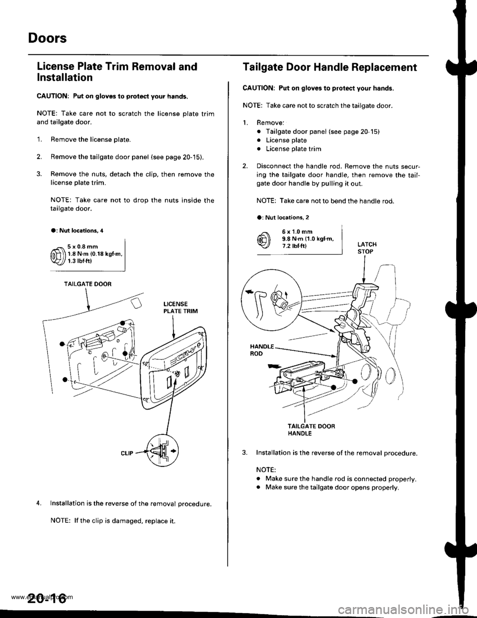
3. Remove the nuts, detach the clip, then remove the
license olate trim.
NOTE: Take care not to drop the nuts inside the
tailgate door.
a: Nut loc.lions.4
5x0.8mm1.8Nm(0.18kgt.m.1.3 rbf.ft)
4. Installation is the reverse of the removal procedure.
NOTE: lf the clip is damaged, replace it.
20-16
TAILGATE DOOR
Tailgate Door Handle Replacement
CAUTION; Put on gloves to protecl your hands,
NOTE: Take care not to scratch the tailgate door.
1. Remove:
. Tailgate door panel (see page 20,15)
. License plate
. License plate trim
2. Disconnect the handle rod. Remove the nuts secur-
ing the tailgate door handle, then remove the tail-gate door handle by pulling it out.
NOTE: Take care not to bend the handle rod.
6x1.0mm9.8 N.m {1.0 kgtm,7.2 rbtft)
TAILGATE DOORHANDLE
Installation is the reverse of the removal procedure.
NOTE:
. Make sure the handle rod is connected properly.
. Make sure the tailgate door opens propedy.
a: Nut locations,2
,Is
www.emanualpro.com
Page 998 of 1395
Tailgate Door Latch and Latch Stop Replacement
CAUTION: Put on gloves to protect your hands.
NOTE: Take care notto scratch the tailgate door.
'1. Remove the tailgate door panel (see page 20-15).
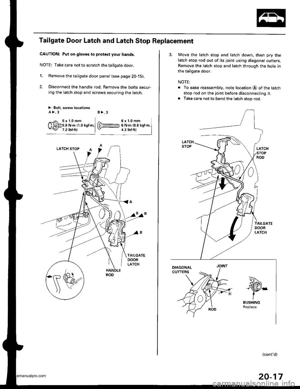
2. Disconnect the handle rod. Remove the bolts secur-
ing the latch stop and screws securing the latch.
>: Bolt, screw locationsA>,3 B>,3
6x1.0mm
3. Move the latch stop and latch down, then pry the
latch stop rod out of its joint using diagonal cutters.
Remove the latch stop and latch through the hole in
the tailgate door.
NOTE:
. To ease reassembly, note location @ of the latch
stop rod on the joint before disconnecting it.. Take care not to bend the latch stop rod.
''-t.-Ngta
-\S/r
tBUSHING
(cont'd)
20-17
www.emanualpro.com
Page 999 of 1395
Doors
Tailgate Door Latch and Latch Stop
Replacement (cont'd)
4. lnstallation is the reverse of the removal orocedure.
NOTE:
. Make sure the handle rod and latch stop rod are
connected properly.
a Make sure the tailgate door locks and opens prop-
env.
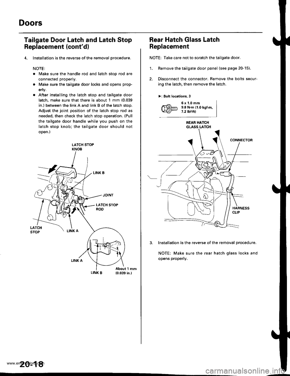
. After installing the latch stop and tailgate door
latch, make sure that there is about 1 mm {0.039
in.l between the link A and link B of the latch stop.
Adjust the joint position of the latch stop rod as
needed, then check the latch stop operation. (Pull
the tailgate door handle while you push on the
latch stop knob; the tailgate door should not
oDen.)
LATCH STOPKNOE
20-18
Rear Hatch Glass Latch
Replacement
NOTE: Take care not to scratch the tailgate door.
'1. Remove the tailgate door panel (seepage20-15).
2. Disconnect the connector. Remove the bolts secur-
ing the latch, then remove the latch.
>: Boh locations, 3
6x1.0mm9.8 N.m {1.0 kgI.m,7.2 tbl.Itl
REAR HATCHGLASS LATCH
3. Installation is the reverse of the removal procedure.
NOTE: Make sure the rear hatch glass locks and
opens properly.
www.emanualpro.com
Page 1000 of 1395
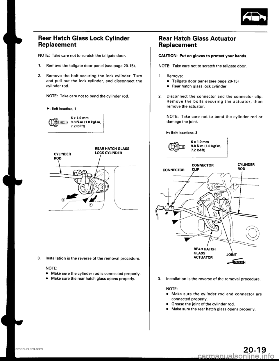
Rear Hatch Glass Lock Cylinder
Replacement
NOTE: Take care not to scratch the tailgate door.
1. Remove the tailgate door panel (see page 20-15).
2. Remove the bolt securing the lock cylinder. Turn
and pull out the lock cylinder, and disconnect the
cylinder rod,
NOTE: Take care not to bend the cylinder rod.
>: Bolt location. 1
6x1.0mm9.8 N.m {1.0 kg .m,
7 .2 tbt.lll
REAR HATCH GLASS
J.Installation is the reverse of the removal procedure.
NOTE:
. Make sure the cylinder rod is connected properly.
. Make sure the rear hatch glass opens properly.
Rear Hatch Glass Actuator
Replacement
CAUTION: Put on gloves to protsct your hands.
NOTE: Take care not to scratch the tailgate door.
1. Remove;
o Tailgate door panel (see page 20-'15)
. Rear hatch glass lock cylinder
2. Disconnect the connector and the connector clip.
Remove the bolts securing the actuator, then
remove the actuator.
NOTE: Take care not to bend the cylinder rod or
damage the joint.
>: Bolt locations, 3
6x1.0mm9.8 N.m 11.0 kgt.m,7.2 tbt.ft)
CONNECTOR
CONNECTOR
REAR HATCHGLASSACTUATORJOINT
-6{
Installation is the reverse of the removal procedure.
NOTE:
. Make sure the cylinder rod and connector are
connected properly.
. Grease the joint of the cylinder rod.
. Make sure the rear hatch glass opens properly.
20-19
www.emanualpro.com
Page 1056 of 1395
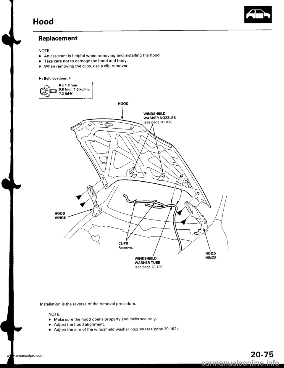
Hood
Replacement
NOTE:
. An assistant is helpful when removing and installing the hood.
a Take care not to damage the hood and body
. When removing the clips, use a clip remover.
>: Bolt locations, 4
6x1.0mm9.8 N.m {1.0 kgt.m,7.2 tbtfr)
WINDSHIELDWASHER NOZZLES(see page 20-100)
G
{
\HOODHINGEWINDSHIELDWASHER TUBE(see page 20-100)
Installation is the reverse of the removal procedure
NOTE:
. Make sure the hood opens properly and locks securely.
. Adjust the hood alignment.
. Adjust the aim of the windshield washer nozzles (see page 20-102)
HOOD
20-75
www.emanualpro.com
Page 1059 of 1395
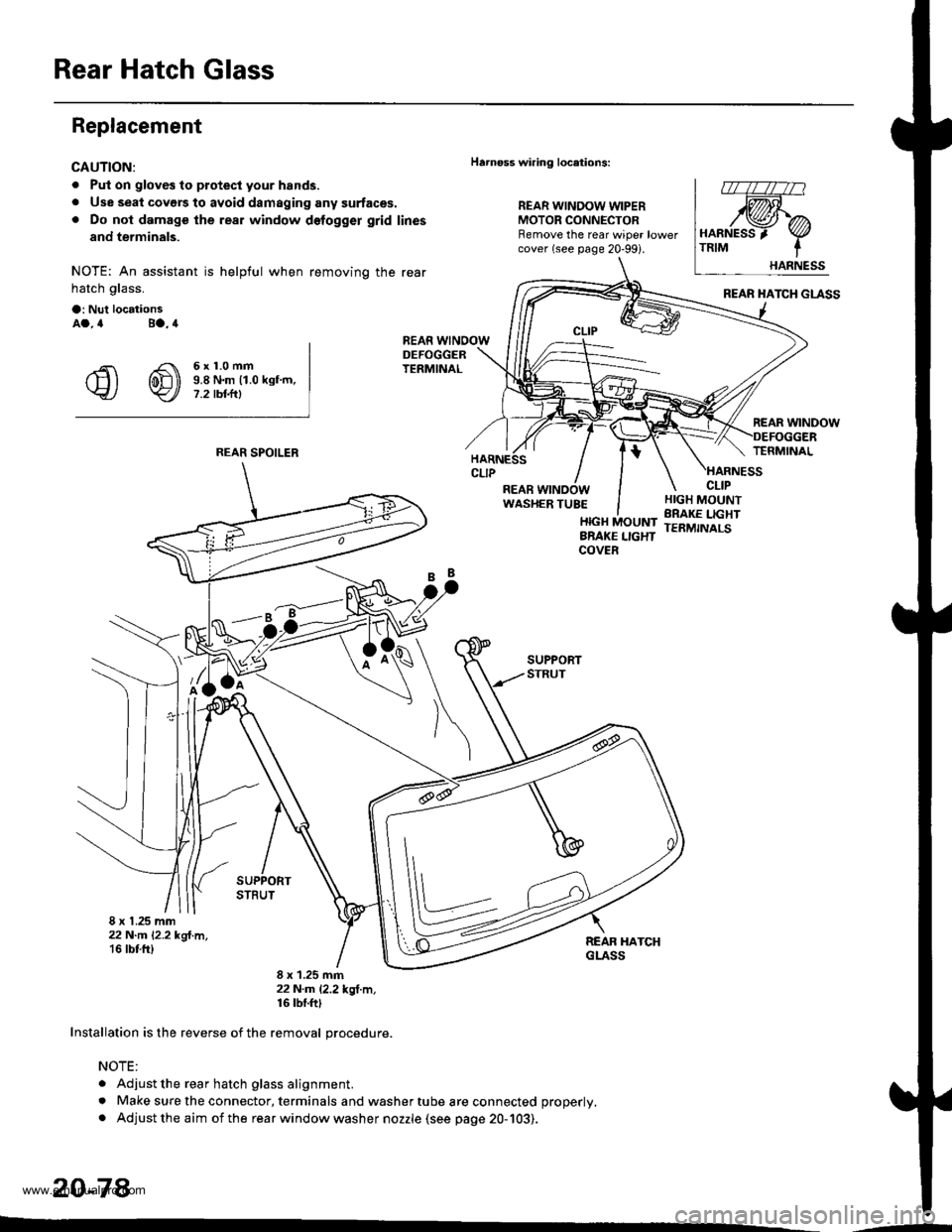
Rear Hatch Glass
Replacement
CAUTION:
. Put on gloves to protecl your hands.
. Use seal covers to avoid damaging any surfaces.. Do not damage the rear window delogger grid lines
and terminals.
NOTE: An assistant is helpful when removing the rear
hatch glass.
a: Nul locationsAa.4 Ba.4
€ @ i!iff*-"-
Harnoss wiring locations:
REAR WINDOW WIPERMOTOR CONNECTORRemove the rear wiper lowercover (see page 20-99i.
HARNESS 'TRIM
.;=-
8 x 1.25 mm22 N-m l'2.2 kgl.m,'16 tbt fr)
8 x 1.25 mm22N.m l.2.2*ql.m,16 tbf.ft|
Installation is the reverse of the removal orocedure.
NOTE:
. Adjust the rear hatch glass alignment.
. Make sure the connector, terminals and washer tube are connected properly.
. Adjust the aim of the rear window washer nozzle (see page 20-103).
20-78
REAR SPOILER
'--
www.emanualpro.com
Page 1078 of 1395
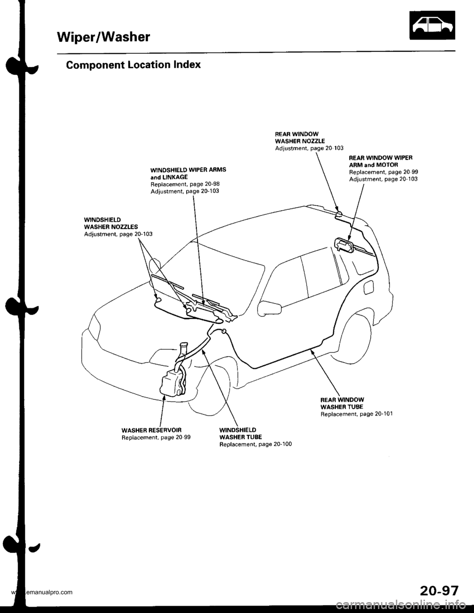
Wiper/Washer
Component Location Index
WINOSHIELD WIPER ARMS
and LINKAGEReplacement, page 20-98
Adiustment, Page 20-103
REAR WINDOW WIPERARM and MOTORReplacement, page 20 99Adiustment, page 20 103
WASHER RESERVOINReplacement, page 20 99WASHER TUBEReplacement, page 20-100
20-97
www.emanualpro.com
Page 1079 of 1395
Wiper/Washer
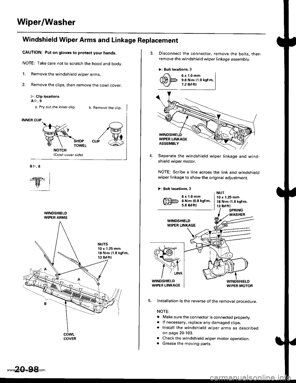
Windshield Wiper Arms and Linkage Replacement
CAUTION: Put on gloves to protoct your hands.
NOTE: Take care not to scratch the hood and body.
1. Remove the windshield wiper arms.
2. Remove the clips, then remove the cowl cover.
>: Clip locationsA>.9
b. Remove the clip.
SHOPTOWEL
(Cowl cover side)
/G
"rr/ &
a. Pry out the anner clip.
INNER CLIP
B>.8
ql
WINDSHIELDWIPER ARMS
NUTS'10 x 1.25 mm18 N.m 11.8 kgf.m.13 tbf.ftl
COVER
20-98
3. Disconnect the connector, remove the bolts, then
remove the windshield wiper linkage assembly.
>: Boh locations,3
4. Separate the windshield wiper linkage and wind-shield wiper motor.
NOTE: Scribe a line across the link and windshieldwiper linkage to show the original adjustment.
>: Boh locations, 3
s}@
1ffi,
/Y{
/
' L|NK
WINDSHIELDWIPER LIN(AGEWIPER MOTOR
5. Installation is the reverse of the removal procedure.
NOTE:
. Make sure the connector is connected properly.. lf necessary. replace any damaged clips.. Install the windshield wiper arms as describedon page 20-103.
. Check the windshield wiper motor operation.. Grease the moving parts.
6x1.0mm9.8 N.m (1.0 kglm,7.2 tbt.fr)
6x1.0mm8 N.m 10.8 kgf.m,5.8 lbf.ftl
NUT10 x 1.25 mm18 N.m 11.8 kgf.m,13 tbf.ftlSPRINGWASHER
www.emanualpro.com
Page 1080 of 1395
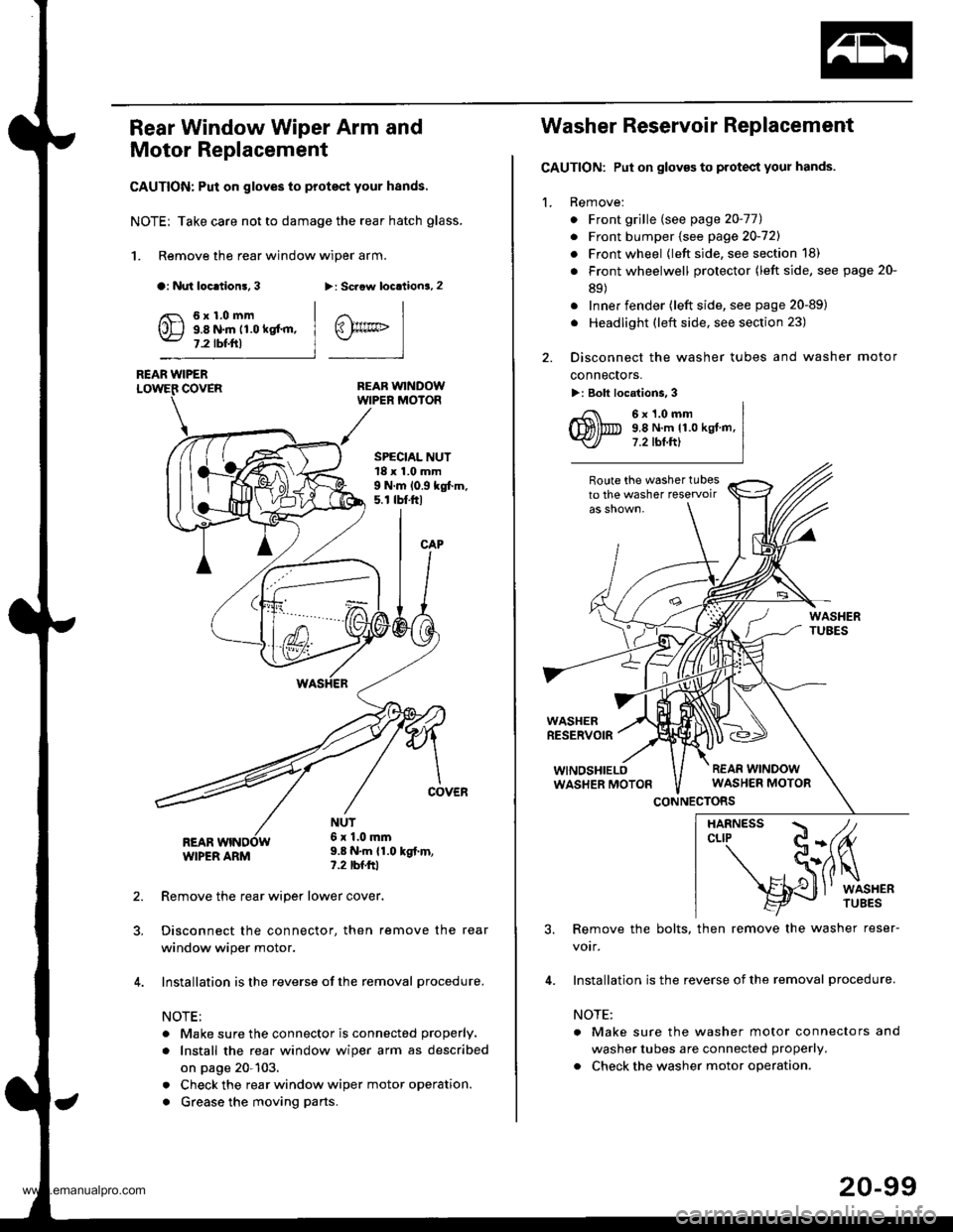
Rear Window Wiper Arm and
Motor Replacement
CAUTION: Put on gloves to protect your hands.
NOTE; Take care not to damage the rear hatch glass.
1. Remove the rear window wiper arm.
a: Nut loc.tion!, 3>: Scaow locationa, 2
REAR WINDOWWIPER MOIOR
REAR WIPERCOVER
REARWIPER ARM
6x1.0mm9.8 N.m 11.0 kgt'm,7.2 tbf.ftl
SPECIAL NUT18 x 1.0 mm9 N.m 10.9 kgt m,5. r tbt.ftl
NUT6x 1.0mm9.8 N.m {1.0 kgt.m,?.2 tbfftl
Remove the rear wiper lower cover.
Disconnect the connector, then remove the rear
window wiper motor.
Installation is the reverse of the removal procedure.
NOTE:
. Make sure the connector is connected properly.
. Install the rea. window wiper arm as described
on page 20-103.
. Check the rear window wiper motor operation.
. Grease the moving parts.
@rrc
Washer Reservoir Replacement
GAUTION: Put on gloves to protect your hands.
1. Remove:
. Front grille (see page 20-771
. Front bumper (see page 20-721
. Front wheel {left side, see section 18)
. Front wheelwell protector (left side, see page 20-
89)
. Inner fender (left side, see page 20-89)
. Headlight (left side, see section 23)
2. Disconnect the washer tubes and washer motor
connectors.
>: Bolt locations, 3
6x1.0mm9,8 N.m 11.0 kgt.m,7.2 tbt.ftl
Route the washer tubesto the washer teservoir
WASHERRESERVOIR
WINOSHIELOWASHER MOTON
CONNECTORS
3. Remove the bolts, then remove the washer reser-
votr,
4. Installation is the reverse of the removal procedure.
NOTE:
a Make sure the washer motor connectors and
washer tubes are connected properly.
. Check the washer motor operation.
HARNESS / tcLrP C-(fu
- S(ilq
s{J
l' wrsHER
20-99
www.emanualpro.com