Clutch solenoid circuit HONDA CR-V 1998 RD1-RD3 / 1.G User Guide
[x] Cancel search | Manufacturer: HONDA, Model Year: 1998, Model line: CR-V, Model: HONDA CR-V 1998 RD1-RD3 / 1.GPages: 1395, PDF Size: 35.62 MB
Page 550 of 1395
Description
Hydraulic Flow (cont'dl
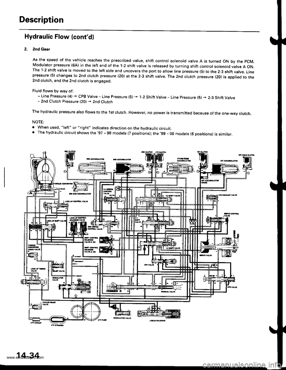
2nd Gsar
As the speed of the vehicle reaches the prescribed value. shift control solenoid valve A is turned ON by the pCM.Modulator pressure (6A) in the left end of the 1-2 shift valve is released by turning shift control solenoid valve A ON.The 1-2 shift valve is moved to the left side and uncovers the port to allow line pressure (5) to the 2-3 shift vatve. Linepressure (5) changes to 2nd clutch pressure (20) at the 2-3 shift valve, The 2nd clutch pressure {20) is appli€d to the2nd clutch. and the 2nd clutch is engaged.
Fluid flows by way of:- Line Pressure (4) + CPB Valve - Line Pressure (5) * 1-2 Shift Valve - Line pressure (S) * 2-3 Shift Valve- 2nd Clutch Pressure (20) - 2nd Clutch
The hydraulic pressure also flows to the lst clutch. However, no power is transmitted because of the one-wav ctutch.
NOTE:
. When used, "|eft" or "right" indicates direction on the hydraulic circurr_' The hydraulic circuit shows the'97 - 98 models (7 positions); the '99 - 00 models (6 positions) is similar,
14-34
www.emanualpro.com
Page 551 of 1395
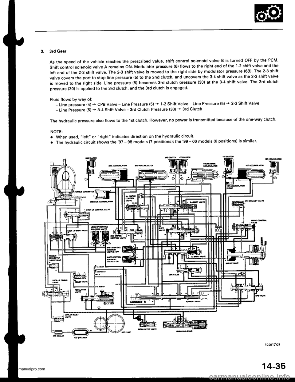
3. 3rd Gear
As the speed of the vehicle reaches the prescribed value. shift control solenoid valve B is turned OFF by the PCM.
Shift control solenoid valve A remains ON. Modulator pressure (6) flows to the right end of the 1-2 shift valve and the
left end of the 2-3 shift valve. The 2-3 shift valve is moved to the right side by modulator pressure (68) The 2-3 shift
valve covers the port to stop line prsssure (5) to the 2nd clutch. and uncovers the 3-4 shift valve as the 2-3 shift valve
is moved to the right side, Line pressure (5) becomes 3rd clutch pressure (30) at the 3-4 shift valve. The 3rd clutch
pressure (30) is applied to the 3rd clutch, and the 3rd clutch is engaged.
Fluid flows by way of:- Line pressure (4) - CPB Valve - Line Pressure (5) * 1-2 Shift Vaiv€ - Line Pressure (5) * 2-3 Shift Valve
- Line Pressure (5) * 3-4 Shift Valve - 3rd Clutch Pressure (30) * 3rd Clutch
The hvdraulic Dressure also flows to the 1st clutch. However, no power is trsnsmitted because of the one-way clutch.
NOTE:
. When used, "|eft" or "right" indicates direction on ths hydraulic circuit.
. The hvdraulic circuit shows the '97 - 98 models (7 positions); the'99 - 00 models (6 positions) is similar.
(cont'd)
14-35
www.emanualpro.com
Page 552 of 1395
Description
Hydraulic Flow (cont'd)
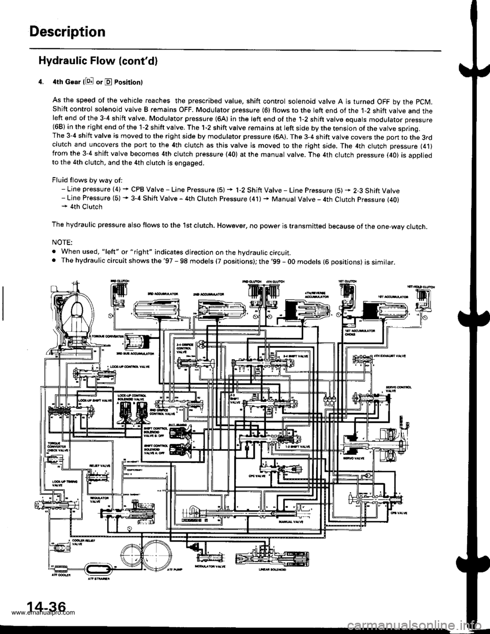
4th Gear llQ! or E Posirion)
As the speed of the vehicle reaches the prescribed value. shift control solenoid valve A is turned OFF by the pCM,
Shift control solenoid valve B remains OFF. Modulator pressure (6) flows to the left end of the 1-2 shift valve and theleft end of the 3-4 shift valve. Modulator pressure (64) in the left end of the 1-2 shift valve equals modulator pressure(68) in the right end of the 1-2 shift valve. The 1-2 shift valve remains at left side by the tension of the valve spring.The 3-4 shift valve is moved to the right side by modulator pressure (6A). The 3-4 shift valve covers the pon to the 3rdclutch and uncovers the port to the 4th clutch as this valve is moved to the right side, The 4th clutch pressure (41)from the 3-4 shift valve becomes 4th clutch pressure (40) at the manual valve. The 4th clutch pressure (40) is appliedto the 4th clutch, and the 4th clutch is engaged.
Fluid flows by way of:- Line pressure (4) + CPB Valve - Line Pressure (5) + l-2 Shift Valve - Line Pressure {5) * 2-3 Shift Valve- Line Pressure (5) + 3-4 Shift Valve - 4th Clutch Pressure (41) + Manual Valve - 4th Clutch Pressure (40)+ 4th Clutch
The hydraulic pressure also flows to the lst clutch. However, no power is transmitted because of the one-wav clutch.
NOTE:
. When used, "lelt" or " tight" indicates direction on the hydraulic circuit.. The hydrau lic circuit shows the '97 - 98 models (7 positions); the '99 - 0O models (6 oositions) issimilar.
14-36
www.emanualpro.com
Page 553 of 1395
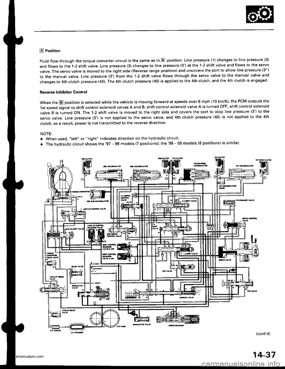
E Position
Fluid flow through the torque converter circuit is the same as in N position. Line pressure (1) changes to line pressure (3)
and flows to the 1-2 shift valve. Line pressure (3) changes to line pressure (3') at the 1-2 shift valve and flows to the servo
vaive. The servo valve is moved to the right side (Reverse range position) and uncovers the port to allow line pressure (3")
to the manual valve. Line pressure (3') from the 1-2 shift valve flows through the servo valve to the manual valve and
changes to 4th clutch pressure (40). The 4th clutch pressure (40) is applied to the 4th clutch, and the 4th clutch is engaged.
R€verse Inhibitor Control
When the @ position is selected while the vehicle is moving forward at speeds over 6 mph (10 km/h), the PCM outputs the
1st speed signal to shift control solenoid valves A and B; shift control solenoid valve A is turned OFF, shift control solenoid
valve B is turned ON. The 1-2 shift valve is moved to the right side and covers the port to stop line pressure (3') to the
servo valve. Line pressure {3') is not applied to the servo valve, and 4th clutch pressure (40} is not applied to the 4th
clutch, as a result, power is not transmitted to the reverse direction.
NOTE:
. When used, "lelt" ot " right" indicates direction on the hydraulic circuit.
. The hvdraulic circuit shows the '97 - 98 models (7 positions); the '99 - 00 models (6 positions) is similar'
(cont'd)
14-37
www.emanualpro.com
Page 557 of 1395
TOROUE CONVERTER
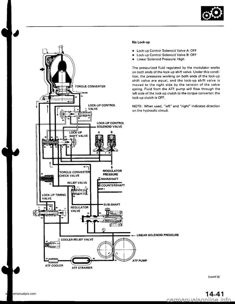
No Lock-up
. Lock-up Control Solenoid Valve A: OFF
. Lock-up Control Solenoid Valve B: OFF
. Linear Solenoid Pressure: High
The pressurized fluid regulated by the modulator works
on both ends of the lock-up shift valve. Under this condi-
tion, the pressures working on both ends of the lock-up
shift valve are equal. and the lock-up shift valve is
moved to the right side by the tension of the valve
spring. Fluid trom the ATF pump will flow through the
left side of the lock-up clutch to the torque converter; the
lock-up clutch is OFF.
NOTE: When us€d, "|eft" and "right" indicates direction
on the hydraulic circuit.
+ LINEAR SOLENOID PRESSURE
(cont'd)
LOCK.UP CONTROLSOI-ENOID VALVE
MOOULATORPRESSURE
MAINSHAFT
COUNTERSHAFTRELIEF VALVE
LOCK-UP TIMINGVALVE
i COOLER RELIEF VALVE
ATF STRAINERATF COOLER
ATF PUMP
14-41
www.emanualpro.com
Page 558 of 1395
Description
Lock-up System (cont'dl
a
a
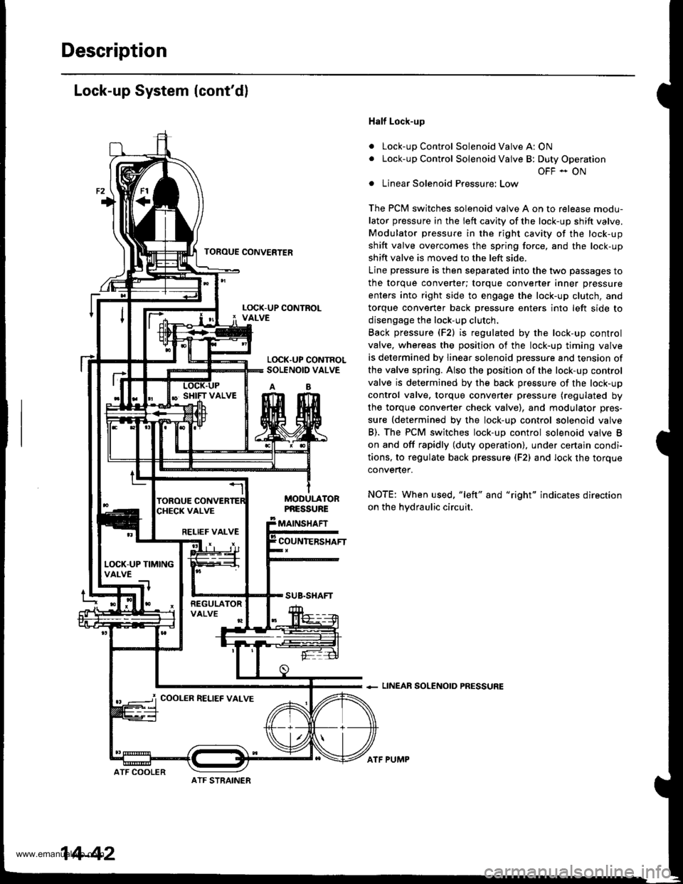
Half Lock-up
Lock-up Control Solenoid Valve A: ON
Lock-up Control Solenoid Valve B: Duty Operation
OFF - ON
Linear Solenoid Pressure: Low
The PCM switches solenoid valve A on to release modu-
lator pressure in the left cavity of the lock-up shift valve.
Modulator pressure in the right cavity of the lock-up
shift valve overcomes the spring force, and the lock-up
shift valve is moved to the left side.
Line pressure is then separated into the two passages to
the torque converter; torque converter inner pressure
enters into right side to engage the lock-up clutch, and
torque convener back Dressure enters into left side to
disengage the lock-up clutch.
Back pressure (F2) is regulated by the lock-up control
valve, whereas the position of the lock-up timing valve
is determined by linear solenoid pressure and tension of
the valve spring. Also the position of the lock-up control
valve is determined by the back pressure of the lock-up
control valve. torque converter pressure (regulated by
the torque converter check valve), and modulator pres-
sure (determined by the lock-up control solenoid valve
B). The PCM switches lock-up control solenoid valve B
on and off rapidly (duty operation), under certajn condi-
tions, to regulate back pressur€ (F2) and lock the torque
convertef.
NOTE: When used, "left" and "right" indicates direction
on the hvdraulic circuit.
+ LINEAR SOLENOID PRESSURE
TOFOUE CONVERTER
L(rcK.UP CONTROLSOLENOID VALVE
AB
MODULATORPNESSURE
MAINSHAFT
COUNIERSHAFTRELIEF VALVE
L(rcK-UP TIMINGVALVE
COOLER RELIEF VALVE
ATF STRAINER
14-42
ATF COOLER
ATF PUMP
www.emanualpro.com
Page 559 of 1395
TOROUE CONVEFTER
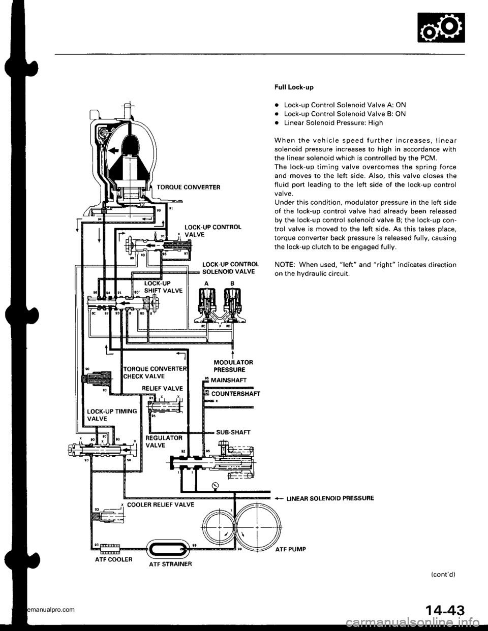
Full Lock-up
. Lock-up Control Solenoid Valve A: ON
. Lock-up Control Solenoid Valve B: ON
. Linear Solenoid Pressure: High
When the vehicle speed further increases, linear
solenoid pressure increases to high in accordance with
the linear solenoid which is controlled by the PCM.
The lock up timing valve overcomes the spring force
and moves to the left side. Also, this valve closes the
fluid port leading to the left side of the lock-up control
valve.
Under this condition, modulator pressure in the left side
of the lock-up control valve had already been released
by the lock-up control solenoid valve B; the lock-up con-
trol valve is moved to the left side. As this takes place,
torque converter back pressure is released fully, causing
the lock-up clutch to be engaged fully.
NOTE: When used. "left" and "right" indicates direction
on the hydraulic circuit.
+ LINEAR SOLENOIO PRESSURE
(cont'd)
LOCK-UP CONTROLSOLENOID VALVE
MODULATORPRESSURE
MAINSHAFT
COUNTERSHAFT
SUB-SHAFT
RELIEF VALVE
LOCK.UP TIMINGVALVE
COOLER BELIEF VALVE
ATF STRAINERATF COOLER
ATF PUMP
14-43
www.emanualpro.com
Page 1203 of 1395

Power Distribution
Fuse-to-Gomponent(sl Index (numerical sequence)
Under-hood Fuse/Rolay Box:
41
43
44
46
47
48
49
50
52
Capacity
'100 A
40A
7.5 A
15 A
40A
7.5 A
30A
204
204
15 A
10A
40A
40A
204
20A
Capacity
40A
204
7.5 A
wiro ColorFuseCircuit(s) Prot€cted
A
lgnition switch (BAT)
lntegrated control unit
Ceiling lights
Spotlights
PGM-Fl main relay
Not used
No. 7, 8, 10, 11 fuse in the under-dash fuse/relay box
Audio unit
Clock {'98 - 00 models)
Data link connector ('98 - 00 models)
ECM (VBU) {'98 - 00 models: M/T)
Heater control panel
PCM (VBU) (A./T)
Combination light switch (via under-dash fuse/relay box)
No. 20, 33 fuse in the under-dash fuss/relay box
Not used
Rear window defogger (via relay)
Door lock control unit
Hatch glass opener solenoid
Keyless door lock control unit ('98 - 00 models)
Horn relay
Horns (via relay)
via brake switch:
ABS control unit
Brake lights
Cruise control unit
ECM ('98 - 00 models: M/T)
High mount brake iight
PCM (4./T)
Trailer lighting connector
Turn signal/hazard relay (via switch)
Option connector (+B)
No. 6 fuse in the under-dash fuse/relay box
Blower motor (via relay)
Condenser fan motor (via relay)
Ay'C compressor clutch (via relay)
Radiator fan motor (via relay)
Wire Color Circuitls) Protoct
53
54
50
WHT/BLK
WHT/RED
WHT/BLK
WHT/BLU
WHT/BLU
WHT
WHT/GRN
WHT/GRN
WHT/GRN
WHT/BLK
WHT/RED
BLU/WHT
WHT
RED
BLK/RED
Under-hood ABS Fuss/nehy Box:
Fusg
61WHT
WHT/GRN
BRN/YEL
ABS pump motor {via relay}
ABS control unit
ABS control unit
{cont'd)
23-43
www.emanualpro.com
Page 1204 of 1395

Power Distribution
Fuse
1
3
5
6
7
I
9
10
11
12
13
14
"^
RED/B LU
RED/GRN
WHT/BLK
RED/VVHT
YEUBLK
RED
GRN/BLK
BLU/BLK
YEVBLK
YEUGRN
RED
BLK/YE L
BLK/VVHT
17
7.5 A
7.5 A
BLVBLU
BLKA/EL
18
19
20
22
7.54
7.54
l0 A
10 A
YEUBLK
YEVRED
BLKAr'YHT
RED /VHT
RED/YE L
Fuse-to-Component(sl Index (numerical sequencel (cont'dl
Under-dash Fuse/Relay Box:
Capacity
10 A
10 A
10 A
10 A
20A
204
15A
204
204
7.5 A'15 A
7.5 A
7.5 A
Wire ColorCircuit{s) Protected
Not used
Not used
Rear window washer motor (via switch)
Rear window wiper control unit ('97 model)
Rear window wiper motor
Daytime running rights resister {Canada)
Right headlight {High beam}
Daytime running rights resister (Canada)
High beam indjcator light
Left headlight (High beam)
Rear accessory socket (via relay)
Left rear power window motor (via switch)
Right rear power window motor (via switch)
Distributor (ignition control module)
Front passenger's power window motor (via switch)
Driver's power window motor {via switch)
Power window master switch (power window control unit)
Turn signal/hazard relay (via switch)
PGM-FI main relay
SRS unit (VA)
Cruise control unit (via switch)
Cruise main switch indicator light
Alternator
Charging system light
ELD unit (USA)
EVAP bypass solenoid valve ('98 - 00 models)
EVAP control canister vent shut valve ('98 - 00 models)
EVAP purge control solenoid valve
Primary HO2S
Secondary H02S
VSS
ABS control unit
Option connector (lG2)
Ay'C compressor clutch relay
Blower motor high relay
Blower motor relay
Condenser fan relay
Heater control panel
Left power mirror actuators (via switch)
Mode control motor
Radiator fan relay
Recirculation control motor
Right power mirror actuators (via switch)
Daytime running lights control unit (Canada)
Back-up lights
Reverse relay (A"/T)
Daytime running lights control unit (Canada)
Right headlight (Low beam)
Left headlight (Low beam)
23-44
www.emanualpro.com