HONDA CR-V 1998 RD1-RD3 / 1.G User Guide
CR-V 1998 RD1-RD3 / 1.G
HONDA
HONDA
https://www.carmanualsonline.info/img/13/5778/w960_5778-0.png
HONDA CR-V 1998 RD1-RD3 / 1.G User Guide
Page 1284 of 1395
Power Door Locks
UNDER.HOOD FUSE/FELAY BOX
Circuit Diagram (With Keyless Entry System)
GN TION SW TCHUNDER DASHFUSE/RELAY BOXEATTEFY
@*n'
WHT/GFN
8
ITEYLES--lI TRANSMIT]ER ILr--------
. PASSENGENS DOOR SWITCHES. ]NTEGRATED CONTROL UNIT5
23-124
HORNRELAY
f7
II- GRY
FRONTCEILINGL GHT
Y_o*,,.,,,0-
HATCHGLASSOPENERSOLENO D
HATCH
OPENERswlTcH
f7
I
YEL
L
fIllBl
+BL(
I
G61lG63l
INTEGRATED ICoNTROL UN T I
,Y, I
F",'*-{
.,ufrro I
tl
rthg#,i."J L
T
8!?i"'[:lll',fffi)
BLK
I
I--
G401G402
YEL
8LK
I
G551
DRIVER'SDOOF LOCKswrTcH
UNLOCK
nrrenu @
LOCK
@
KEYLESSDOOs LOCKCONTROL UNIT
BLK
I
G551
--1
www.emanualpro.com
Page 1286 of 1395
Power Door Locks
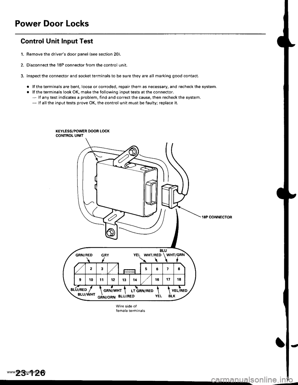
Gontrol Unit Input Test
1. Remove the driver's door panel (see section 20).
2. Disconnect the 18P connector from the control unit.
3. lnspect the connector and socket terminals to be sure they are all marking good contact.
. lf the terminals are bent, loose orcorroded, repairthem as necessary, and recheck the system.
. lf the terminals look OK, make the following input tests at the connector.- lf any test indicates a problem, find and correct the cause, then recheck the system.- lf all the input tests prove OK, the control unit must be faulty; replace it.
BLUGRN/BED GRY YEL WHT/REO WHT/GRN
723,/58
101t12 1131416171E
GRN/WHT I LT
18P CONNECTON
female terminals
23-126
www.emanualpro.com
Page 1288 of 1395
Power Door Locks
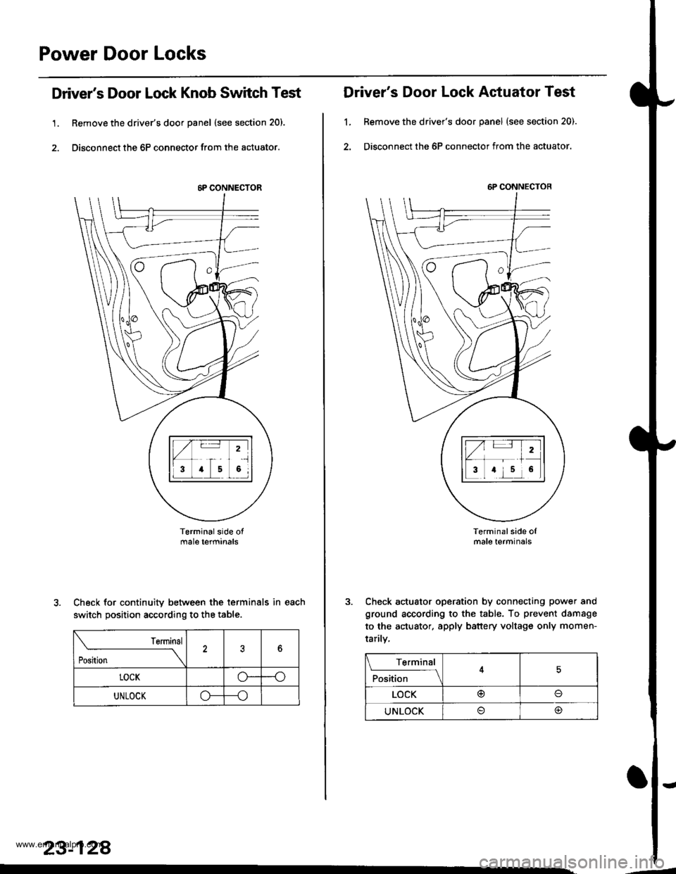
Driver's Door Lock Knob Switch Test
1. Remove the driver's door panel (see section 20).
2. Disconnect the 6P connector from the actuator.
Terminalside otmale terfiinals
Check for continuity between the terminals in each
switch position according to the table.
rsrmrnal
Position \
?6
LOCKo--o
UNLOCKo---o
23-128
.
6P CONNECTOR
Driver's Door Lock Actuator Test
1, Remove the driver's door panel (see section 20).
2. Disconnect the 6P connector from the actuator.
Terminal side ofmale terminals
Check actuator operation by connecting power and
ground according to the table. To prevent damsge
to the actuator. apply battery voltage only momen-
tarilv,
6P CONNECTOR
Terminal
F*'',1."
__l
LOCK@o
UNLOCK@
'-
www.emanualpro.com
Page 1290 of 1395

Power Door Locks
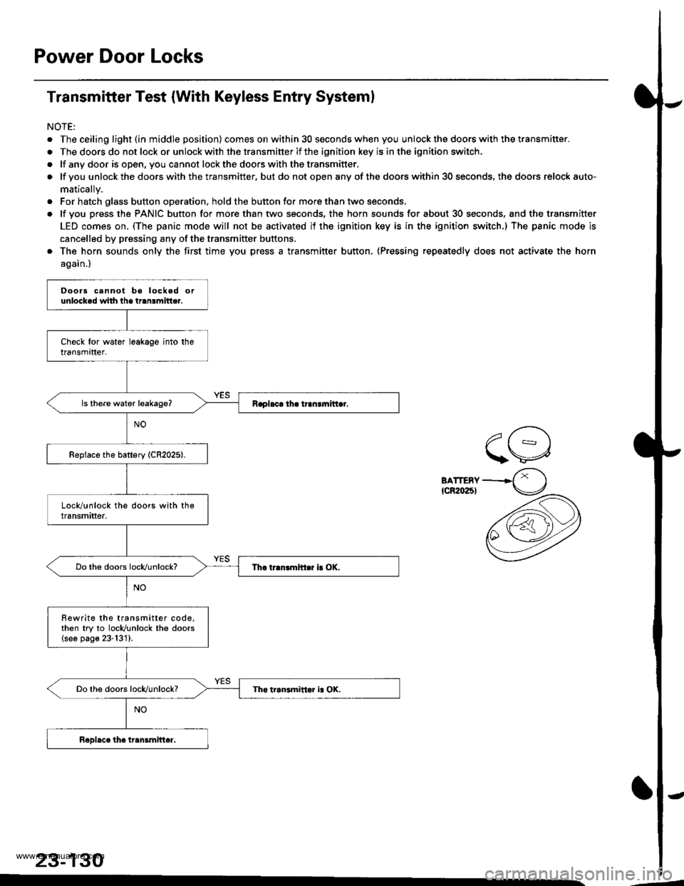
Transmitter Test (With Keyless Entry Systeml
NOTE:
. The ceiling light (in middle position) comes on within 30 seconds when you unlock the doors with the transmitter.
. The doors do not lock or unlock with the transmitter if the ignition key is in the ignition switch.
. lf any door is open, you cannot lockthe doorswith thetransmitter.
o lf you unlock the doors with the transmitter, but do not open any of the doors within 30 seconds, the doors relock auto-
matically.
. For hatch glass button operation, hold the button for more than two seconds.
. lf you press the PANIC button for more than two seconds, the horn sounds for about 30 seconds, and the transmitter
LED comes on. (The panic mode will not be activated if the ignition key is in the ignition switch.) The panic mode is
cancelled by pressing any of the transmitter buftons.
. The horn sounds only the first time you press a transmitter button, (Pressing repeatedly does not activate the horn
again.)
BATTERY{cR20251
23-130
Doors cannot bo locked orunlocked whh lhe transmitter.
Rewrite the transmitter code,then try to locldunlock the doors{see page 23-131}.
www.emanualpro.com
![HONDA CR-V 1998 RD1-RD3 / 1.G User Guide
Power Door Locks
UNDER.HOOD FUSE/FELAY BOX
Circuit Diagram (With Keyless Entry System)
GN TION SW TCHUNDER DASHFUSE/RELAY BOXEATTEFY
@*n
WHT/GFN
8
ITEYLES--lI TRANSMIT]ER ILr--------
. PASSENGENS DO HONDA CR-V 1998 RD1-RD3 / 1.G User Guide
Power Door Locks
UNDER.HOOD FUSE/FELAY BOX
Circuit Diagram (With Keyless Entry System)
GN TION SW TCHUNDER DASHFUSE/RELAY BOXEATTEFY
@*n
WHT/GFN
8
ITEYLES--lI TRANSMIT]ER ILr--------
. PASSENGENS DO](/img/13/5778/w960_5778-1283.png)


