ESP HONDA CR-V 1998 RD1-RD3 / 1.G User Guide
[x] Cancel search | Manufacturer: HONDA, Model Year: 1998, Model line: CR-V, Model: HONDA CR-V 1998 RD1-RD3 / 1.GPages: 1395, PDF Size: 35.62 MB
Page 521 of 1395
3rd Clutch
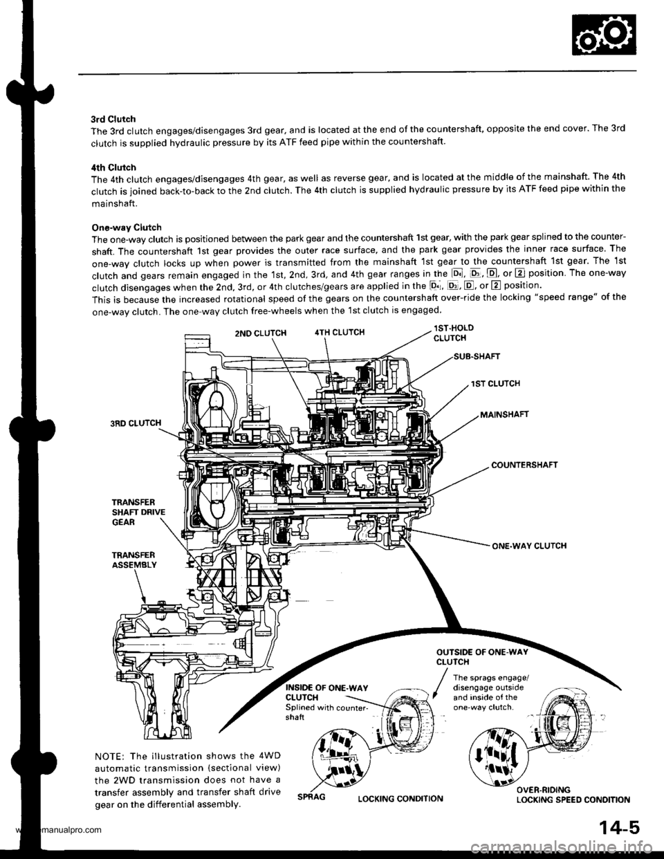
The 3rd clutch engages/disengages 3rd gear, and is located at the end of the countershaft, opposite the end cover. The 3rd
clutch is supplied hydraulic pressure by its ATF feed pipe within the countershaft.
ilth Clutch
The 4th clutch engages/disengages 4th gear, as well as reverse gear, and is located at the middle of the mainshaft. The 4th
clutch is joined back-to-back to the 2nd clutch. The 4th clutch is supplied hydraulic pressure by its ATF feed pipe within the
mainshaft.
One-way Clutch
The one-way clutch is positioned between the park gear and the countershaft 1st gear, with the park gear splined to the counter-
shaft. The countershaft 1st gear provides the outer race surface, and the park gear provides the inner race surface The
one,way clutch locks up when power is transmitted from the mainshaft lst gear to the countershaft 1st gear. The 1st
clutch and gears remain engaged in the 1st, 2nd, 3rd, and 4th gear ranges in the lo], pt, E, or E position The one-way
clutch disengages when the 2nd, 3rd, or 4th clutches/gears are applied in the lor, [d, E, or E position'
This is because the increased rotational speed of the gears on the countershaft over-ride the locking "speed range" of the
one-wav clutch. The one-wav clutch free-wheels when the lst clutch is engaged
lST.HOLDCLUTCH
1ST CLUTCH
MAINSHAFT3RD CLUTCH
COUNTERSHAFT
TRANSFERSHAFT DRIVEGEAR
TRANSFERASSEMBLY
NOTE: The illustration shows the 4WD
automatic transmission {sectional view)
the 2WD transmission does not have a
transfer assembly and transfer shaft drive
gear on the differential assembly.
2NO CLUTCH4TH CLUTCH
INSIDE OF ONE.WAYCLUTCH
ONE.WAY CLUTCH
OUTSIDE OF ONE.WAYCLUTCH
The sprags engage/disengage outsideand inside of theSplined with counter- -
shaft
OVER.RIOINGLOCKING SPEED CONOITIONLOCKING CONDITION
14-5,
www.emanualpro.com
Page 535 of 1395
![HONDA CR-V 1998 RD1-RD3 / 1.G User Guide
Ascending Control {37 Modol}
When the PCM determines that the vehicle is climbing a hill in E] and E positions, the system extends the engagement
area of 2nd g€ar and 3rd gear to prevent the transm HONDA CR-V 1998 RD1-RD3 / 1.G User Guide
Ascending Control {37 Modol}
When the PCM determines that the vehicle is climbing a hill in E] and E positions, the system extends the engagement
area of 2nd g€ar and 3rd gear to prevent the transm](/img/13/5778/w960_5778-534.png)
Ascending Control {37 Modol}
When the PCM determines that the vehicle is climbing a hill in E] and E positions, the system extends the engagement
area of 2nd g€ar and 3rd gear to prevent the transmission from frequently shifting between 2nd and 3rd gears, and
between 3rd and 4th gears, so the vehicle can run smooth and have more power when needed.
NOTE:
. Shift schedules stored in ths PCM between 2nd and 3rd gears, and between 3rd and 4th gears. enable the PCM's fuzzy
logic to automatically select the most suitable gear according to the magnitude of 8 gradient.
t Fuzzy logic is a form of artificial intslligence that lets computers respond to changing conditions much like a human
mind would.
3RD - tlTHASCENoING MODE: UFhift Sch.dulc
- . FLAT ROAD MODE
-----------. : GRADUAL ASCENDING MODE
- - - - - : STEEPASCENDING MODEo5l)
FFN1NS
7,.,.7a
: 2ND-3RD SHIFTING CHARACTERISTICSCONTROL AREA| 3RD-aTH SHIFTING CHARACTER|SnCSCONTROL AREA
62 mph
1100 km/h)Vehicle .o..d
Asconding Conirol ('98 - 00 Mod.ls)
When the PCM determines that the vohicle is climbing a hill in E] and E positions ('98 model), and in E] position ('99 -
00 models), the system extends the engagement srea of 2nd gear and 3rd gear to prevent the transmission from frequent-
ly shifting between 2nd and 3rd gears, and between 3rd and 4th gears, so the vehicle can run smooth and have more
power when needed.
NOTE: Shift schedulss stored in the PCM between 2nd and 3rd gears, and between 3rd and 4th gears, enable to selsct the
most suitable gear according to th6 magnitude of a gradi€nt.
ASCENDING MODE: Up.hift Sch.dul.
NN : 2ND-3RD SXImNG CHARACTERISTICS- GoNTRoLAREA
VVVVVZ:IRD-ITHSHIFnNGCHARACTERISTICS- cot{TRoL AREA
850
o
6:l mph11fl) km/hl
(cont'd)
2ND - 3RD
2ND + 3RD 3RD + 4TH
Vahicl. sDctd
14-19
www.emanualpro.com
Page 670 of 1395
Symptom-to-Component Chart
Hydraulic System (cont'd)
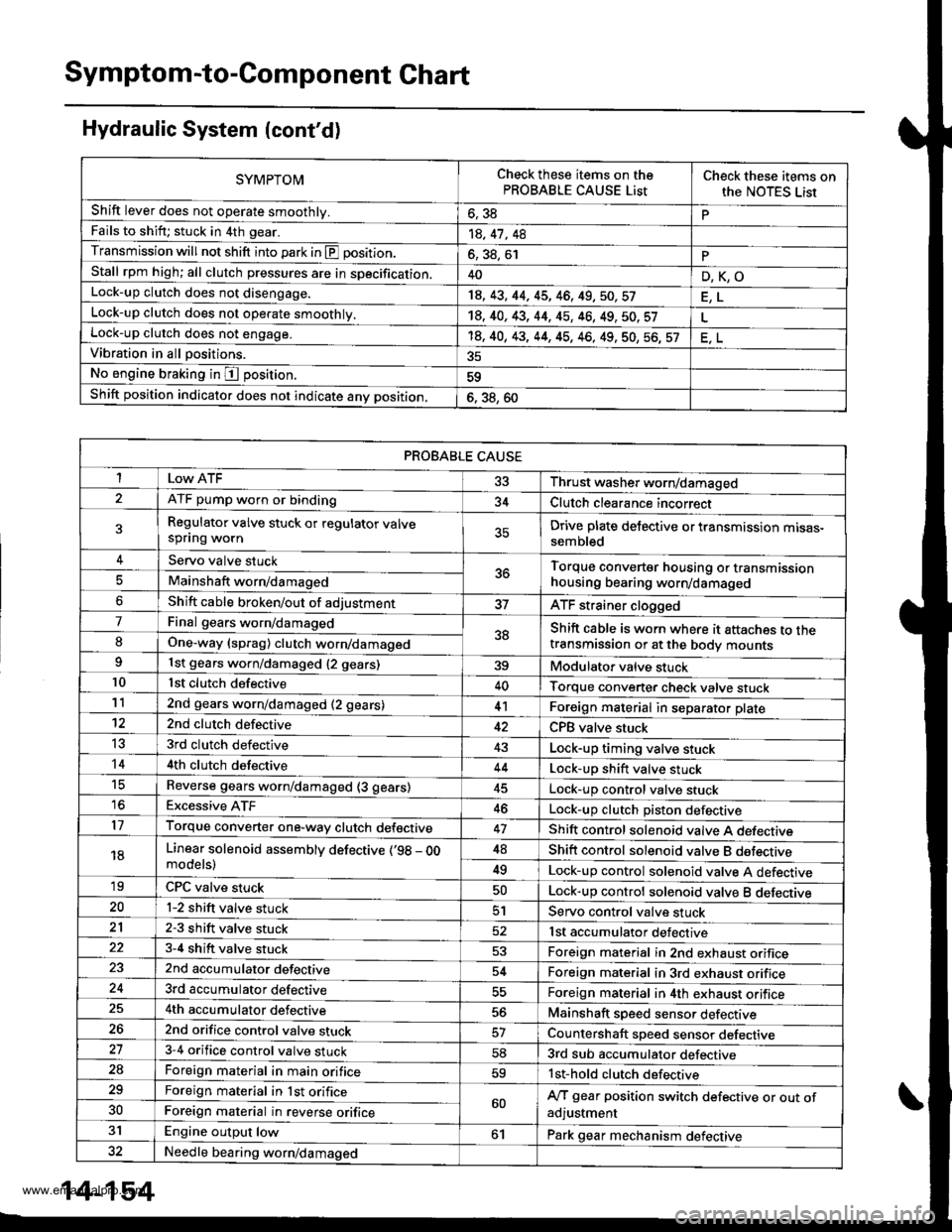
SYMPTOMCheck these items on thePROBABLE CAUSE ListCheck these items onthe NOTES Lisr
Shift lever does not operate smoothly.o, JdPFails to shift; stuck in 4th gear.14, 41 , 48
Transmission will not shift into park in E position.6, 38, 61PStall rpm high; all clutch pressures are in specification.40D,K,OLock-up clutch does not disengage.18, 43, 44, 45, 46, 49,50,57
Lock-up clutch does not operate smoothly.14, 40, 43, 44, 45, 46, 49, 50. 57Lock-up clutch does not engage.'t8, 40, 43, 44, 45, 46, 49, 50, 56, 57Vibration in all positions.
No engine braking in I position.59
Shift position indicator does not indicate anv position,6. 38, 60
PROBABLE CAUSE
I 33 Thrust washer worn/damaged
ATF pump worn or binding34Clutch clearance incorrect
Regulator valve stuck or regulator valvespflng wornDrive plate delective or transmission mtsas-sembled
Servo valve stuck5ttTorque converter housing or transmissionhousing bearing worn/damagedMainshaft worn/damaged
Shift cable broken/out of adjustmentATF strainer clogged
7Final gears worn/damaged38Shift cable is worn where it attaches to thetransmission or at the body mountsIOne-way (sprag) clutch worn/damaged
1st gears worn/damaged {2 gears)39Modulator valve stuck10lst clutch defective40Torque converter check valve stuck112nd gears worn/damaged (2 gears)41Foreign material in separator plate't22nd clutch defectiveCPB valve stuck
t53rd clutch defective43Lock-up timing valve stuck144th clutch defective44Lock-up shift valve stucktcReverse gears worn/damaged (3 gears)Lock-up control valve stuck16Excessive ATF46Lock-up clutch Diston defective17Torque converter one-way clutch defective47Shift control solenoid valve A defecttve
18Linear solenoid assemblv defective (,98 - OOmodels)48Shift control solenoid valve B dsfectrve
49Lock-up control solenoid valve A defective'19CPC valve stuckLock-up control solenoid valve B deleqtve20l-2 shift valve stuck51Servo control valve stuck212-3 shift valve stuck52lst accumulator defective3-4 shift valve stuck53Foreign material in 2nd exhaust orifice2nd accumulator defective54Foreign material in 3rd exhaust orifice3rd accumulator defectiveForeign material in 4th exhaust orifice4th accumulator defective56Mainshaft speed sensor defective262nd orifice control valve stuckCountershaft speed sensor defective273-4 orifice control valve stuck583rd sub accumulator defective2aForeign material in main orifice59lst-hold clutch defective29Foreign material in lst orifice60A/T gear position switch defective or out ofadjustment30Foreign material in reverse orifice
31Engine output low61Park gear mechanism defective32Needle bearing worn/damaged
14-154
www.emanualpro.com
Page 740 of 1395
Differential
Differential Carrier Replacement
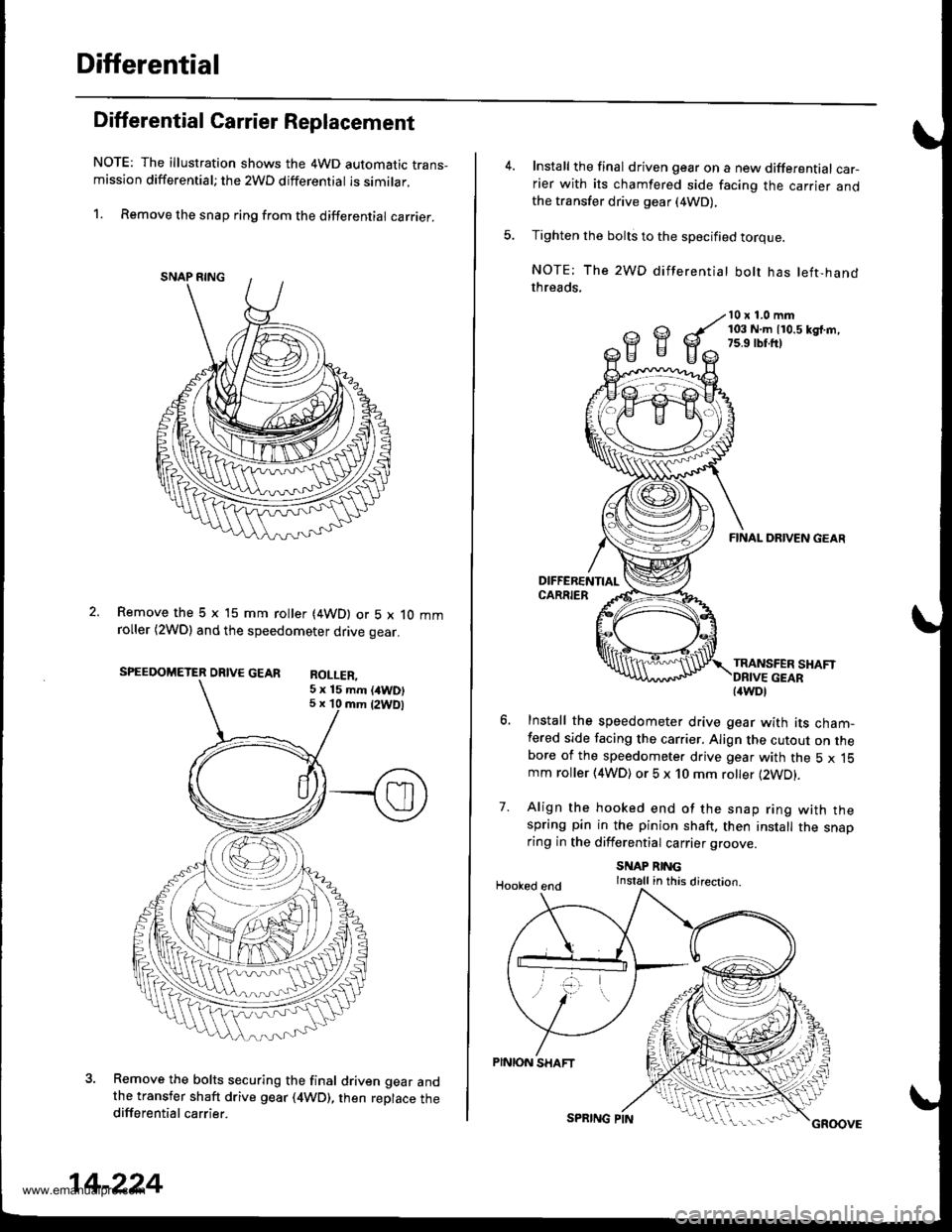
NOTE: The illustration shows the 4WD automatic trans-mission differential; the 2WD differential is similar.
1. Remove the snap ring from the differential carrier.
Remove the 5 x 15 mm roller (4WD) or 5 x 10 mmroller (2WDl and the speedometer drive gear.
SPEEDOMETER DRIVE GEAR RoI I FP
Remove the bolts securing the final driven gear andthe transfer shaft drive gear (4WD), then replace thedifferential carrier.
5 x 15 mm (/tWD)5 x 10 mm {2WDl
14-224
SPRING PINGROOVE
Install the final driven gear on a new differential car-rier with its chamfered side facing the carrier andthe transfer drive gear (4WD),
Tighten the bolts to the specified torque.
NOTE: The 2WD differentiat bolt has left-handthreads,
10 x 1.0 mm103 N.m 110.5 kd.m,7s.9 rbr.ft)
7.
FINAL DRIVEN GEAR
TRANSFER SHAFT
Install the speedometer drive gear with its cham-fered side facing the carrier. Align the cutout on thebore of the speedometer drive gear with the 5 x 15mm roller (4WD) or 5 x 10 mm roller (2WD).
Align the hooked end of the snap ring with thespring pin in the pinion shaft. then install the snaoring in the differential carrier groove
SNAP RINGInstall in this direction.Hooked end
PINION SHAFT
{4WDl
www.emanualpro.com
Page 868 of 1395
Power Steering Hoses, Lines
Fluid Leakage Inspection
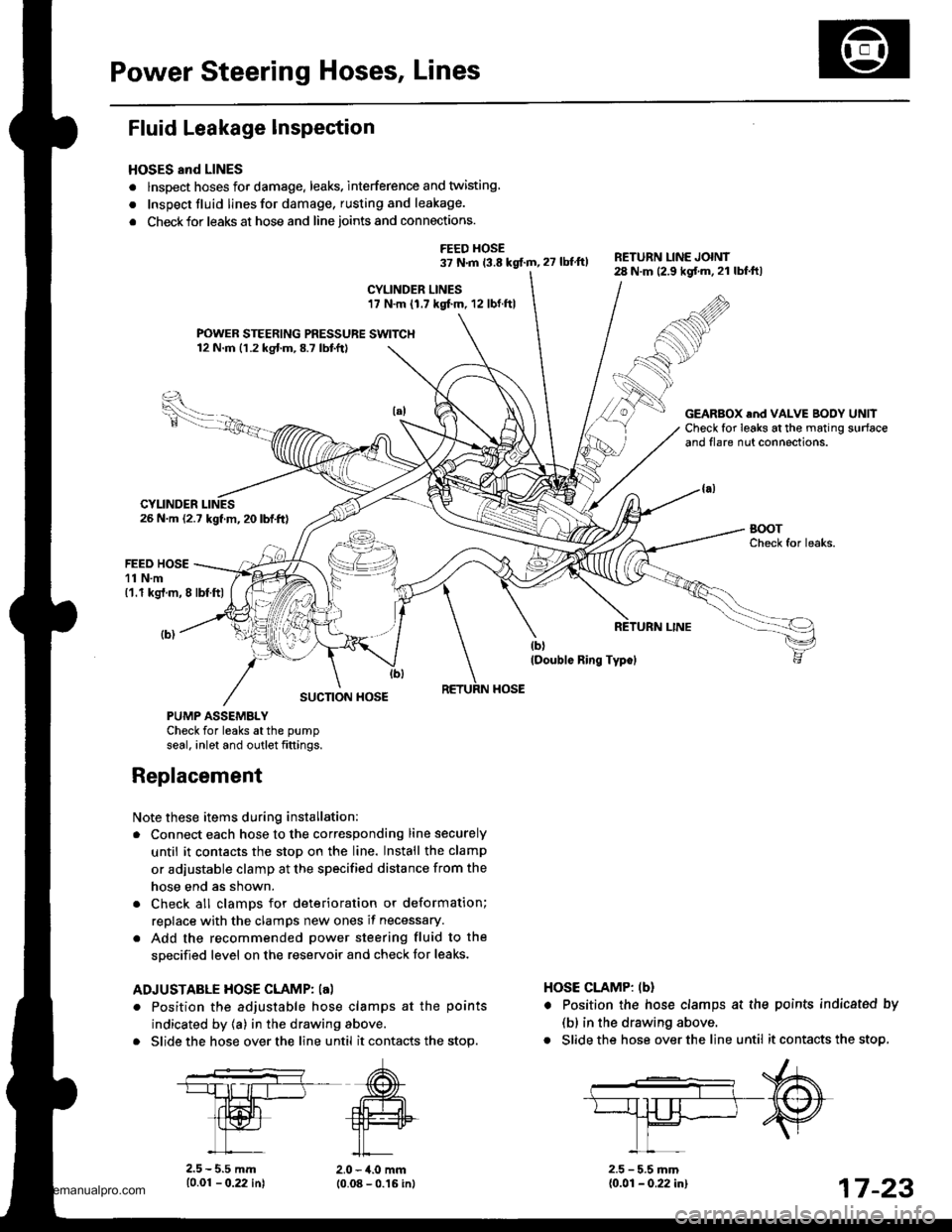
HOSES and LINES
. lnspect hoses for damage. leaks. interference and twisting
. Inspect fluid linesfor damage, rusting and leakage.
. Check for leaks at hose and line joints and connections.
FEED HOSE37 N.m 13.8 kgf.m, 27 lbtft)RETURN LINE JOINT28 N.m (2.9 kgf.m.21 lbf.ftl
CYLINDER LINES17 N.m (1.7 kgf.m. 12 lbf.ftl
FOWER STEERING PRESSURE SWITCH12 N.m (1.2 kgf.m,8.7 lbtft)
26 N.m (2.7 kgf.m, 20 lbf.ft)
GEARBOX .nd VALVE BODY UNllCheck for leaks at the mating surfaceand flare nut connections.
CYLINDER
FEED HOSE11 N.m('1.1 kgt.m, 8 lbf.ftl
SUCTION HOSE
PUMP ASSEMBLYCheck for leaks atthe pump
seal. inlet and outlet fittings.
Note these items during installation:
. Connect each hose to the corresponding line securely
until it contacts the stop on the line. Install the clamp
or adjustable clamp at the specified distance from the
hose end as shown.
. Check all clamDs for deterioration or deformation;
replace with the clamps new ones if necessary.
. Add the recommended power steering fluid to the
specified level on the reservoir and check for leaks.
ADJUSTABLE HOSE CLAMP: la)
. Position the adjustable hose clamps at the points
indicated by (a) in the drawing above.
. Slide the hose over the line until it contacts the stop.
HOSE CLAMP: lbl
. Position the hose clamps at the
(b) in the drawing above.
. Slide the hose over the line until
Replacement
10.01 - 0.22 in)
points indicatsd by
it contacts the stop,
2.0 - 4.0 mm10.08 - 0.16 inl2.5 - 5.5 mm{0.01 - 0.22 in}17 -23
www.emanualpro.com
Page 872 of 1395
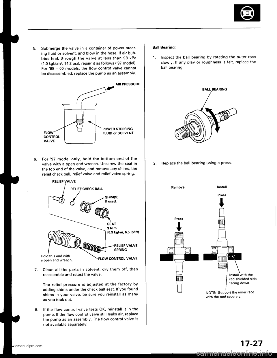
5. Submerge the valve in a container of power steer-
ing fluid or solvent, and blow in the hose. lf air bub-
bles leak through the valve at less than 98 kPa
(1.0 kgflcm'�, 14.2 psi), repair it as follows ('97 model).
For'98 - 00 models, the flow control valve cannot
be disassembled; replace the pump as an assembly
AIR PRESSURE
POWER STEENINGFLUID or SOLVENT
6.For'97 model only, hold the bottom end of the
valve with a open end wrench. Unscrew the seat in
the top end of the valve, and remove any shims, the
reliel check ball, relief valve and relief valve spring.
RELIEFALVE
RELIEF CHECK BALL
{w@r
7.
SEAT9 N.m(0.9 kgf.m, 6.5 lbfft)
RELIEF VALVESPRING
FLOW CONTBOL VALVE
Clean all the parts in solvent, dry them otf, then
reassemble and retest the valve.
The relief pressure is adjusted at the factory by
adding shims under the check ball seat lf you found
shims in your valve, be sure you reinstall as many
as you took out.
lf the flow control valve tests OK, reinstall it in the
pump. It the flow control valve still leaks air, replace
the pump as an assembly. The flow control valve is
not available separately.
8,
Hold this end witha open eno wrencn.
Ball Bearing:
'1. Inspect the ball bearing by rotating the outer race
slowly. lf any play or roughness is felt, replace the
ball bearing.
2. Replace the ball bearing using a press.
Removelnstall
Press
I
Press
I
lnstall with thered shaelded sidefacing down.
NOTEr SuPPort the inner race
with the tool securelY-
BALL EEARING
17-27
www.emanualpro.com
Page 887 of 1395
Power Steering Gearbox
13.
Reassembly (cont'd)
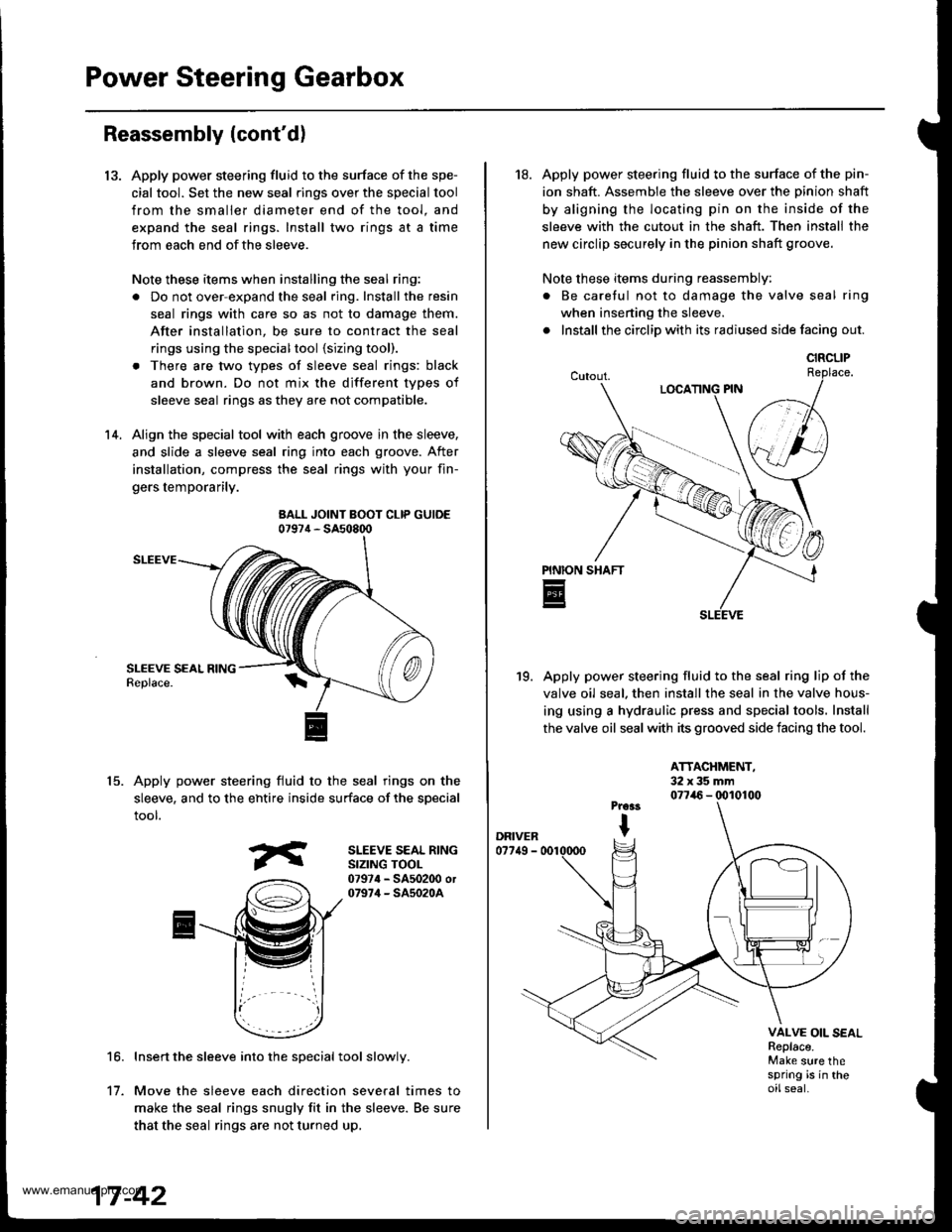
Apply power steering fluid to the surface of the spe-
cial tool. Set the new seal rings over the special tool
from the smaller diameter end of the tool. and
expand the seal rings. Install two rings at a time
Jrom each end ofthe sleeve.
Note these items when installing the seal ring:
. Do not over-expand the seal ring. Install the resin
seal rings with care so as not to damage them.
After installation, be sure to contract the seal
rings using the specialtool {sizing tool).
. There are two types of sleeve seal rings: black
and brown. Do not mix the different types of
sleeve seal rings as they are not compatible.
Align the special tool with each groove in the sleeve,
and slide a sleeve seal ring into each groove. After
installation, compress the seal rings with your fin-
gers temporarily.
BALL JOINT BOOT CLIP GUIDE07974 - SA508q)
SLEEVE
Apply power steering fluid to the seal rings on the
sleeve, and to the ehtire inside surface of the special
tool.
14.
15.
SLEEVE SEAL RINGSIZING TOOL07974 - SA502O0 or07974 - SA5020A
16.Insert the sleeve into the special tool slowly.
Move the sleeve each direction several times to
make the seal rings snugly fit in the sleeve. Be sure
that the seal rings are not turned up,
't1.
18. Apply power steering fluid to the surface of the pin-
ion shaft. Assemble the sleeve over the Dinion shaft
by aligning the locating pin on the inside of the
sleeve with the cutout in the shaft. Then install the
new circlip securely in the pinion shaft groove.
Note these items during reassembly:
. Be caretul not to damage the valve seal ring
when inserting the sleeve.
. Install the circlip with its radiused side facing out.
Apply power steering fluid to the seal ring lip of the
valve oil seal. then install the seal in the valve hous-
ing using a hydraulic press and special tools. Install
the valve oil seal with its grooved side facing the tool.
19.
ATTACHMENT,32x35mm077i16 - (x)10100
VALVE OIL SEALReplace.Make sure thespring is in theoilseal.
CIRCLIP
www.emanualpro.com
Page 889 of 1395
Power Steering Gearbox
Reassembly (cont'dl
Stecring Rack R8assembly
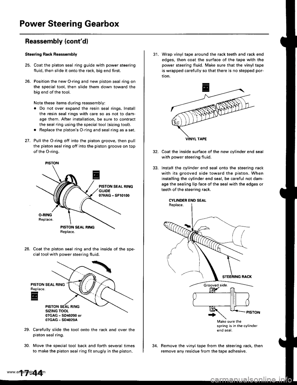
25. Coat the piston seal ring guide with power steering
fluid, then slide it onto the rack, big end first.
26. Position the new O-ring and new piston seal ring on
the sDecial tool, then slide them down toward the
big end of the tool.
Note these items during reassembly:
a Do not over expand the resin seal rings. Install
the resin seal rings with care so as not to dam-
age them. After installation, be sure to contract
the seal ring using the special tool (sizing tool).
a Replace the piston's O-ring and seal ring as a set.
27. Pull rhe O-ring off into the piston groove, then pull
the piston seal ring off into the piston groove on top
of the O-ring.
Coat the piston seal ring and the inside of the spe-
cial tool with power steering fluid.
07GAG - SO4O200 orOTGAG - SD'()2OA
Carefully slide the tool onto the rack and over thepiston seal ring.
Move the special tool back and fonh several times
to make the piston seal ring fit snugly in the piston.
24.
PISTONReplace
E
30.
PISTON
17-44
31. Wrap vinyl tape around the rack teeth and rack end
edges, then coat the surface of the tape with the
power steering fluid. Make sure that the vinyl tape
is wrapped carefully so that there is no stepped por-
tion.
Coat the inside surface of the new cvlinder end
with power steering fluid.
Install the cylinder end seal onto the steering rack
with its grooved side toward the piston. When
installing the cylinder end seal, be careful not dam-
age the sealing lip face of the seal with the edges or
teeth of the steering rack.
CYLINDER END SEAL
Make sure thespring is in lhe cylindereno seal
Remove the vinyl tape from the steering rack, then
remove any residue from the tape adhesive.
www.emanualpro.com
Page 891 of 1395
Power Steering Gearbox
Reassembly (cont'dl
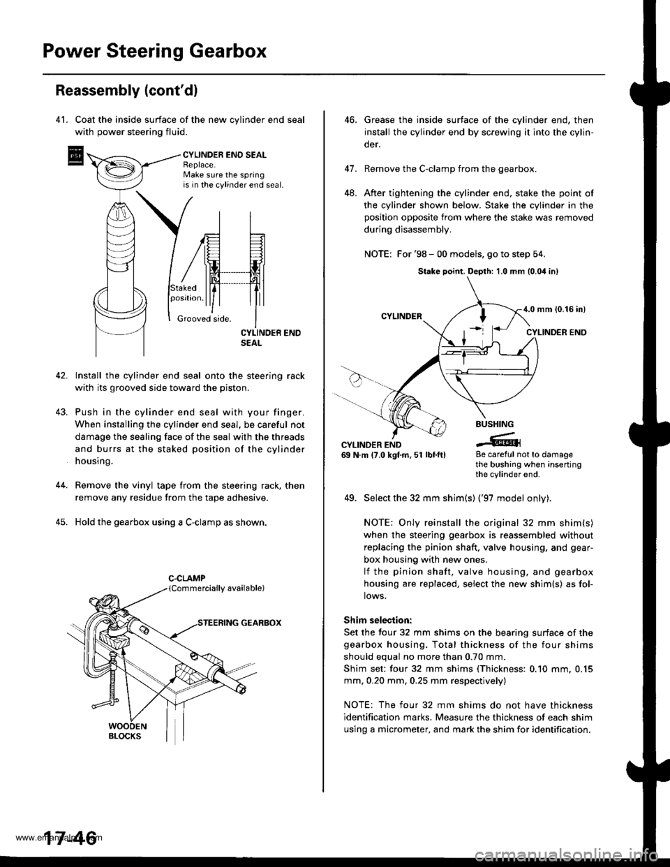
4l. Coat the inside surface of the new cvlinder end seal
with power steering fluid.
CYLINDEB ENO SEALReplace.Make sure the springis in the cylinder end seal.
43.
Stakedposrtron.
Grooved side.
42. Install the cylinder end seal onto the steering rack
with its grooved side toward the piston.
Push in the cylinder end seal with your finger.
When installing the cylinder end seal, be careful not
damage the sealing face of the seal with the threads
and burrs at the staked position of the cylinder
housing.
Remove the vinyl tape from the steering rack, then
remove any residue from the tape adhesive.
Hold the gearbox using a C-clamp as shown.
GEARBOX
44.
45.
C.CLAMP
17-46
46.Grease the inside surtace of the cylinder end, then
install the cylinder end by screwing it into the cylin-
der.
Remove the C-clamp from the gearbox.
After tightening the cylinder end, stake the point of
the cylinder shown below. Stake the cylinder in the
position opposite from where the stake was removed
during disassembly,
NOTE: For '98 - 00 models, go to step 54.
41.
48.
BUSHING
-tGCYLINDER END69 N.m (7.0 kgf.m,51 lbtft)8e careful not to damagethe bushing when insertingthe cylinder end.
49. Select the 32 mm shim(s) ('97 model onlv).
NOTE: Only reinstall the original 32 mm shim(s)
when the steering gearbox is reassembled without
replacing the pinion shaft. valve housing, and gear-
box housing with new ones.
lf the pinion shaft, valve housing, and gearbox
housing are replaced, select the new shim{s) as fol-
lows.
Shim selection:
Set the four 32 mm shims on the bearing surface of the
gearbox housing. Total thickness of the four shims
should equal no more than 0.70 mm.
Shim set: four 32 mm shims (Thickness: 0.10 mm, 0.15
mm, 0.20 mm, 0.25 mm respectively)
NOTE: The four 32 mm shims do not have thickness
identification marks. Measure the thickness of each shim
using a micrometer, and mark the shim for identification.
Stake point, Depth: 1,0 mm (0.04 inl
4.0 mm {0.16 in)
www.emanualpro.com
Page 907 of 1395
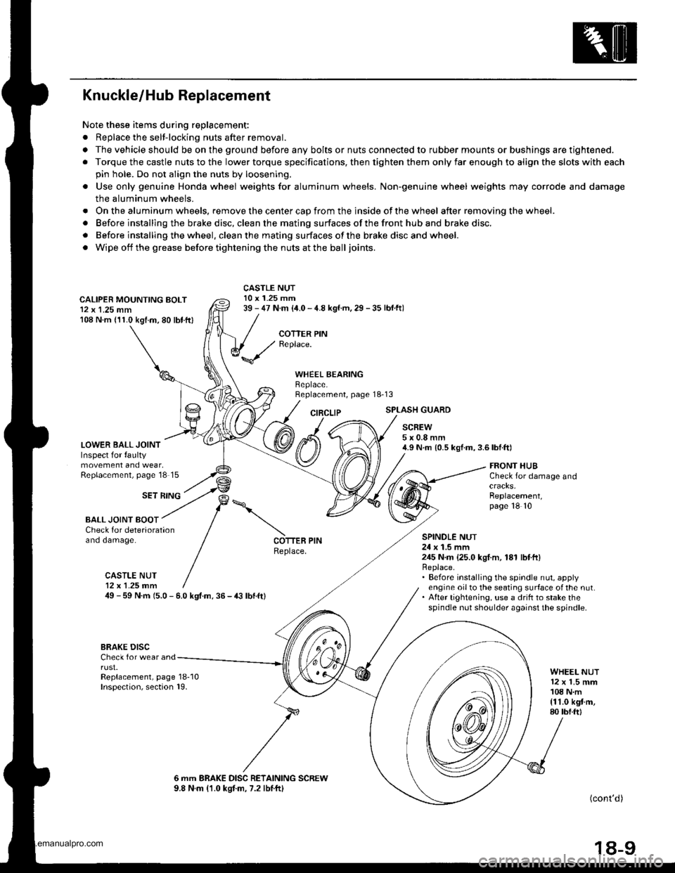
Knuckle/Hub Replacement
Note these items during replacement:
. Replace the selt-locking nuts after removal.
. The vehicle should be on the ground before any bolts or nuts connected to rubber mounts or bushings are tightened.
. Torque the castle nuts to the lower torque specifications, then tighten them only far enough to align the slots with each
pin hole. Do not align the nuts by loosening.
o Use only genuine Honda wheel weights for aluminum wheels. Non'genuine wheel weights may corrode and damage
the aluminum wheels.
. Onthealuminum wheels, remove the center cap from the inside of the wheel after removing the wheel.
. Before installing the brake disc, clean the mating surfaces of the front hub and brake disc.
. Before installing the wheel. clean the mating surfaces ofthe brake disc and wheel.
. Wipe off the grease before tightening the nuts at the balljoints.
CALIPER MOUNTING BOLT12 x 1.25 mm108 N.m (11.0 kgtm.80 lbt.ftl
LOWER BALL JOINTInspect for faultymovement and wear,Replacement, page'18 15
CASTLE NUT10 x 1.25 mm39 - 47 N.m (i1.0 - 4.8 kgf.m, 29 - 35 lbf.ftl
COTTER PINReplace.
WHEEL BEARINGBeplace.Replacement, page 18-13
CIRCLIPSPLASH GUARD
SCREW5x0.8mm4.9 N.m {0.5 kgf.m,3.6lbf.ft)
SET RING
FRONT HUBCheck for damage and
Replacement,page 18 10
BALL JOINT BOOTCheck for deteriorationano oamage.SPINOLE NUT24 x 1.5 mm245 N.m {25.0 kgI.m, 181 lbtft}Replace.. Before installing the spindle nut, applyengine oil to the seating surface of the nut.. After tightening, use a drift to stake thespindle nut shoulder against the spindle.
COTTER PINReplace.
CASTLE NUT12x 1.25 fim49 - 59 N.m 15.0 - 6.0 kgt.m. 36 - € lbf.ft)
BRAKE DISCCheck for wear andrust.Replacement, page 18-10Inspection, section 19.
WHEEL NUT12 x 1.5 mm108 N.m{11.0 kgt m,80 tbf.ftl
6 mm BRAKE DISC RETAINING SCREW9.8 N.m (1.0 kgtm, 7.2 lbtftl(cont'd )
18-9
www.emanualpro.com