Oil seal HONDA CR-V 1998 RD1-RD3 / 1.G User Guide
[x] Cancel search | Manufacturer: HONDA, Model Year: 1998, Model line: CR-V, Model: HONDA CR-V 1998 RD1-RD3 / 1.GPages: 1395, PDF Size: 35.62 MB
Page 165 of 1395
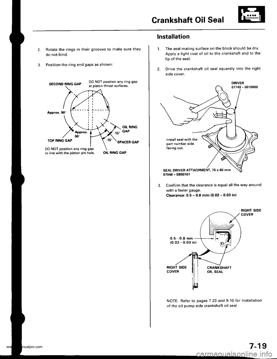
Crankshaft Oil Seal
Rotate the rings in their grooves to make sure they
do not bind.
Position the ring end gaps as shownl
SECOND RING GAP
Appror.90"
DO NOT position any ring gap
at piston thrust surfaces,
OIL RINGGAPAppror.90'TOP RI.IIG GAPSPACER GAP
DO NOT position any ring gap
in line with the piston pin hole.OIL RING GAP
1.
lnstallation
The seal mating surface on the block should be dry
Apply a light coat of oil to the crankshaft and to the
lip of the seal.
Drive the crankshaft oil seal squarely into the right
sroe cover.
DRIVER
lnstall seal with thepart number sidefacing out.
Confirm that the clearance is equal all the way around
with a feeler gauge.
Clearance:0.5 - 0.8 mm {0.02 - 0.03 inl
NOTE| Refer to pages 7 23 and 8-10 for installation
of the oil oumD side crankshait oil seal.
0.5-0.8 mm{O.02 0.03 in)
7-19
www.emanualpro.com
Page 168 of 1395
Crankshaft
12.
Installation (cont'd)
14.
13.
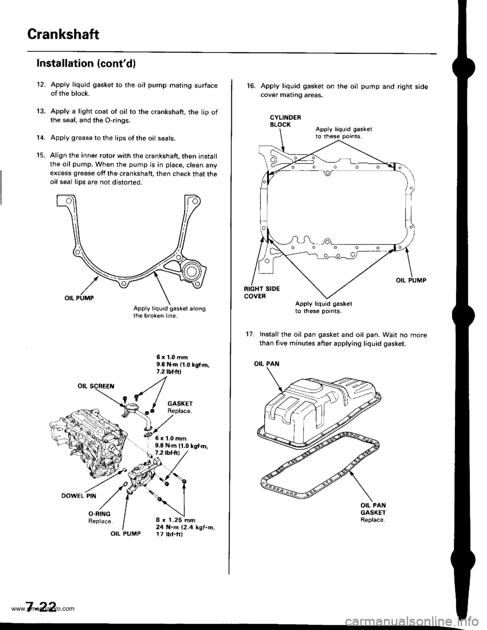
Apply liquid gasket to the oil pump mating surfaceof the block.
Apply a light coat of oil to the crankshaft, the lip ofthe seal, and the O-rings.
Apply grease to the lips of the oil seals.
Align the inner rotor with the crankshaft, then installthe oil pump. When the pump is in place, clean anyexcess grease off the crankshaft, then check that theoil seal lips are not distoned.
6x1,0mm9.8 N.m {1.0 kg{.m,,.2 tbf.ftl
I
{/^ I GASKET(..6 Replace."[z
O-RINGReplace.
OIL PUMP
6x1.0mm9,8 N.m 11.0 kg{.m,7.2lbt.trl
8 x 1.25 mm24 N.m {2.4 kgf.m,17 tbt.ftl
7 -22
,'t ./o,DowEL PtN
// |
16.Apply liquid gasket on
cover matrng areas.
CYLINDERBLOCK
the oil pump and right side
Apply liquid g€sketto these pornts.
17. Install the oil pan gasket and oil pan. Wait no
than five minutes after applying liquid gasket.
OIL PAN
OIL PANGASKETReplace.
Apply liquid gasketto these pornts,
www.emanualpro.com
Page 169 of 1395
Oil Seals
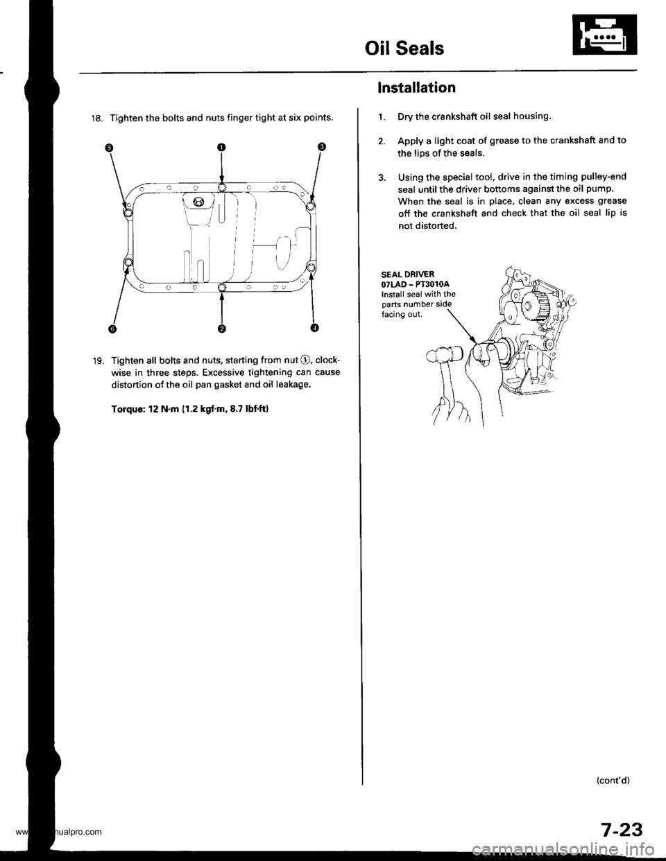
18. Tighten the bolts and nuts finger tight at six points.
Tighten all bolts and nuts, starting from nut O. clock-
wise in three steps. Excessive tightening can cause
distortion ot the oil pan gasket and oil leakage.
Torque: 12 N.m (1.2 kgt.m,8.7 lbtft)
19.
1.
lnstallation
Dry the crankshaft oil seal housing.
Apply a light coat of grease to the crankshsft and to
the lips of the seals.
Using the special tool, drive in the timing pulley-end
seal until the driver bottoms against the oil pump.
When the seal is in place, clean any excess grease
off the crankshaft and check that the oil seal lip is
not distorted,
SEAL DRIVEROTLAD - PT3O1OAlnstall sealwith theparts number sidefacing out.
(cont'd)
7-23
www.emanualpro.com
Page 170 of 1395
Oil Seals
Installation (cont'dl
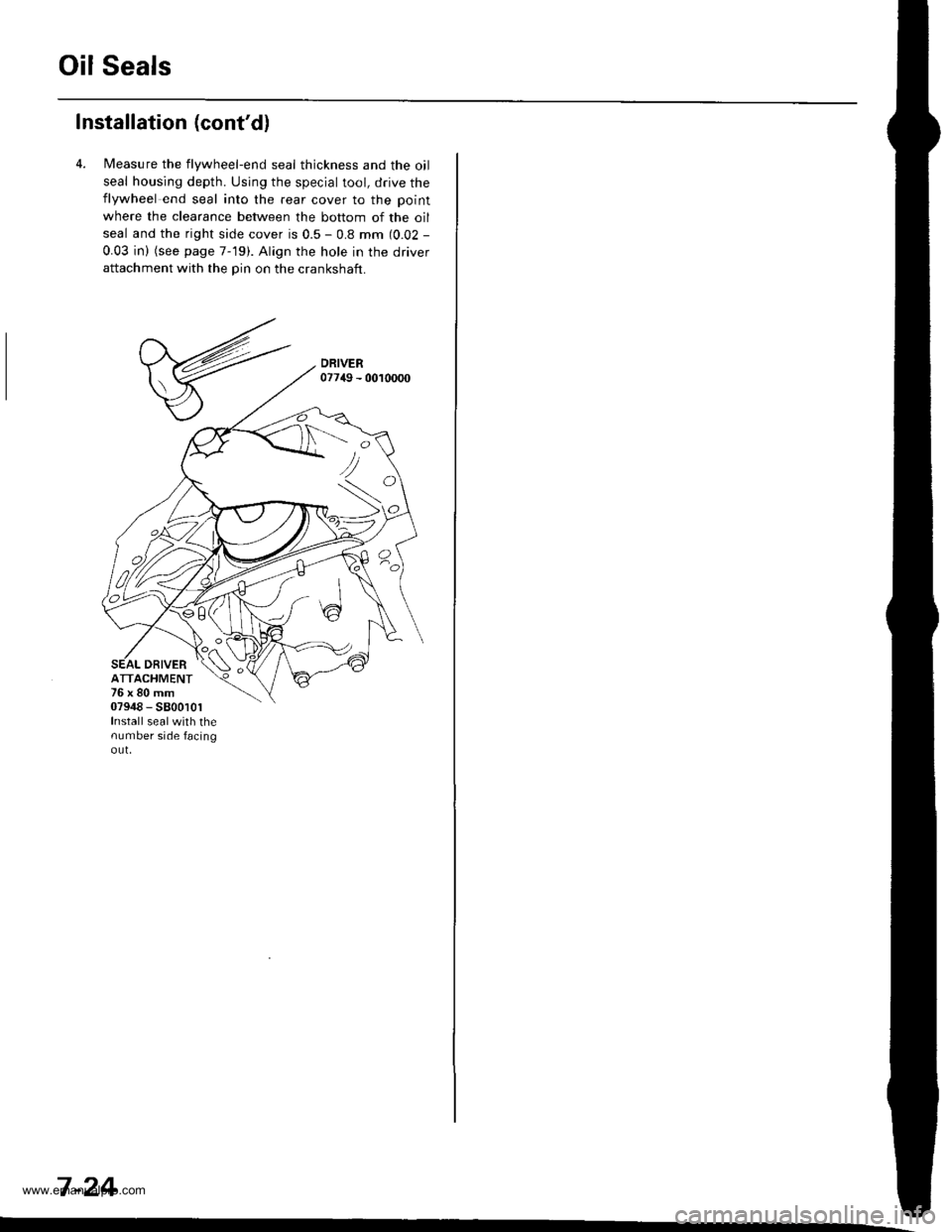
4. l/easure the flywheel-end seal thickness and the oil
seal housing depth. Using the special tool, drive theflywheel end seal into the rear cover to the point
where the clearance between the bottom of the oil
seal and the right side cover is 0.5 - 0.8 mm (0.02 -
0.03 in) (see page 7-19). Align the hole in the driverattachment with the pin on the crankshaft.
DRIVERATTACHMENT76x80mm07948 - 5800101Install sealwith thenumber side facingout,
<:
7 -24
www.emanualpro.com
Page 172 of 1395
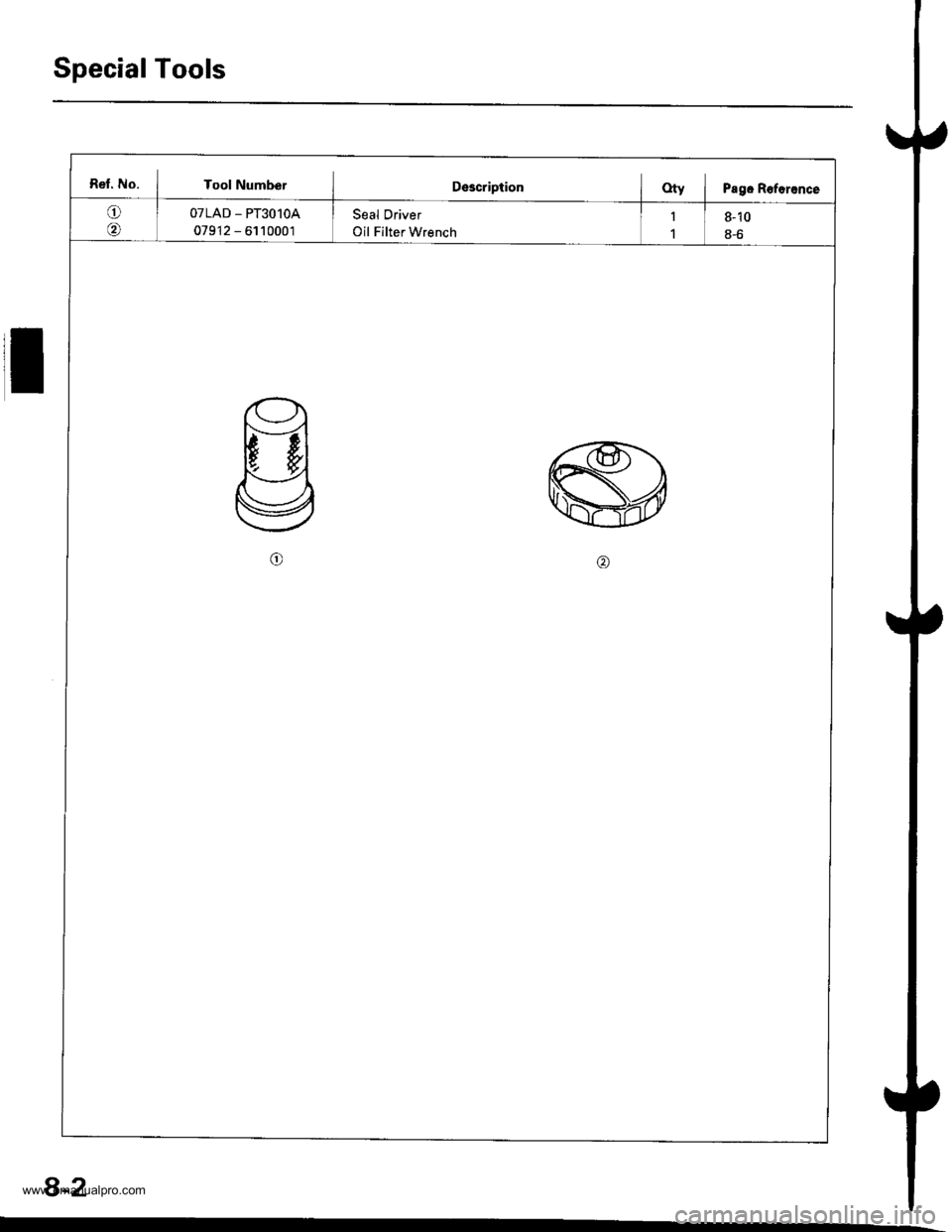
Special Tools
Ret. No. I Tool NumberIDescriptionOty i Pagc Roforance
oOTLAD _ PT3O1OA
079'12 - 6110001
Seal Driver
Oil Filter Wrench
1
1
8-10
8-6
8-2
www.emanualpro.com
Page 173 of 1395
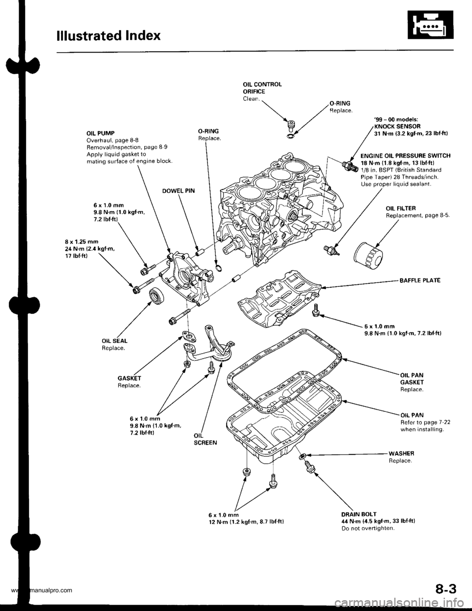
lllustrated Index
OIL CONTROLORIFICE
OIL PUMPOverhaul, page 8-8Removal/lnspection, page 8 IApply liquid gasket tomating surface of engine block.
'99 - 00 models:KNOCK SENSOR31 N.m {3.2 kgf.m.23 lbl.ft)
ENGINE OIL PRESSURE SWITCH18 N.m {1.8 kgtm, 13lbl.ft)1/8 in. BSPT (British StandardPipe Taper) 28 Threads/inch.Use proper liquid sealant.
O-RING
DOWEL PIN
6x1.0mm9.8 N.m (1.0 kgf.m,7.2 tbl.ft)
8 x 1.25 mm24 N.m 12.4 kgf.m,17 tbf.ft)
BAFFLE PLATE
kgtm,7.2 lbtftl
Replace.
6x1.0mm9.8 N.m 11.0 kgf m,7.2 tbf.ftl
OIL PANGASKETReplace.
OIL PANBeferto page 7 22when installing.
6x1.0mm12 N.m 11.2 kglm,8.7 lblftl
WASHEBReplace.
DRAIN BOLT4,1N.m {,1.5 kgf'm,33 lbf ft)Do not overtighten.
'-- /o-RrNG ,/ Reptace.
\^ ./
v,/
U
6x1.0mm9.8 N.rn {1.0
SCREEN
8-3
www.emanualpro.com
Page 175 of 1395
Oil Filter
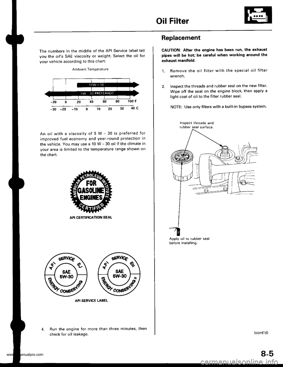
The numbers in the middle of the API Service label tell
you the oil's SAE viscosity or weighl. Select the oil for
your vehicle according to this chart:
Ambient Temperature
100 F
40c-30 -20 -10
An oil with a viscosity of 5 W - 30 is preferred for
improved fuel economy and year-round protection in
the vehicle. You may use a 10 W - 30 oil if the climate in
your area is limited to the temperature range shown on
the chart.
API SERVICE LABEL
Run the engine tor more than
check for oil leakage.
4.three minutes, then
Replacement
CAUTION: After the engine has been tun, ths exhaust
pipes will be hot; be carelul when working around the
exhaust manitold.
1. Remove the oil filter with the special oil filter
wrench.
lnsoect the threads and rubber seal on the new filter.
Wipe off the seat on the engine block, then apply a
light coat of oil to the filter rubber seal.
NOTE: Use only filters with a built-in bypass system.
oil to rubber sealinstalling.
-G
Derore
(cont'd)
8-5
Inspect threads and
www.emanualpro.com
Page 176 of 1395
Oil Filter
Replacement (cont'd)
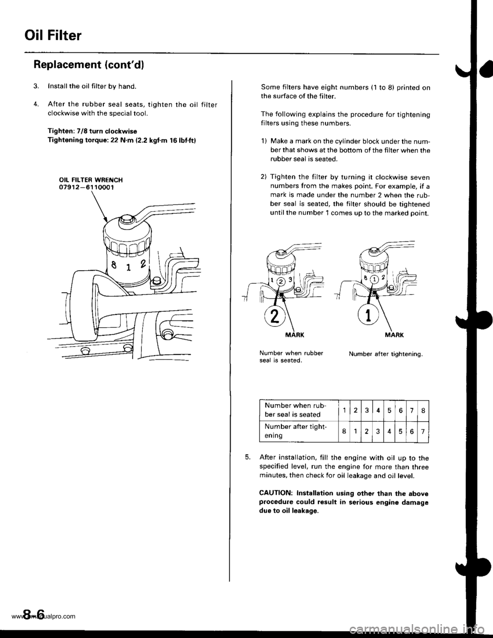
Installthe oil filter by hand.
After the rubber seal seats, tighten rhe oil filter
clockwise with the special tool.
Tighten: 7/8 turn clockwise
Tightening torque:22 N.m (2.2 kgt'm 16lbt.ft)
OIL FILTER WRENCH07912-61 10001
8-6
Some filters have eight numbers (1 to 8) printed on
the surface of the filter.
The following explains the procedure for tightening
filters using these numbers.
l) Make a mark on the cylinder block under the num-
ber that shows at the bottom of the filter when the
rubber seal is seated.
2) Tighten the filter by turning it clockwise seven
numbers from the makes point. For example, if a
mark is made under the number 2 when the rub-
ber seal is seated, the filter should be tightened
until the number 1 comes up to the marked point.
Number when rubberseal is seated.Number af ter tightening.
5.After installation. fill the engine with oil up to the
specified level, run the engine for more than threeminutes, then check for oil leakage and oil level.
GAUTION: Installation using other than the aboveprocedure could result in serious engine damage
due to oil leakage.
MARK
Number when rub-
ber seal is seated567IJ
Number after tight-
ening8123467
www.emanualpro.com
Page 177 of 1395
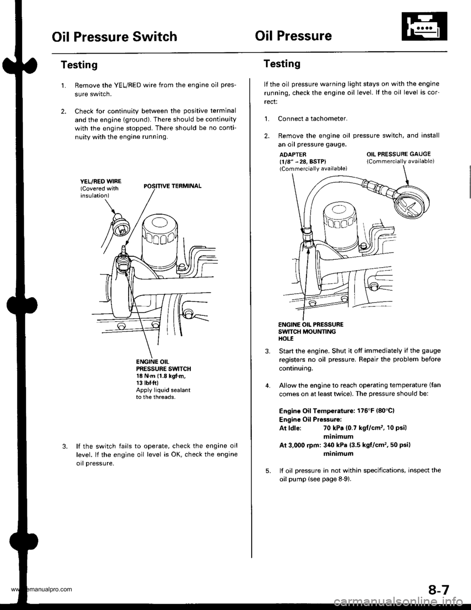
Oil Pressure SwitchOil Pressure
Testing
Remove the YEL/RED wire from the engine oil pres-
sure swrtcn.
Check for continuity between the positive terminal
and the engine {ground). There should be continuity
with the engine stopped. There should be no conti-
nuity with the engine running.
L
PRESSURE SWTCH18 N.m {1.8 kgf.m,13 tbr.ftlApply liquid sealantto the threads,
lf the switch fails
level. lf the engine
orl pressure.
to operate, check the engine oil
oil level is OK, check the engine
Testing
lf the oil pressure warning light stays on with the engine
running, check the engine oil level. lf the oil level is cor-
rect:
L Connect a tachometer.
2. Remove the engine oil
an oil pressure gauge.
ADAPTER(1/8" - 28, BSTP)(Commercially available)
pressure switch. and install
OIL PRESSURE GAUGE
{Commercially available)
4.
ENGINE OIL PRESSURESWTTCH MOUNNNGHOt-E
Start the engine. Shut it off immedjately if the gauge
registers no oil pressure. Repair the problem before
continuing.
Allow the engine to reach operating temperature (fan
comes on at least twice). The pressure should be:
Engino Oil Temperature: 176'F (80'C)
Engine Oil Pressure:
At ldle:70 kPa (0.7 kgt/cm'�, 10 psil
minimum
Ai 3,000 rpm: 3/r0 kPa {3.5 kgt/cm', 50 psi)
minimum
lf oil pressure in not within specifications, inspect the
oil pump (see page 8-9).
8-7
www.emanualpro.com
Page 180 of 1395
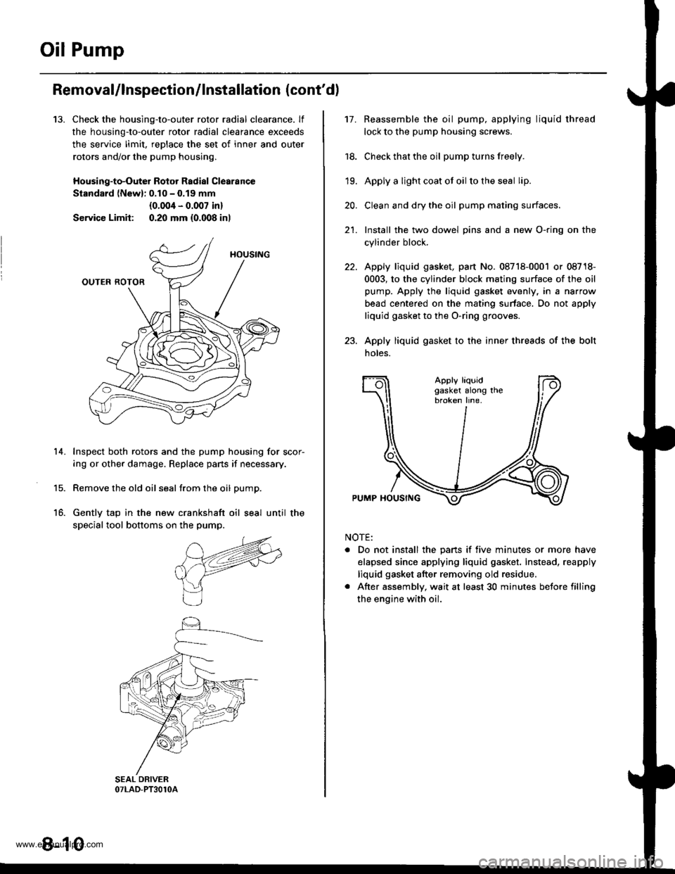
Oil Pump
13.
Removal/lnspection/lnstallation (cont'd)
Check the housing-to-outer rotor radial clearance. lf
the housing-to-outer rotor radial clearance exceeds
the service limit, reDlace the set of inner and outer
rotors and/or the pump housing,
Housing-to-Outer Rotor Radial Clearance
Standard lNewl: 0.10 - 0.19 mm
{0.004 - 0.007 in}
Service Limit: 0.20 mm {0.008 inl
Inspect both rotors and the pump housing for scor-
ing or other damage. Replace pans if necessary.
Remove the old oil seal from the oil pump.
Gently tap in the new crankshaft oil seal until the
special tool bottoms on the pump.
14.
15.
16.
8-10
17.Reassemble the oil pump, applying liquid thread
lock to the pump housing screws.
Check that the oil pump turns freely.
Apply a light coat ot oil to the seal lip.
Clean and dry the oil pump mating surfaces.
Install the two dowel pins and a new O-ring on the
cylinder block.
Apply liquid gasket, part No. 08718-0001 or 08718-
0003, to the cylinder block mating surface of the oil
pump. Apply the liquid gasket evenly, in a narrow
bead centered on the mating surface. Do not apply
liquid gasket to the O-ring grooves.
Apply liquid gasket to the inner threads of the bolt
noles.
18.
19.
20.
21.
Apply liquidgasket along thebroken line.
PUMP HOUSING
NOTE:
. Do not install the pans if five minutes or more have
elapsed since applying liquid gasket. Instead, reapply
liquid gasket after removing old residue.
. After assembly, wait at least 30 minutes betore filling
the engine with oil.
www.emanualpro.com