Valve clearance HONDA CR-V 1998 RD1-RD3 / 1.G User Guide
[x] Cancel search | Manufacturer: HONDA, Model Year: 1998, Model line: CR-V, Model: HONDA CR-V 1998 RD1-RD3 / 1.GPages: 1395, PDF Size: 35.62 MB
Page 327 of 1395
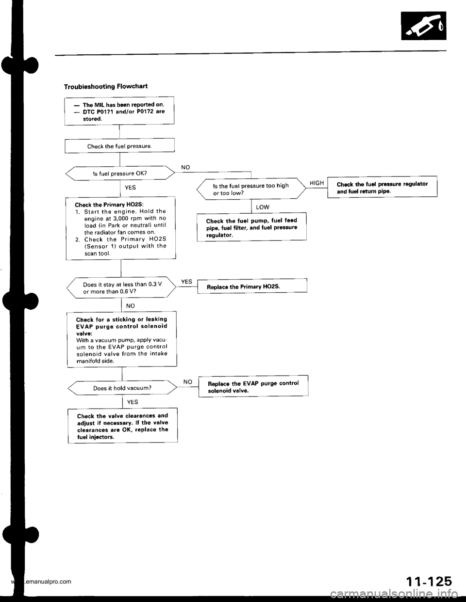
Troubleshooting Flowchart
- The MIL has been rePorted on- DTC P0171 andlot P0172 are
stored,
Check the lu6l pressuro regulator
and tusl relum PiPe.ls the lLrel pressure too high
Check lhe Primaty HO2S:1. Start the engine. Hold the
engine at 3,000 rpm with no
load (in Park ot neutral) until
the radiator fan comes on
2. Check the Primary HO2S(Sensor 1) outPut with the
scan tool.
Check lh€ fuel pumP. fuel faedpipe. fuel fiher, and luel Prossurc.eguhior.
Does it stay at lessthan 0.3 V
or more than 0.6 V?
Check for a sticking or leaking
EVAP purge control solenoid
With a vacuum pump, aPPIY vacu
um to the EVAP Purge control
solenoid valve from the intake
manifold side.
Does it hold vacuum?
Check th6 valve clearanc€s and
adjust il necessary. It the valv€
clearances are OK, replace the
fuel iniectors.
www.emanualpro.com
Page 328 of 1395
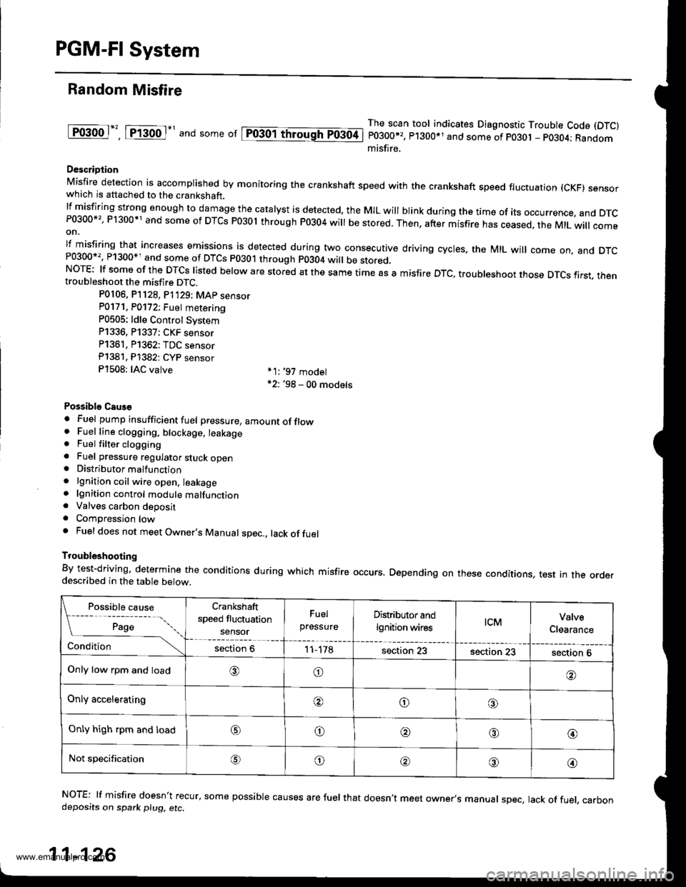
PGM-FI System
Random Misfire
lF()gool", tftod-' and some or lpiogol throughTo3oti
The scan tool indicates Diagnostic Trouble Code (DTC)
P0300*,, P1300*1 and some of po30t - pO3O4; Randommisfire.
Descriotion
Misfire detection is accomplished by monitoring the crankshaft speed with the crankshaft speed fluctuation (cKF) sensorwhich is attached to the crankshaft.lfmisfiring strong enough to damage the catalyst is detected, the MIL will blink during the time of its occurrence, and DTcP0300*'�, P1300*1 and some of DTCs P03ol through P0304 will be stored. Then, after misfire has ceased, the MtL will comeon,
lf misfiring that increases emissions is detected during two consecutive driving cycles, the MIL will come on, and DTcand some of DTCS p0301 through p0304 wi
be stored.NOTE: lf some of the DTCS listed below are stored at the same time as a misfire DTc, troubleshoot those DTcs first. thentroubleshoot the misfire DTC.
P0106, P]128, P1'129; MAp sensorP0171. P0172; Fuet metering
P0505: ldle Control Svstem
P1336, P1337; CKF sensor
P1361, P1362: TDC sensor
Pl381. Pl382: CYP sensor
P1508: IAC valve *1:,97 model*2: '98 - 00 models
Possiblo Caus€
. Fuel pump insufficient fuel pressure, amountofflow. Fuel line clogging. blockage, leakage. Fuel filter clogginga Fuel pressure regulator stuck open. Distributormalfunction
. lgnition coil wire open, leakage. lgnition control module malfunction. Valves carbon deposita Compression lowa Fuel does not meet Owner's Manual spec., lack offuel
Troubleshooting
By test-driving, determine the conditions during which misfire occurs. Depending on these conditions, test in the orderdescribed in the table below.
Possible cause
[ ;;;;- -....
Crankshaft
speed fluctuation
sensor
Fuel
pressureDistributor and
lgnition wirestcMValve
Clearance
Conditionsection 611-178section 23section 23section 6
Only low rpm and load,6)o
Only acceleratingooo
Only high rpm and loado@,a'@
Not specificationG\o@o@
NOTE: lf misfire doesn't recur, some possible causes are fuel that doesn't meet owner's manual spec, lack of fuel, carbondeposits on spark plu9, etc.
11-126
www.emanualpro.com
Page 329 of 1395
![HONDA CR-V 1998 RD1-RD3 / 1.G User Guide
Misfire Detected in One Cylinder
Ipffi1] Thescantoot indicates Diagnostic Trouble Code (DTC) P0301: Cylinder 1 misfire detected.
lF03O2l 16".""n toot indicates Diagnostic Trouble Code (DTC) P0302; Cy HONDA CR-V 1998 RD1-RD3 / 1.G User Guide
Misfire Detected in One Cylinder
Ipffi1] Thescantoot indicates Diagnostic Trouble Code (DTC) P0301: Cylinder 1 misfire detected.
lF03O2l 16".""n toot indicates Diagnostic Trouble Code (DTC) P0302; Cy](/img/13/5778/w960_5778-328.png)
Misfire Detected in One Cylinder
Ipffi1] Thescantoot indicates Diagnostic Trouble Code (DTC) P0301: Cylinder 1 misfire detected.
lF03O2l 16".""n toot indicates Diagnostic Trouble Code (DTC) P0302; Cylinder 2 misfire detected.
I P0303 | fne scan tool indicates Diagnostic Trouble Code (DTC) P0303: Cylinder3 misfire detected.
lF0il04l 16" ""un tool indicates Diagnostic Trouble Code (DTC) PO3O4: Cylinder 4 misfire detected
Description
Misfire detection is accomplished by monitoring the crankshaft speed with the crankshaft speed fluctuation (CKF) sensor
which is attached to the crankshaft.
lf misiiring strong enough to damage the catalyst is detected, the MIL will blink during the time of its occurrence. and DTC
P0301, P0302, P0303 and/or P0304 will be stored. Then, after the misfire has ceased, the MIL will come on.
lf misfiring that increases emissions is detected during two consecutive driving cycles. the MIL will come on, and DTc
P0301, P0302, P0303 and/or P0304 will be stored.
NOTE: lJ some of the DTcs listed below are stored at the same time as a misfire DTc, troubleshoot those DTcs first, then
troubleshoot the misfire DTC.
P0107, P0108, P'n2a, P1129t MAP sensor
Po'17 'l , P0112t Fuel suPP|Y system
P0441: EVAP insufficient Purge flow
P1336, P1337: CKF sensor
P1359, Pl361, P1362: TDC sensor
Pl381, P1382: CYP sensor
Possible Cause
. Fuel injector clogging, fuel leakage, air leakage
. Fuel injector circuit open or shorted
. Spark plug carbon deposits, fouling, malfunction
. lgnition wires open, leaking
. Distributor malfunction
. Compression low
. Valve clearance out of specification
(cont'd)
11-127
www.emanualpro.com
Page 397 of 1395
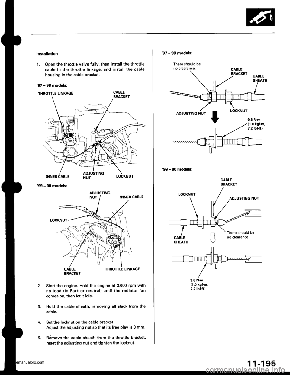
lnstellation
1. Open the throttle valve fully, then install the throttle
cable in the throttle linkage, and install the cable
housing in the cable bracket.
97 - 98 modols:
THRoTTLE LINKAGE CABLE
INNER CABLE
- (Xl modols:
LOCKNUT
'99
2.Sta.t the engine. Hold the engine at 3.000 rpm with
no load (in Park or neutral) until the radiator fan
comes on, then let it idle.
Hold the cable sheath, removing all slack from the
cable.
Set the locknut on the cable bracket.
Adiust the adjusting nut so that its free play is 0 mm.
Rimove the cable sheath from the throttle bracket,
reset the adjusting nut and tighten the locknut.
ADJUSTING
BRACKET
'97 - 98 modals:
lhere should beno clearance.
AD.'USTING NUT
'99 - 00 modeb:
CABLEBRACKET
9.8 N.ml'1.0 kgt'm,7.2 tbr.ft)
9.8 N.m(1.0 kg{.m,7.2lbllrl
www.emanualpro.com
Page 398 of 1395
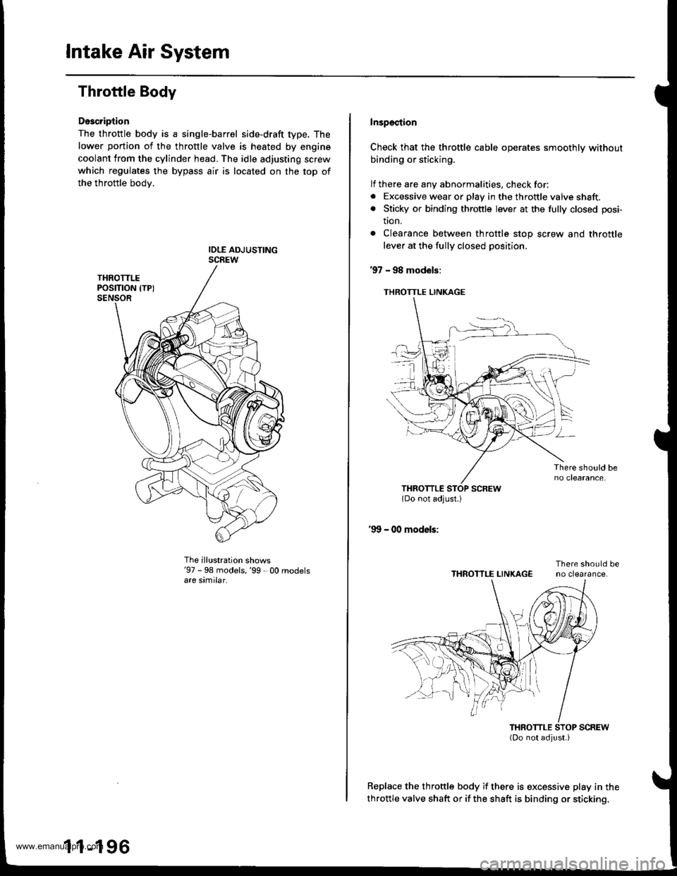
Intake Air System
Throttle Body
Doscription
The throttle body is a single-barrel side-draft type. The
lower portion of the throttle valve is heated by engine
coolant from the cylinder head. The idle adjusting screw
which regulates the bypass air is located on the top of
the throttle bodv.
The illustration shows'97 - 98 models,'99 - 00 rnodelsare similar.
1 1-196
lnspection
Check that the throttle cable operates smoothly without
binding or sticking.
lf there are any abnormalities, check for:. Excessive wear or play in the throftle valve shaft.. Sticky or binding throttle lever at the fully closed posi-
tton.
. Clearance between throttle stop screw and throttle
lever at the fully closed position.
97 - 98 models:
THROTTLE LINKAGE
Replace the throttle body if there is excessive play in the
throttle valve shaft or if the shaft is binding or sticking.
THROTTLE LINKAGE
www.emanualpro.com
Page 517 of 1395

Automatic Transmission
Special Tools . 14'2OescriptionGeneral Operation . .... 14 3Power Flow . . .. '14_6
Electronic Control System .. .. . . .. .14_15Hydraulic Control .. 14 24Hydraulic Flow....-....... .. . .... .. .. . 14_29Lock'up Syslem .. .'t4'39Electrical SystemComponenl Locdlrons 14 45
PCM Circuil Dragram (A/T Control Svstem)'97 Model ....................... . . .. - . ... .14-46'98Model ................. . ... .. .. .1450'99 00Models.... . .... . . . 1452
PCM Terminal Voltage/Measuring ConditionsA"/T Control System-'97Model ...... ..14'48A,/T Control System -'98 00 Models . . .. . . 14 54
Troubleshooting Procedures .. ..... ... - 14_56Svmotom to comoonent CharlEiectr,cal Syslem -'97 Model . . 14 60Electrical System -'98 - OO Models . .. . . 14_62Electrical Troubleshooting ('97 Model)Troubleshooting Flowaharts .... ..... . .. . . 14_64
Electrical Troubleshooting ('98 - 00 Models)Troubleshootinq Flowclt"n" .... . ....- . .14-93ElectricalTroublesliooting('99 00Models)Troubleshootino FlowchartO/D OFF Indicator Light Does Not Come On 14 131
O/D OFF Indicator Liaht On ConstantlY . . . .1!-132O/D OFF Indicator Light Does Not Come OnEven Though O/D Switch ls Pressed . .... - 14_133
Lock up Control Solenoid Valve A,/B AssemblyTest....................-......... . .14-135Replacement . .ll_135Shifr ControlSolenoid Valve Ay'B Assembl,Test .............................. . .. 14-136
Replacement..............- . .14'136Linear Solenoid AssemblYTest.............................................. .. .... . 14_137Replacement .. . 14138Marnshaftlcountershafl Speed SensorsReplacement ...-... 14_138A/T Gear Position SwitchTest ..........................-... . .. 14-139ReplacementA/T Gear Positionlndicator.................. 14-140
Valve Eodynepair ............................... ..... . . .. - . .. ... 14 192
Assembly .................... .. 1{_193
Valve CapsDesciiption....-........................ .. ...... 14194
tnspeition ................... .. 14' 195
N4ain Valve BodyDisassembly/lnspection/Reassemblv - ...... .. 14_196
Secondarv Valve BodYDisassemblv4nspectron/ReassemblY .. . 14 198
Reoulator Valve Bodvbisassembtv,lnspiction/Reassemblv . 14199
Servo EodvDisassembly/lnspection/Reassembly ... ....14'200
Lock'uo Valve BodYDis;ssembly/lnspection/Reassembly .... . 14_201
MainshaftDisassembly/lnspection/Reassembly .. .. .. ..14'202
Inspection ....-.............. ..11_203
Sealing RingsReilaceient ...... ..... . 14'204
CountershaftDisassembly/lnspection/Reassembly .. . . . . . 11-205
Disassembly/Reassemb|y . . ........ ...... . .. 14_206Inspedron ................ . .... . 14 207
One wav ClutchDisassembly/lnspection/ReassemblY ... 11_209
Sub-shaftDisassembly/lnspection/Reassembly ... . .. . 14-210
oisassembly/Re6ssembly . . ... .-...... . . ..14-211
Sub-shaft BearingsReplacement .......14'212
Clutchllfustrated Index .......... . . .14-213
Disassembly .... .. .....14-216Reassembfy .... . .. .. . 14'218
Differentialllfustrated Index " 14-222Backlash Inspection . .... . .14'223
Bearing Repiacement .. 11-223
Differe-ntial Carrier Replacement .. .. . . . .. ..11-2?4
OifSeal Replacement. . .. 14'225
Side Clearance lnspection . . - .. ... . - ...... . .. 11'226
Transmission Housing BearingsMainshaJVCountershaft EearingsRepfacement .......14221Sub'siralt Eearing Replacement . . . . . . . . . ..11'224
Toroue Converter Housing BearingsMainshattEearing/OilSe6lReplacement . .. l4229
Countershaft Bea;ing Replacement.. .... .. ..14-230
Input Test - '97 - 98 ModelsInput Test '99 - 00 Models
Symptom to-Component ChartHydraulic System ...............
Checking
Removal ...,lllustrated Index (4WD)
Interlock SystemInterlock ControlUnit lnputTest. -..... -.. .... . - 14 144* Key Interlock Solenoid Test .- .. . . . - . . . ..... 14_146* Shift Lock Solenoid Test ..............-.-. . .. . ... .... 14 147*Shift LockSolenoidReplacement...... .. . .. .. 14 148* park pin Switch Test ......... 14 119' Park Pin Switch Replacement- '97 - 98 Models ....... 14-150* Park Pin Swirch/Over Drive (O/Di SwitchReplacemenl '99-00Models . .. 14_151over-Drive (O/D) Switch {'99 00 [4odels]Test........_..................... .......14-152Hydr.ulic System
..............._............... t4 142.................................. 14-143
Control Lever AssemblyR6placement ......,.,Reverse ldler Gear
lllustrated lndex
.......... 14-230
14 231
11-231
1nsta1|ation ..................Park StopInspeclion/AdjustmenlTransfer AssemblY.......14.232
RoadTest.............-.... ........ .StallSpeedTest ....._........................ ....... 14-159Fluid Level......_................... 14'160
Disessembly .................... 14-235Transfer Drive Gear BearingReplacementTrans{er Driven Gesf Shaft BearingReplacementTransfer Housing Roller BearingReplacementTransfer Cov€r A Bearing Outer RaceReplacementTransfer Housing Bearing Outer RaceReplacement ......-..,,,,,.....ReassemblvTransmassaonBeassembly ... -.. .... .14 250
Torque Converier/Drive Plate . .-. .... .. . ... .....14_258
Transmissionlnstatlation .................. ....... 14'259
Cooler Flushing . . ......11-261ATF Cooler HosesConnection.................. ....... 14-266I Shift LeverRemoval/lnstallation . .. 14'261
Disassemblv/Reassemblv - '97 - 98 Models . . 14_264
Disassembli/Reassemblv -'99 - 00 Models . 14-269
Over'Orive (O/D) Switch WireClearanceAdjustment. - ... . . . .. .. . 14'270
Detent Spring Replscement . . -.. ... .14'271*Shift CableAdiustment ....... 14'272
Repfacement.............. . 11'273
14 15711-237
11-237
14-238
$-234
11-23914-240
Transmigrion
Inspeclron ....., ...........Transfer AssemblyRemova1,.,,,..............,lnstallalion ........... .. ...Transmission
14 164
14-16514,167
14-169
End Cover/Transmissio . 14'174Transmission Housing .... ... .. . . .... .. 14-176Torque Converter Housingly'alve Body.. - ... -. 14 178
lllustrated lndex (2WD)End Cover/Transmissio ....... 14 180Transmission Housing . . ... . .. .... ... 14'182Torque Convener Housing/r'alve Body ......- 14-184
End CovefRemovat ...................... ....... 14'186Transmission HousingRemoval ...................... .. 14_188Torque Convener HousingA/alve BodYRemovat ................-..... .-..... 14-190
www.emanualpro.com
Page 670 of 1395
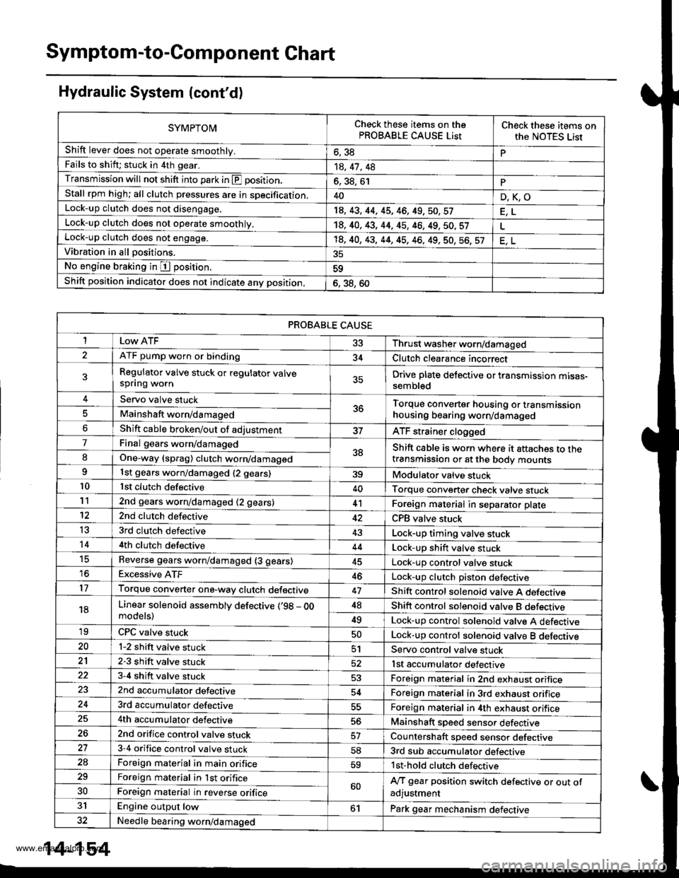
Symptom-to-Component Chart
Hydraulic System (cont'd)
SYMPTOMCheck these items on thePROBABLE CAUSE ListCheck these items onthe NOTES Lisr
Shift lever does not operate smoothly.o, JdPFails to shift; stuck in 4th gear.14, 41 , 48
Transmission will not shift into park in E position.6, 38, 61PStall rpm high; all clutch pressures are in specification.40D,K,OLock-up clutch does not disengage.18, 43, 44, 45, 46, 49,50,57
Lock-up clutch does not operate smoothly.14, 40, 43, 44, 45, 46, 49, 50. 57Lock-up clutch does not engage.'t8, 40, 43, 44, 45, 46, 49, 50, 56, 57Vibration in all positions.
No engine braking in I position.59
Shift position indicator does not indicate anv position,6. 38, 60
PROBABLE CAUSE
I 33 Thrust washer worn/damaged
ATF pump worn or binding34Clutch clearance incorrect
Regulator valve stuck or regulator valvespflng wornDrive plate delective or transmission mtsas-sembled
Servo valve stuck5ttTorque converter housing or transmissionhousing bearing worn/damagedMainshaft worn/damaged
Shift cable broken/out of adjustmentATF strainer clogged
7Final gears worn/damaged38Shift cable is worn where it attaches to thetransmission or at the body mountsIOne-way (sprag) clutch worn/damaged
1st gears worn/damaged {2 gears)39Modulator valve stuck10lst clutch defective40Torque converter check valve stuck112nd gears worn/damaged (2 gears)41Foreign material in separator plate't22nd clutch defectiveCPB valve stuck
t53rd clutch defective43Lock-up timing valve stuck144th clutch defective44Lock-up shift valve stucktcReverse gears worn/damaged (3 gears)Lock-up control valve stuck16Excessive ATF46Lock-up clutch Diston defective17Torque converter one-way clutch defective47Shift control solenoid valve A defecttve
18Linear solenoid assemblv defective (,98 - OOmodels)48Shift control solenoid valve B dsfectrve
49Lock-up control solenoid valve A defective'19CPC valve stuckLock-up control solenoid valve B deleqtve20l-2 shift valve stuck51Servo control valve stuck212-3 shift valve stuck52lst accumulator defective3-4 shift valve stuck53Foreign material in 2nd exhaust orifice2nd accumulator defective54Foreign material in 3rd exhaust orifice3rd accumulator defectiveForeign material in 4th exhaust orifice4th accumulator defective56Mainshaft speed sensor defective262nd orifice control valve stuckCountershaft speed sensor defective273-4 orifice control valve stuck583rd sub accumulator defective2aForeign material in main orifice59lst-hold clutch defective29Foreign material in lst orifice60A/T gear position switch defective or out ofadjustment30Foreign material in reverse orifice
31Engine output low61Park gear mechanism defective32Needle bearing worn/damaged
14-154
www.emanualpro.com
Page 671 of 1395
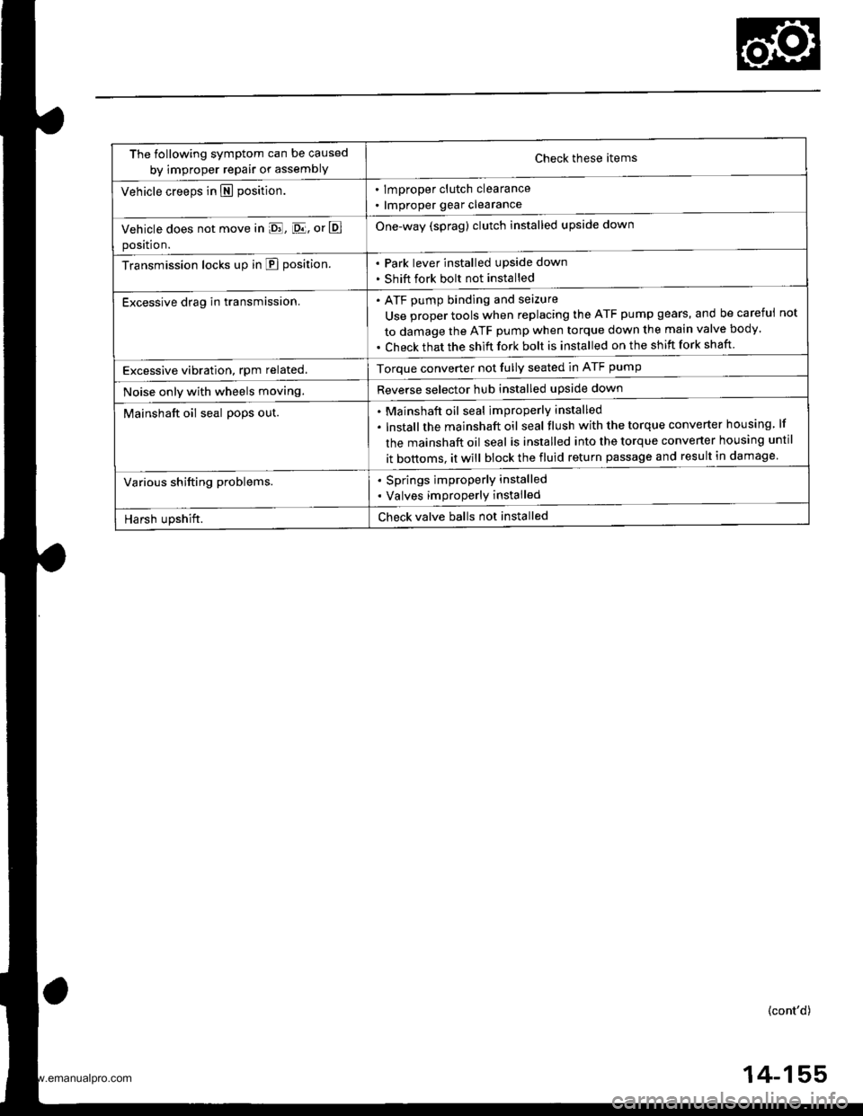
The following symptom can be caused
by improper repair or assemblYCheck these items
. lmproper clutch clearance
. lmproper gear clearance
One-way (sprag) clutch installed upside down
Park lever installed upside down
Shift fork bolt not installed
Vehicle creeps in N position.
Vehicle does not move in E, [D.lj, or E
position.
Transmission locks up in E position.
Excessive drag in transmission.ATF pump binding and seizure
Use proper tools when replacing the ATF pump gears, and be careful
to damage the ATF pump when torque down the main valve body.
Check that the shift fork bolt is installed on the shift fork shaft
not
Excessive vibration, rpm related.Torque converter not fully seated in ATF pump
Reverse selector hub installed upside downNoise only with wheels moving.
Mainshaft oil seal po9s out.Mainshaft oil seal improperly installed
lnstallthe mainshaft oil seal tlush with the torque converter housing lf
the mainshaft oil seal is installed into the torque converter housing until
it bottoms. it will block the fluid return passage and result in damage
Various shifting problems.. Springs improperly installed
. Valves improperly installed
Harsh upshift.Check valve balls not installed
(cont'd)
4-155
www.emanualpro.com
Page 711 of 1395
ATF Pump
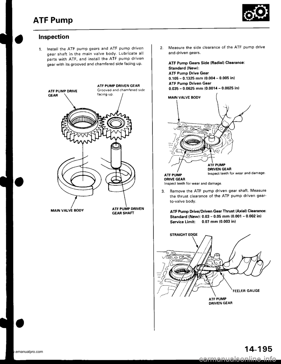
Inspection
1. Install the ATF pump gears and ATF pump driven
gear shaft in the main valve body Lubricate all
parts with ATF, and install the ATF pump driven
gear with its grooved and chamfered side facing up
MAIN VALVE AOOY
ATF PUMP ORIVE
2. Measure the side clearance of the ATF pump drive
and driven gears.
ATF Pump Gears Side {Radial} Cloarance:
Standard (Newl:
ATF Pump Drive Gear
0.105 - 0.1325 mm {0.004 - 0.005 in}
ATF Pumo Driven Gear
0.035 - 0.0625 mm {0.0014 - 0.0025 in)
MAIN VAI-VE BOOY
fl
L/
ATF PUMPDRIVE GEAR
ATF PUMPDRIVEN GEARInspecl teeth {or wear and damage
Inspect teeth for wear and damage,
3. Remove the ATF pump driven gear shaft Measure
the thrust clearance of the ATF pump driven gear-
to-valve body.
ATF Pumo Drive/Driven Gear Thrust (Axiall Clearance:
Standard (N€w): 0.03 - 0.05 mm {0'001 - 0 002 inl
Service Limit: 0.07 mm 10.003 in)
ATF PUMPORIVEN GEAR
14-195
www.emanualpro.com
Page 876 of 1395
Power Steering Gearbox
Removal
Note these items during removal:
. Using solvent and a brush, wash any oil and dirt off
the valve body unit its lines, and the end if the gear-
box. Blow dry with compressed air.
. Be sure to remove the steering wheel before discon-
necting the steering joint. Damage to the cable reel
can occur.
. With 4WD. tilt the engine with a jack to expand the
clearance between the transfer assembly and rear
beam when removing the steering gearbox from the
rear oeam.
Do not remove the steering gearbox by removing the
transfer assembly from the transmission.
1. Drain the power steering fluid as described on page'17-15.
Raise the vehicle, and suppon it on safety stands in
the proper locations (see section 1).
Remove the front wheels,
Remove the drive/s airbag assembly {see section 24).
Remove the steering wheel {see page 17-18).
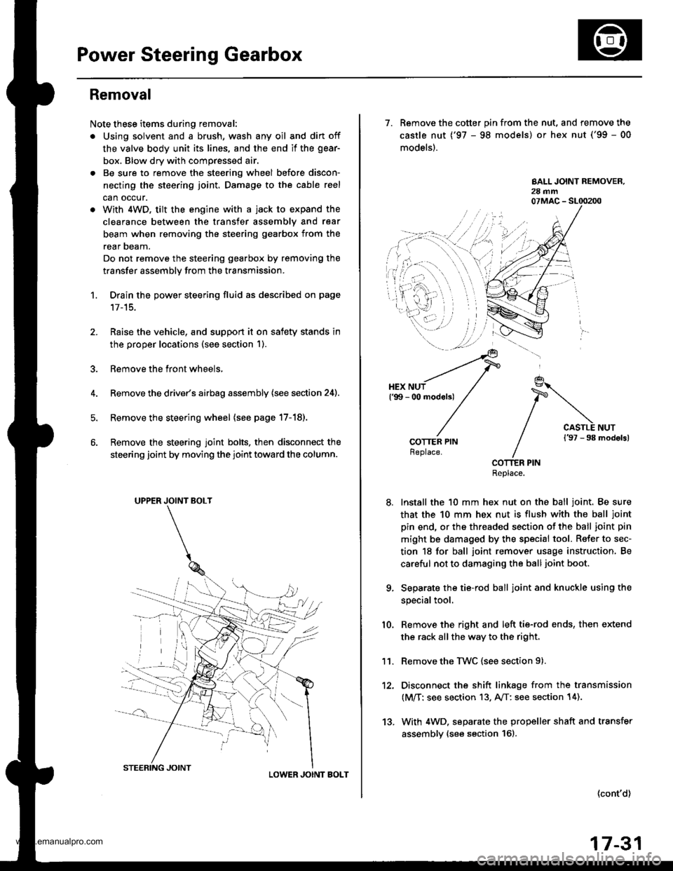
Remove the steering joint bolts, then disconnect the
steering joint by moving the joint toward the column.
UPPER JOINT BOLT
LOWER JOINT BOLT
13.
7. Remove the cotter pin from the nut, and remove the
castle nut {'97 - 98 models) or hex nut ('99 - 00
models).
COTTER PINReplace.
Install the 10 mm hex nut on the ball joint. Be sure
that the 10 mm hex nut is flush with the ball joint
pin end, or the threaded section of the ball joint pin
might be damaged by the special tool. Refer to sec-
tion 18 for ball joint remover usage instruction, Be
careful not to damaging the ball joint boot.
Separate the tie-rod ball joint and knuckle using the
special tool.
Remove the right and left tie-rod ends, then extend
the rack all the way to the right.
Remove the TWC (see section 9).
Disconnect the shift linkage from the transmission
(M/T: see section 13, A/T: see section 14).
With 4WD. separate the propeller shaft and transfer
assembly (see section 161.
10.
11.
(cont'd)
17-31
www.emanualpro.com