Valve cover HONDA CR-V 1998 RD1-RD3 / 1.G User Guide
[x] Cancel search | Manufacturer: HONDA, Model Year: 1998, Model line: CR-V, Model: HONDA CR-V 1998 RD1-RD3 / 1.GPages: 1395, PDF Size: 35.62 MB
Page 550 of 1395
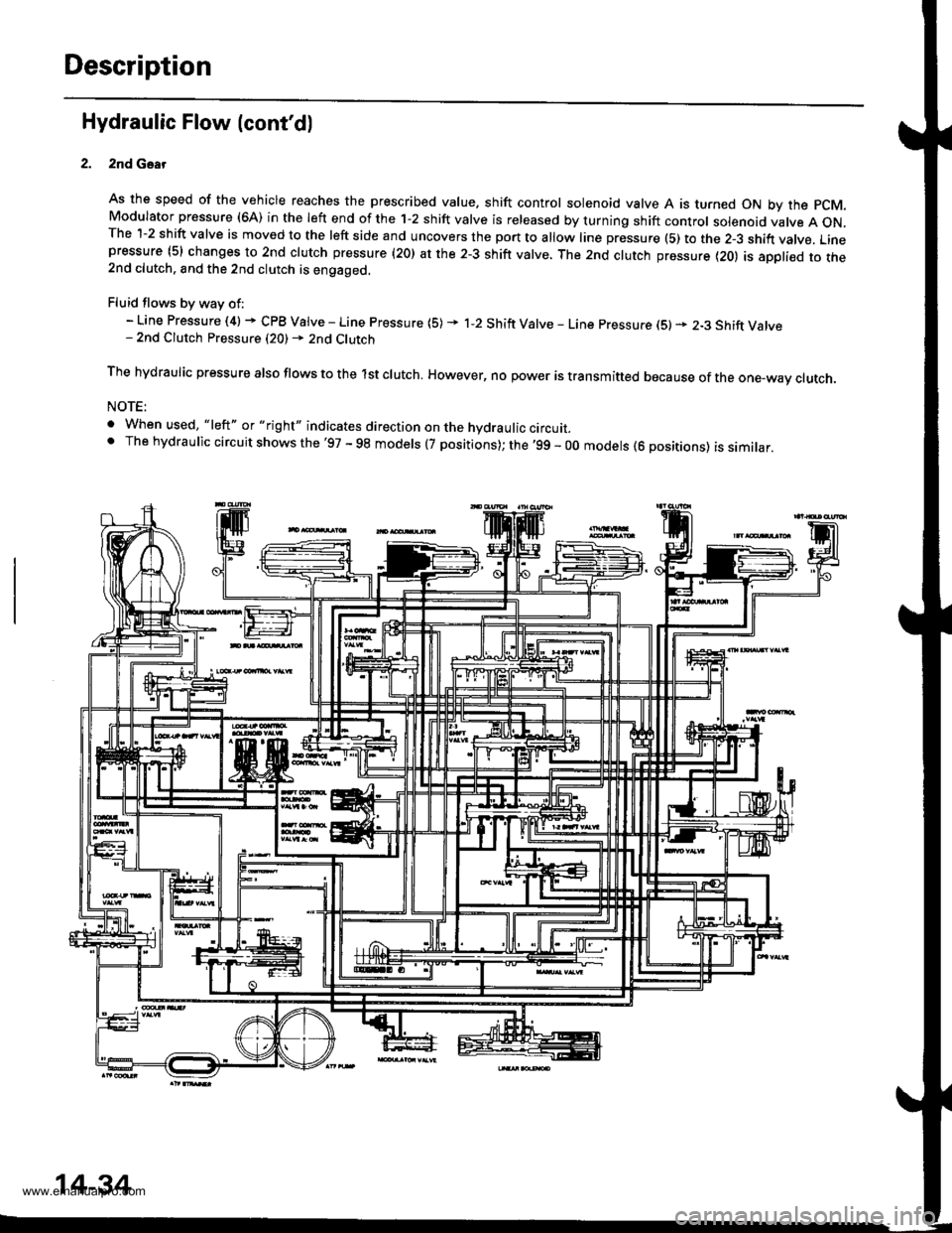
Description
Hydraulic Flow (cont'dl
2nd Gsar
As the speed of the vehicle reaches the prescribed value. shift control solenoid valve A is turned ON by the pCM.Modulator pressure (6A) in the left end of the 1-2 shift valve is released by turning shift control solenoid valve A ON.The 1-2 shift valve is moved to the left side and uncovers the port to allow line pressure (5) to the 2-3 shift vatve. Linepressure (5) changes to 2nd clutch pressure (20) at the 2-3 shift valve, The 2nd clutch pressure {20) is appli€d to the2nd clutch. and the 2nd clutch is engaged.
Fluid flows by way of:- Line Pressure (4) + CPB Valve - Line Pressure (5) * 1-2 Shift Valve - Line pressure (S) * 2-3 Shift Valve- 2nd Clutch Pressure (20) - 2nd Clutch
The hydraulic pressure also flows to the lst clutch. However, no power is transmitted because of the one-wav ctutch.
NOTE:
. When used, "|eft" or "right" indicates direction on the hydraulic circurr_' The hydraulic circuit shows the'97 - 98 models (7 positions); the '99 - 00 models (6 positions) is similar,
14-34
www.emanualpro.com
Page 551 of 1395
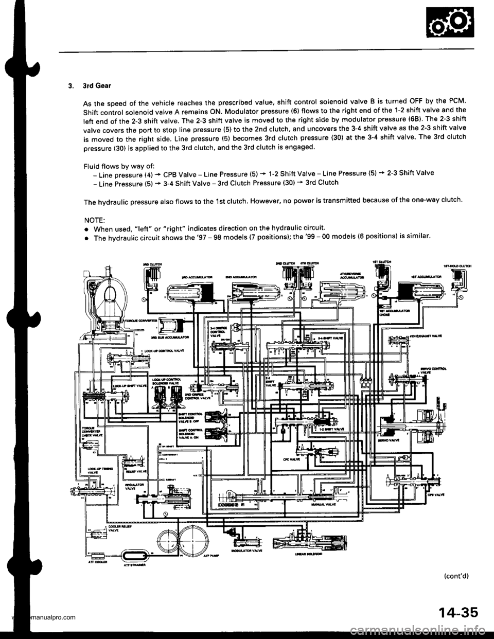
3. 3rd Gear
As the speed of the vehicle reaches the prescribed value. shift control solenoid valve B is turned OFF by the PCM.
Shift control solenoid valve A remains ON. Modulator pressure (6) flows to the right end of the 1-2 shift valve and the
left end of the 2-3 shift valve. The 2-3 shift valve is moved to the right side by modulator pressure (68) The 2-3 shift
valve covers the port to stop line prsssure (5) to the 2nd clutch. and uncovers the 3-4 shift valve as the 2-3 shift valve
is moved to the right side, Line pressure (5) becomes 3rd clutch pressure (30) at the 3-4 shift valve. The 3rd clutch
pressure (30) is applied to the 3rd clutch, and the 3rd clutch is engaged.
Fluid flows by way of:- Line pressure (4) - CPB Valve - Line Pressure (5) * 1-2 Shift Vaiv€ - Line Pressure (5) * 2-3 Shift Valve
- Line Pressure (5) * 3-4 Shift Valve - 3rd Clutch Pressure (30) * 3rd Clutch
The hvdraulic Dressure also flows to the 1st clutch. However, no power is trsnsmitted because of the one-way clutch.
NOTE:
. When used, "|eft" or "right" indicates direction on ths hydraulic circuit.
. The hvdraulic circuit shows the '97 - 98 models (7 positions); the'99 - 00 models (6 positions) is similar.
(cont'd)
14-35
www.emanualpro.com
Page 552 of 1395
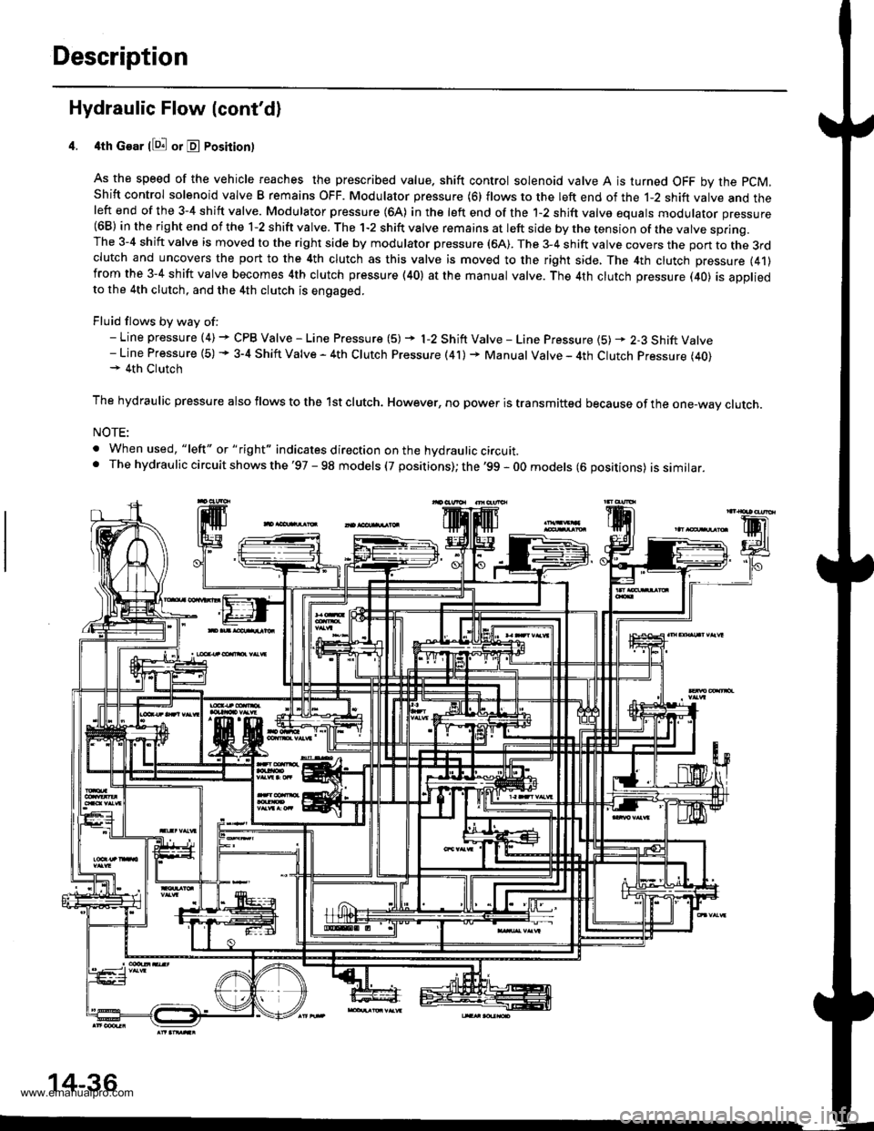
Description
Hydraulic Flow (cont'd)
4th Gear llQ! or E Posirion)
As the speed of the vehicle reaches the prescribed value. shift control solenoid valve A is turned OFF by the pCM,
Shift control solenoid valve B remains OFF. Modulator pressure (6) flows to the left end of the 1-2 shift valve and theleft end of the 3-4 shift valve. Modulator pressure (64) in the left end of the 1-2 shift valve equals modulator pressure(68) in the right end of the 1-2 shift valve. The 1-2 shift valve remains at left side by the tension of the valve spring.The 3-4 shift valve is moved to the right side by modulator pressure (6A). The 3-4 shift valve covers the pon to the 3rdclutch and uncovers the port to the 4th clutch as this valve is moved to the right side, The 4th clutch pressure (41)from the 3-4 shift valve becomes 4th clutch pressure (40) at the manual valve. The 4th clutch pressure (40) is appliedto the 4th clutch, and the 4th clutch is engaged.
Fluid flows by way of:- Line pressure (4) + CPB Valve - Line Pressure (5) + l-2 Shift Valve - Line Pressure {5) * 2-3 Shift Valve- Line Pressure (5) + 3-4 Shift Valve - 4th Clutch Pressure (41) + Manual Valve - 4th Clutch Pressure (40)+ 4th Clutch
The hydraulic pressure also flows to the lst clutch. However, no power is transmitted because of the one-wav clutch.
NOTE:
. When used, "lelt" or " tight" indicates direction on the hydraulic circuit.. The hydrau lic circuit shows the '97 - 98 models (7 positions); the '99 - 0O models (6 oositions) issimilar.
14-36
www.emanualpro.com
Page 553 of 1395
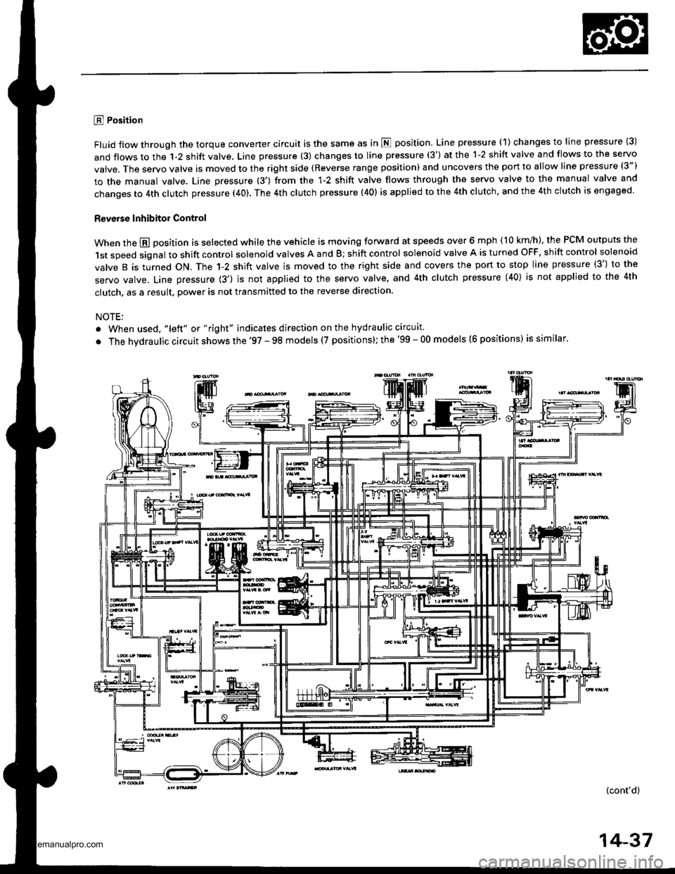
E Position
Fluid flow through the torque converter circuit is the same as in N position. Line pressure (1) changes to line pressure (3)
and flows to the 1-2 shift valve. Line pressure (3) changes to line pressure (3') at the 1-2 shift valve and flows to the servo
vaive. The servo valve is moved to the right side (Reverse range position) and uncovers the port to allow line pressure (3")
to the manual valve. Line pressure (3') from the 1-2 shift valve flows through the servo valve to the manual valve and
changes to 4th clutch pressure (40). The 4th clutch pressure (40) is applied to the 4th clutch, and the 4th clutch is engaged.
R€verse Inhibitor Control
When the @ position is selected while the vehicle is moving forward at speeds over 6 mph (10 km/h), the PCM outputs the
1st speed signal to shift control solenoid valves A and B; shift control solenoid valve A is turned OFF, shift control solenoid
valve B is turned ON. The 1-2 shift valve is moved to the right side and covers the port to stop line pressure (3') to the
servo valve. Line pressure {3') is not applied to the servo valve, and 4th clutch pressure (40} is not applied to the 4th
clutch, as a result, power is not transmitted to the reverse direction.
NOTE:
. When used, "lelt" ot " right" indicates direction on the hydraulic circuit.
. The hvdraulic circuit shows the '97 - 98 models (7 positions); the '99 - 00 models (6 positions) is similar'
(cont'd)
14-37
www.emanualpro.com
Page 554 of 1395
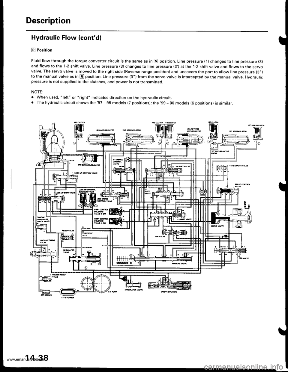
Description
Hydraulic Flow (cont'dl
E Position
Fluid flow through the torque converter circuit is the same as in fl position. Line pressure ( 1) changes to line pressure (3)
and flows to the 1-2 shift valve. Line pressure (3) changes to line pressure {3') at the 1-2 shift valve and flows to the servovalve. The servo valve is moved to the right side (Reverse range position) and uncovers the port to allow line pressure (3")
to the manual valve as in E position. Line pressure (3") from the servo valve is intercepted by the manual valve. Hydraulicpressure is not supplied to the clutches, and power is not transmitted.
NOTE:
. When used, "left" or "right" indicates direction on the hydraulic circuit.. The hydraulic circuit shows the '97 - 98 models (7 positions); the '99 - 00 models (6 positions) issimilar.
14-38
www.emanualpro.com
Page 555 of 1395
Lock-up System
TOROUE CONVERTER
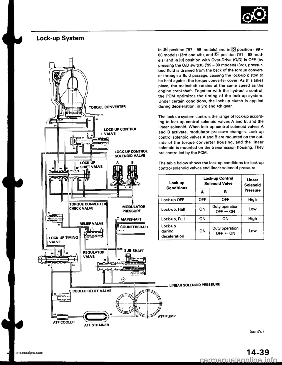
In E position ('97 - 98 models) and in E position ('99 -
OO models) (3rd and 4th), and E position ('97 - 98 mod-
els) and in E position with Over-Drive (O/D) is OFF (by
pressing the O/D switch) ('99 - 00 models) (3rd), pressur-
ized fluid is drained from the back of the torque convert-
er through a fluid passage, causing the lock-up piston to
be held against the torque converter cover, As this takes
Dlace, the mainshaft rotates at the same speed as th8
engine crankshaft. Together with the hydraulic control,
the PCM optimizes the timing of the lock-up system.
Under certain condltions. the lock-up clutch is appli€d
during deceleration, in 3rd and 4th gear.
The lock-up system controls the range of lock-up sccord-
ing to lock-up control solenoid valves A and B, and ths
linear solenoid. When lock-up control solenoid valves A
and B activate. modulator pressure changes. Lock-up
control solenoid valves A and B are mounted on the out-
side of the torque converter housing, and the linear
solenoid is mounted on the transmission housing. They
are controlled bv the PCM.
The table below shows the lock-up conditions for lock-up
control solenoid valves and linear solenoid pressure.
LINEAR SOLENOID PRESSURE
(cont'd)
LOCK.UP CONTROL' VALVE
LOCK.UP CONTROLSOLENOID VALVE
AB
MODULATORPf,ESSURE
MAINSHAFT
COUNTERSHAFT
SUB.SHAFT
Lock-up
Conditions
Lock-up Conirol
Solenoid valveLinaal
Solenoid
PrgssulsAB
Lock-up OFFOFFOFFHigh
Lock-up, HalfONDuty operation
OFF - ONLow
Lock-up, FullONONHigh
Lock-up
during
deceleration
ONDuty operation
OFF - ON
RELIEF VALVE
LOCK'UP TIMINGVALVE
COOLER RELIEF VALVE
ATF COOLERATF STRAINER
ATF PUMP
14-39
www.emanualpro.com
Page 652 of 1395
Shift Control Solenoid Valve A/B Assembly
Test
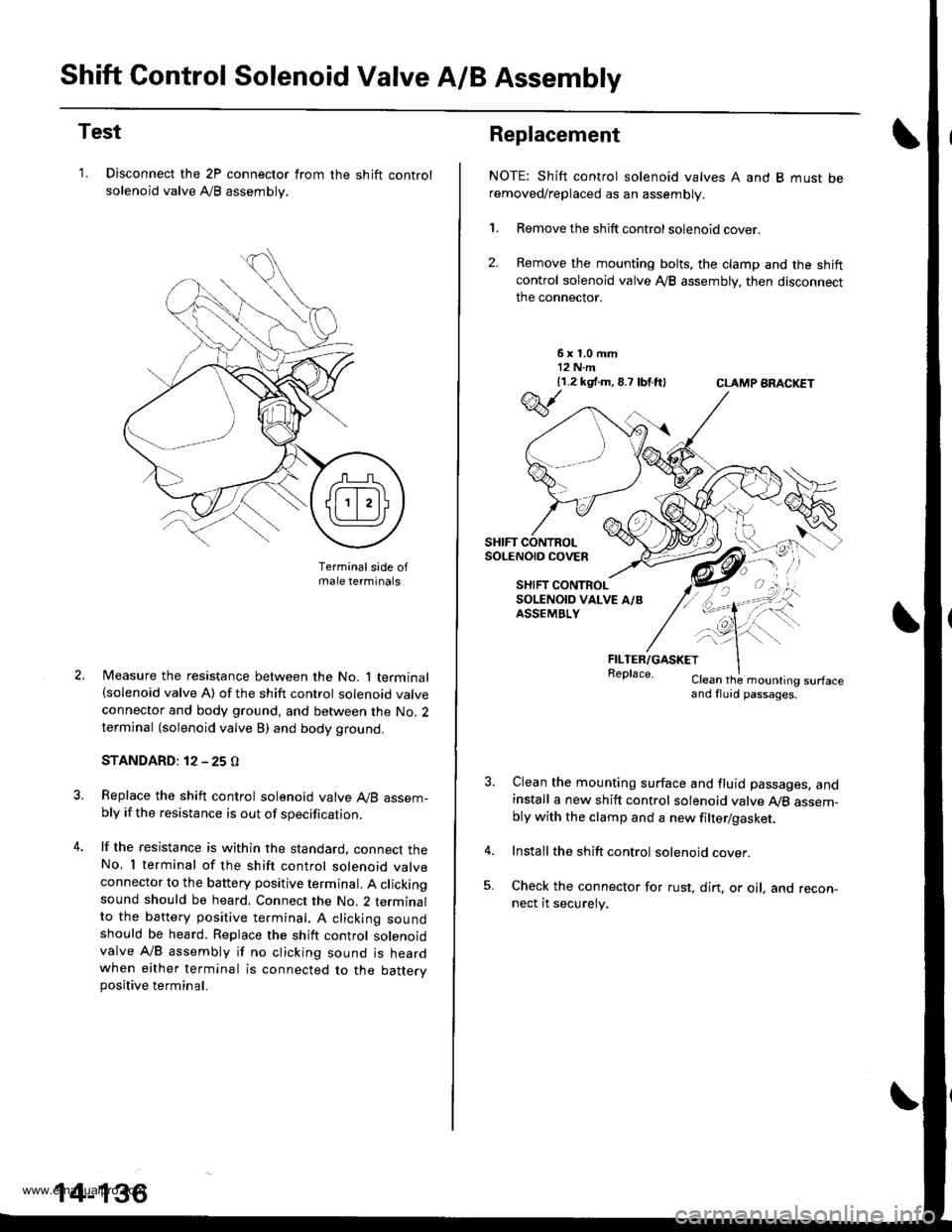
'1. Disconnect the 2P connector from
solenoid valve Ay'B assembly.
the shift control
Terminalsade ofmale terminals
Measure the resistance between the No. 1 terminal(solenoid valve A) of the shift control solenoid valve
connector and body ground, and between the No. 2terminal (solenoid valve B) and body ground.
STANDARD: 12 - 25 O
Replace the shift control solenoid valve A,/B assem-bly if the resistance is out of specification.
lf the resistance is within the standard. connect theNo, I terminal of the shift control solenoid valveconnector to the battery positive terminal. A clickingsound should be heard. Connect the No. 2 terminalto the battery positive te.minal. A clicking soundshould be heard. Replace the shift control solenoidvalve A/B assembly if no clicking sound is heardwhen either terminal is connected to the battervpositive terminal.
14-136
Replacement
NOTE: Shift control solenoid valves A and B must beremoved/replaced as an assembly.
1. Remove the shift control solenoid cover.
2. Remove the mounting bolts, the clamp and the shiftcontrol solenoid valve Ay'B assembly, then disconnect
the connector.
6x1.0mm12 N.m{1.2 k9 .m,8.7 lbtft}CLAMP ARACKET
FILTER/GASKETReplace.Clean the mounling surfaceand fluid passages.
Clean the mounting surface and fluid passages. andinstall a new shift control solenoid valve Ay'B assem-bly with the clamp and a new filter/gasket.
Install the shift control solenoid cover.
Check the connector for rust, dirt. or oil, and recon-nect it securely.
w
SHIFT CONTROLSoLENO|O COVEn
SHIFT CONTROLSOLENOID VALVE A/BASSEMBLY
\--
qK
-!t'">,,
www.emanualpro.com
Page 672 of 1395

Symptom-to-Com ponent Chart
Hydraulic System (cont'd)
NOTES
See flushing procedure, page l4-264 and 265,
BSet idle rpm in gear to specified idle speed. lf still no good, adjust motor mounts as outlined in enginesection of this manual.
clf the large clutch piston O-ring is broken, inspect the piston groove for rough machining.
Dlf the clutch pack is seized or is excessively worn. inspect the other clutches fot wear, and check the orificecontrol valves, CPC valve, and linear solenoid for free movement.
lf the linear solenoid is stuck, inspect the clutches for wear.
lf the 1-2 shift valve is stuck closed. the transmission will not upshift. lf stuck open, the transmission hasno lst gear.
Hlf the 2nd orifice control valve is stuck, inspect the 2nd and 3rd clutch Dacks for wear.
lf the 3-4 orifice control valve is stuck, inspect the 3rd and 4th clutch packs for wear.
Jlf the clutch pressure control valve is stuck closed. the transmission will not shift out of lst gear.
Klmproper alignment of main valve body and torque converter housing may cause ATF pump seizure. Thesymptoms are mostly an rpm-related ticking noise or a high-pitched squeak.
Llf the ATF strainer is clogged with particles of steel or aluminum, inspect the ATF pump and differentialpinion shaft. lf both are OK and no cause for the contamination is found, replace the torque converter.
Mlf the lst clutch feed pipe guide in the end cover is scored by the mainshaft. inspect the ball bearing forexcessive movement in the transmission housing. lf oK, replace the end cover as it is dented. The o-rinounder the guide is probably worn.
N' Replace the mainshaft if the bushing for the 4th feed pipe is loose or damaged, lf the 4th feed pipe is darrFaged or out of round. replace the end cover.' Replace the mainshaft if the bushing for the l st feed pipe is loose or damaged. lf the 1st feed pipe is dam-aged or out of round, replace it.
oA worn or damaged sprag clutch is mostly a result of shifting the transmission in E!. E, or E positionwhile the wheels rotate in reverse. such as rocking the vehicle in snow.
PInspect the frame for collision damage.
lnspect for damage and wear:
l. Reverse selector gear teeth chamfers.
2. Engagement teeth chamfers of countershaft 4th and reverse gear.
3. Shift fork for scuff marks in center.
4. Differential pinion shaft for wear under pinion gears.
5. Bottom of 3rd clutch for swirl marks.
Replace items 1, 2, 3. and 4 if worn or damaged. lf transmission makes a clicking, grinding, or whirring noise,also replace mainshaft 4th gear, reverse idler gear, and countershaft 4th gear in addition to 1,2, 3, or 4.lf differential pinion shaft is worn, overhaul differential assembly, replace ATF strainer, and thoroughly cjeantransmission, flush torque converter. cooler, and lines,lf bottom of 3rd clutch is swirled and transmission makes gear noise. replace the countershaft and final drivenoear,
Be very careful not to damage the torque converter housing when replacing the main ball bearing. you
may also damage the ATF pump when you torque down the main valve body. This will result in ATF pumpseizure if not detected. Use the Drooer tools.
SInstall the main seal flush with the torque converter housing. lf you push it into the torque converterhousing until it bottoms out, it will block the fluid return passage and result in damage.
www.emanualpro.com
Page 685 of 1395

Transmission
Removal
@
2.
'1.
Make sure lifts. iacks, and safety stands aro placed
properly, and hoist brackets are attached to the col-
rest position on the engine lsee section 11.
Apply th€ parking brake and block the r€ar wheels,
so vehicls will noi roll off the stands and fall on you
while working under it.
NOTE: Use fender covers to avoid damaging painted
surfaces.
Disconnect the negative terminal, then disconnect
the positive terminal from the battery.
Remove the intake air duct and the air cleaner hous-
ing assembly,
Remove the starter cables. Remove the harness
clamp from the clamp bracket.
5.
STARTERCABLES
Remove the transmission ground cable terminal
and the radiator hose clamp lrom the transmission
hanger.
Disconnect the lock-up control solenoid valve con-
nector, then remove the harness clamp from the
clamp bracket.HARNESS CLAMP
RADIATOR HOSECLAMP
CONTROLSOLENOID VALVECONNECTOR
CLAMP
6. Disconnect the vehicle speed sensor (VSS), the coun-
tershaft speed sensor, and the A/T gear position
switch connectors.
A/T GEAR POSITIONSWITCH CONNECTOR
VEHICLE SPEEDSENSOR |VSS'
CONNECTORBfiACKET
SPEED SENSORCONNECTOR
7. Remove the transmission housing mounting bolts.
MOUNTING BOLTS
(cont'd)
14-169
www.emanualpro.com
Page 693 of 1395
![HONDA CR-V 1998 RD1-RD3 / 1.G User Guide
r] REVERSE IDLER GEAR SHAFT/HOLDERA N€EDLE BEARING
..] TRANSMISSION HOUSING
al TRANSMISSION HOUSING OIL SEAL Replace.g SET BING.80 mm Selecrive part
O REVERSE GEAR COLLABE couNTERSHAFT REVERSE GEA HONDA CR-V 1998 RD1-RD3 / 1.G User Guide
r] REVERSE IDLER GEAR SHAFT/HOLDERA N€EDLE BEARING
..] TRANSMISSION HOUSING
al TRANSMISSION HOUSING OIL SEAL Replace.g SET BING.80 mm Selecrive part
O REVERSE GEAR COLLABE couNTERSHAFT REVERSE GEA](/img/13/5778/w960_5778-692.png)
r] REVERSE IDLER GEAR SHAFT/HOLDER'A N€EDLE BEARING
..] TRANSMISSION HOUSING
al TRANSMISSION HOUSING OIL SEAL Replace.g SET BING.80 mm Selecrive part
O REVERSE GEAR COLLABE couNTERSHAFT REVERSE GEAB
.9,] NEEDLE BEARINGi9 LOCK WASHER Replace..1!i REVERSE SHIFT FORKO REVERSE SELECToRiJ. REVERSE SELECTOR HUBii' COUNTERSHAFT 4TH GEAR.14 NEEDLE BEARINGiD D|STANCE coLLAR,28 mm Selective part(i3 COUNTERSHAFT 2NO GEABi7-] THRUST NEEDLE BEARING(10 COUNTERSHAFT 3RD GEAR(9 NEEDLE BEARINGE9 COUNTERSHAFI3RD GEAB COLLAR.li THRUST NEEDLE BEARING.?) SPLINEO WASHER,,O 3RD CLUTCH ASSEMBLY
€1 O-RING Beplace.i23 COUNTERSHAFT
4i SHIFT CONTROL SOLENOID COVER
?Z] HARNESS CLAMP BRACKET
?9] SHIFT CONTROL SOLENOID VALVE A/B ASSEMBLY
8 HARNESS CLAMP BRACKET
GI SHIFT CONTROL SOLENOID VALVE FILTER/GASKET
(4 MAINSHAFT 2ND GEARi49 NEEDLE BEARING
@ THRUST NEEDLE BEARING(49 MAINSHAFT
@r SEAL|NG R|NG,35 mm
O SEALING RING,29 mm
@ NEEDLE BEARING
.49 SET RING
€) lST.HOLD CLUTCH ASSEMBLY
O o-RING Replace.6E THRUST WASHER
€9 THRUST NEEDLE BEARING
6' NEEDLE EEARING
€ir SUB-SHAFT 4TH GEAR
6 THRUST NEEDLE BEARING
@ SUB.SHAFT 4TH GEAR COLLAR@ sUB-sHAFf
6I NEEDI-E B€ARING STOP
@ NEEDLE BEARING(6t ATF GUIDE CAP Replace.(64 TRANSMISSION HANGEB
@ BREATHER CAP
i@ MAINSHAFT SPEED SENSOR
6i O-RING Replace.
6D REVERSE IDLER GEAR
@r DOWEL PlN, 14 x 25 mm.6d SNAP RINGS
QlI SUB.SHAFT TRANSMISSION HOUSING BEARING
E) MAINSHAFT TRANSMISSION HOUSING BEABING.2, COUNTERSHAFI TRANSMISSION HOUSINGBEARING
@[E
t,n9t0@)@),lD
04
@
@@:���������������.ro)
ai
Replace-SNAP RINGTHRUST WASHEBTHRUST NEEDLE BEARINGMAINSHAFT 4TH GEARNEEDLE BEARINGSTHRUST NEEDLE BEARINGMAINSHAFT 4TH GEAB COLLAR2NO/4TH CLUTCH ASSEMBLYO-RING Replace.THRUST WASHER,36.5 x 55 mm Selective partTHRUST NEEOLE BEARING
DOWEL PlN, 14 x 25 mmCONNECTOR BRACKETATF MAGNETDOWEL PlN, 14 x 20 mmTRANSMISSION HOUSING GASKET Replace.DIFFERENTIAL ASSEMBLYDOWEL PlN, 10 x 12 mmO-RING Replace.TRANSFER ASSEMBLYTOROUE CONVERTER HOUSING OIL SEAL Replace.TOROUE CONVERTER HOUSING
TOROUE SPECIFICATIONS
Bolt/Nut No.Torque ValueSizeRgmarks
6A
6B
10A
12 N.m (1.2 kgf.m,8.7 lbf.ft)
14 N.m (1.4 kgf.m, 10 lbift)
44 N.m (4.5 kgf.m,33 lbf.ft)
6x 1.0 mm
6x 1.0 mm
10 x 1.25 mm
14-177
www.emanualpro.com