electrical fuse HONDA CR-V 1998 RD1-RD3 / 1.G User Guide
[x] Cancel search | Manufacturer: HONDA, Model Year: 1998, Model line: CR-V, Model: HONDA CR-V 1998 RD1-RD3 / 1.GPages: 1395, PDF Size: 35.62 MB
Page 1100 of 1395

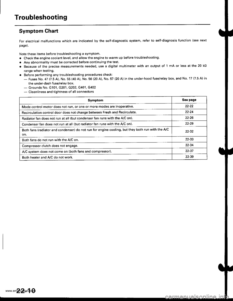
Troubleshooting
Symptom Ghart
For electrical malfunctions which are indicated by the self-diagnostic system, reter to selt-diagnosjs function (see next
page).
Note these items before troubleshooting a symptom.
. Check the engine coolant level, and allow the engine to warm up before troubleshooting.
. Anv abnormality must be corrected before continuing the test.
. Because of the precise measurements needed, use a digital multimeter with an output of 1 mA or less at the 20 kO
range when testing.
. Before performing any troubleshooting procedures check:
- Fuses No. 47 17.5 AJ, No. 55 (40 A), No. 56 (20 A), No. 57 (20 A) in the under-hood fuse/relay box, and No. 17 {7.5 A) in
the under-dash fuse/relay box.._ Grounds No. G101, G201, G202, G401, G4O2
- Cleanliness and tightness of all connectors
SymptomSse pags
Mode control motor does not run, or one or more modes are inoperative.
Recirculation control door does not change between Fresh and Recirculate.22-24
Radiator fan does not run at all (but condenser fan runs with the AVC on).
Condenser fan does not run at all {but radiator fan runs with the Ay'C on).22-29
Both fans (radiator and condenser) do not run for engine cooling. but they both run with the A,/C
on.
Both fans do not run with the Ay'C on22-33
Compressor clutch does not engage.22-34
AJC svstem does not come on (both fans and compressor).22-37
Both heater and A/C do not work,22-39
22-10
www.emanualpro.com
Page 1161 of 1395

Body Electrical
Speciaf Toofs ,...,..,.............-.23-2
Troubleshooting
Tips and Precautions ......,.,..........,.................. 23-3
Five-step Troubleshooting ........,.,.,...,,.,......... 23-5
Wire Color Codes ...,....,.. 23-5
Relay and Control Unit Locations
Engine Compartment ..,.,......,......................... 23-6
Dashboard ,.,.,..............-.- 23-7
Door ....................... .........23-10
Index to Cilcuits and Sysiems
Accessory Socket .. ,....,.,..,.,. 23-95*Airbags ................ .,....,. Sestion 24
Air Conditioning ,.,.,.... Section 22
Alternator ................... Section 4
Anti-lock Brake System {ABSI ................... Section 19'A/T Gear Position Indicator ....................... Section 1,1
Automatic Transmission System ...........,.. Section 14
Battery ................... ..............23-50
Blower Controls .,...,.,, Section 22
Charging System ....... Seqtion il
Clock -'98 Model ................ 23-98
Connector ldentification and Wire HarnessRouting .................. ......... 23.11
Cruise Control ............ Ssction 4
Dash Lights Brightness Contlo||er ..................... 23-90
Fan Conlrols ...,......,.... Section 10
Fuel Pump ,..,.,...,....,.... Section 11
Fuses...................... .,,.,.,.,.,,.,23-40*Gauges
Circuit Diagram ......-....-..23-58
Fuel Gauge .....,.,..... Section 11
Speedometer ..,..........,... 23-56
Ground Distribution ,....,.,...23-46
Hatch Glsss ODenor .........................,.,.,.,.,..,.,.,.,,. 23-121
Heater Controls .-........ Soction 21*Horns.,...,..,.,.,....... ................23"104*fgnition Switch ,,.,.,..,.,.,,.,.,.,23-51
lgnition Key Light System -'97 Mod6l .............. 23.88
-+
BODY
www.emanualpro.com
Page 1166 of 1395

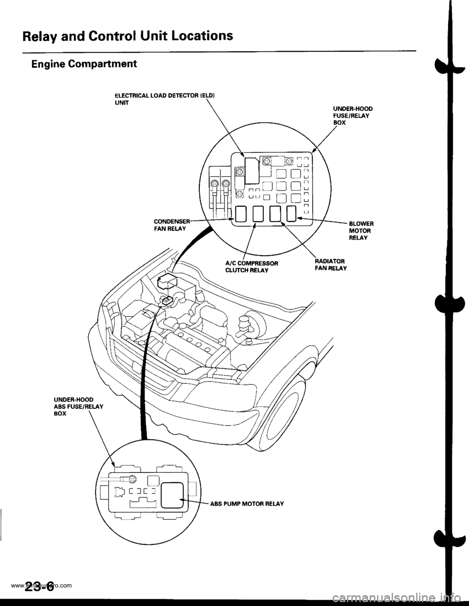
Relay and Control Unit Locations
Engine Compartment
ELECTRICAL LOAD DETECTOR IELDIUNITUNDER.HOODFUSE/RELAYBOX
BLOWERMOTORRELAY
A/C COMPRESSORCLUTCH RELAY
RADIATORFAN EELAY
UNDER.HOODABS FUSE/RELAYBOX
t:
tr
tr
tr
;
-
''r@
Dl-- r rr r
23-6
www.emanualpro.com
Page 1214 of 1395

lgnition Switch
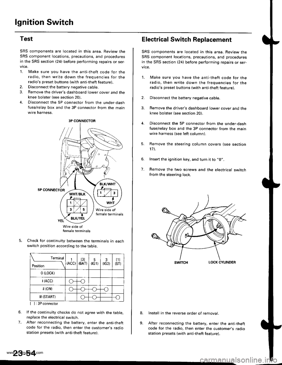
Test
SRS components are located in this area. Review the
SRS component locations, precautions, and procedures
in the SRS section {24} before performing repairs or ser
vtce.
L lMake sure you have the anti-theft code for the
radio, then write down the frequencies for theradio's preset buttons (wilh anti-theft feature).
2. Disconnect the battery negative cable.
3. Remove the driver's dashboard lower cover and the
knee bolster {see section 20).
4. Disconnect the 5P connector from the under-dash
fuse/relay box and the 3P connector from the main
wtre narness,
5P CONNECTOR
Wire side oftemale terminals
Check tor continuity between the terminals in eachswitch position according to the table.
rernrnal
ros[ron \
I(ACC)I3l{BAT}5flG1)30G2iI1llsrl
0 (LocK)
r(Acclo--o
fl (oN)G_o
III (START)o--.o
7.
{ I | 3P connector
lf the continuity checks do not agree with the table,replace the electrical switch.
After reconnecting the battery, enter the anti-theftcode for the radio, then enter the customer's radio
station presets (with anti-theft feature).
23-54
3P CONNECTOR
Electrical Switch Replacement
SRS components are located in this area. Review the
SRS component locations, precautions, and procedures
in the SRS section {24) before performing repairs or ser-vice.
1. Make sure you have the anti-thett code for the
radio, then write down the frequencies for the
radio's preset buttons (with anti-theft feature).
2. Disconnect the battery negative cable.
3. Remove the driver's dashboard lower cover and the
knee bolster (see section 20).
4. Disconnect the 5P connector from the under,dash
tuse/relay box and the 3P connector f.om the main
wire harness {see left column).
7.
Remove the steering column covers (see section'17 t.
Insert the ignition key, and turn it to "0".
Remove the two screws and the electrical switchfrom the steering lock,
swrTcHLOCK CYLINDER
lnstall in the reverse order of removal.
After reconnecting the battery, enter the anti-theftcode for the radio, then enter the customer's radiostation presets (with antj-theft feature).
9.
www.emanualpro.com