fuel cap HONDA CR-V 1998 RD1-RD3 / 1.G User Guide
[x] Cancel search | Manufacturer: HONDA, Model Year: 1998, Model line: CR-V, Model: HONDA CR-V 1998 RD1-RD3 / 1.GPages: 1395, PDF Size: 35.62 MB
Page 380 of 1395
Fuel Supply System
System Description
The fuel supply system consists of a fuel tank, in-tank
high-pressure fuel pump. PGM-Fl main relay, fuel filter,
fuel pressure regulator, fuel injectors, and fuel delivery
and return lines. This system delivers pressure-regulat-
ed fuel to the fuel injectors and cuts the fuel delivery
when the engine is not running.
Fuel Pressure
Relieving
Before disconnecting fuel pipes or hoses, release pres-
sure from the system by loosening the 12 mm banjo
bolt on the too of the fuel filter.
Do not smoke while working on the fuel system.
Ke€p open flames or sparks away from your work
area,
Be sure to relieve fuel pressure while the ignition
switch is off.
Write down the frequencies for the radio's preset
buttons.
Disconnect the battery negative cable from the bat-
tery negative terminal.
Remove the fuel fill cap.
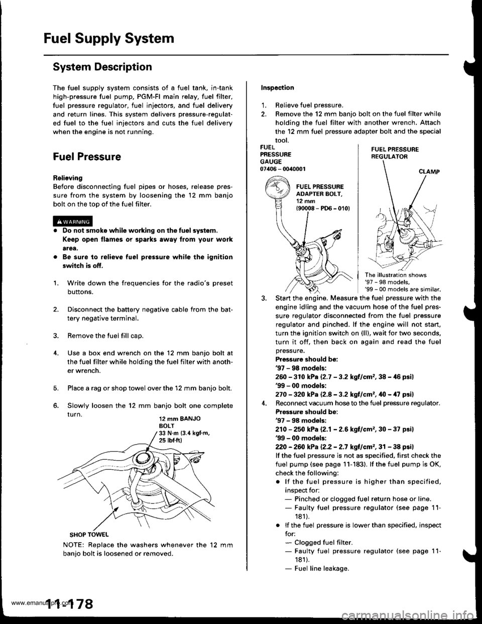
Use a box end wrench on the 12 mm banjo bolt at
the fuel filter while holding the fuel filter with anoth-
er wrench.
Place a rag or shop towel over the '12 mm banjo bolt.
Slowly loosen the 12 mm banjo bolt one complete
rurn 12 mm BANJoBOLT
1.
SHOP TOWEL
NOTE: Replace the washers whenever the 12 mm
banio bolt is loosened or removed.
11-178
Inspection
1, Relieve fuel pressure.
2. Remove the 12 mm banjo bolt on the fuel filter while
holding the fuel filter with another wrench. Attach
the 12 mm fuel pressure adapter bolt and the special
tool.
FUEL PRESSUREREGULATON
FUELPRESSUREGAUGE07406 - 0040001
The illustration shows'97 - 98 models,'99 - 00 models are similar.
Start the engine. Measure the fuel pressure with the
engine idling and the vacuum hose of the fuel pres-
sure regulator disconnected from the fuel pressure
regulator and pinched. lf the engine will not start,
turn the ignition switch on (ll), wait for two seconds,
turn it off, then back on again and read the fuel
pressure.
Pressure should be:'97 - 98 mod€ls:
260 -31O kPa 12.7 - 3.2 kgf/cm,, 38 - 46 psil'99 - 0O models:
270 - 32O kPa Q.A - 3.2 kgf/cm'�, ifo - /U psil
Reconnect vacuum hose to the fuel pressure regulator.
Prgs3ure should be:'97 - 98 models:
210 - 25O kPa 12.1- 2.6 kgf/cm'�, 30 - 37 psi)'99 - 00 models:
22O -26iJ kPa 12.2 - 2.7 kgt/cm'�, 31 - 38 psi)
lf the fuel pressure is not as specified, first check the
fuel pump (see page 11- 183). lf the fuel pump is OK,
check the following:
. lf the fuel pressure is higher than specified,
inspect for:- Pinched or clogged fuel return hose or line.- Faulty fuel pressure regulator (see page 11-
181).
. lf the fuel pressure is lower than specified. inspect
for:- Clogged fuel filter.- Faulty fuel pressure regulator (see page 11-
1811.- Fuel line leakage.
www.emanualpro.com
Page 385 of 1395
Fuel Pump
Testing
lf you suspect a problem with the fuel pump, check that
the fuel pump actually runs; when it is oN (ll), you will
hear some noise if you hold your ear to the fuel fill port
with the fuel fill cap removed. The fuel pump should run
for two seconds when ignition switch is first turned ON (ll).
lf the fuel pump does not make noise, check it as follows:
1. Fold the left rear seat cushion forward, and remove
the base frame cover (see section 20).
2, Remove the access panel from the floor.
3. Make sure the ignition switch is OFF, then discon-
nect the fuel pumP 5P connector.
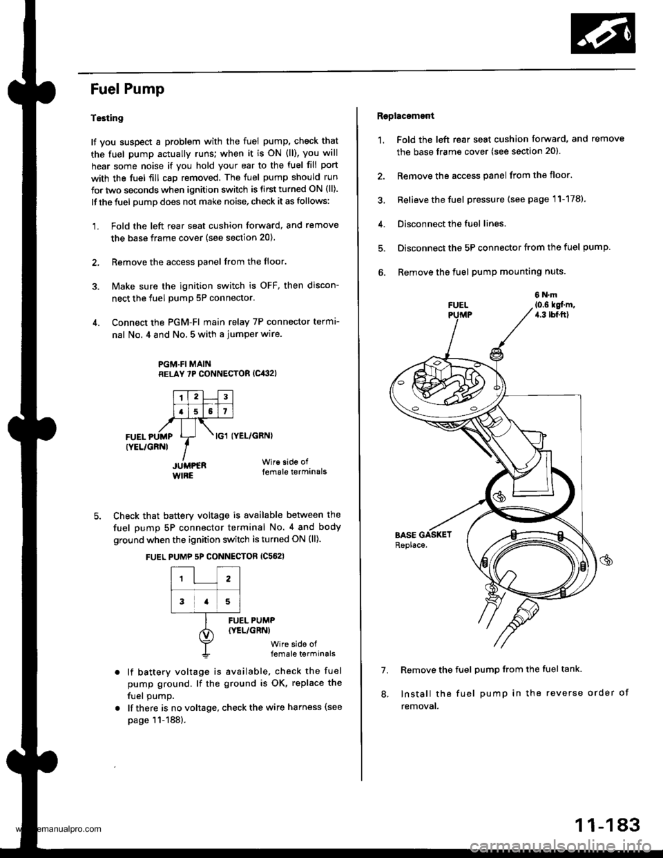
4. Connect the PGM-FI main relay 7P connector termr-
nal No. 4 and No, 5 with a jumper wire.
PGM.FI MAINRELAY 7P CONNECTOR (Cit:}2l
I'TtlJilt f -r'-r ll.l5l517l,frTt-,at\FUEL pUMp Lr- . tcl tyEL/cRNl
rYEL/cRNl IIJUMPER Wir€ side of
WIRE female terminals
5. Check that battery voltage is available between the
fuel pump 5P connector terminal No. 4 and body
ground when the ignition switch is turned ON (ll).
FUEL PUMP 5P CONNECTOR {C562}
12
3a5
lf battery voltage is available, check the fuel
pump ground. lf the ground is OK, replace the
fuel oumo.
lf there is no voltage, check the wire harness (see
page 11-188).
FUEL PUMP(YEL/GRNI
wire side offemale terminals
Raplac6mont
1. Fold the left rear seat cushion forward, and remove
the base frame cover (see section 20).
2. Remove the access panel from the floor.
3, Relieve the fuel pressure (see page 11-178).
4. Disconnect the fuel lines.
5. Disconnect the 5P connector from the fuel pump.
6. Remove the fuel pump mounting nuts.
7. Remove the fuel pump from the fuel tank.
Install the fuel pump in the reverse order of
removal.
8.
11-183
www.emanualpro.com
Page 405 of 1395
EVAP PURGE CONTROL SOLENOID VALVE DUTY CONTROLLED AFTER
STARTING ENGINE
ENGINE COOLANT TEMPERATURE ABOVE 154"F (68'C)
Evaporative Emission (EVAP) Controls
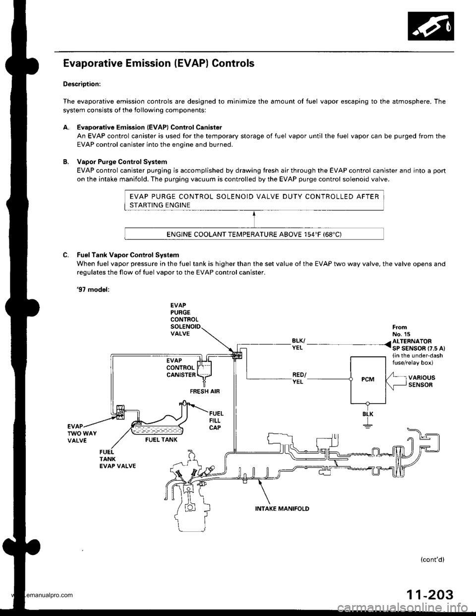
Description:
The evaporative emission controls are designed to minimize the amount of fuel vapor escaping to the atmosphere. The
system consists of the following components:
A. Evaporative Emission (EVAPI Control Canister
An EVAP control canister is used for the temporary storage of fuel vapor until the luel vapor can be purged from the
EVAP control canister into the enqine and burned.
B. Vapor Purge ConirolSystem
EVAP control canister purging is accomplished by drawing fresh air through the EVAP control canister and into a pon
on the intake manifold. The purging vacuum is controlled by the EVAP purge control solenoid valve.
C. Fuel Tank Vapor Control System
When fuel vapor pressure in the fuel tank is higher than the set value of the EVAP two way valve, the valve opens and
regulates the flow ot fuel vapor to the EVAP control canister.
'97 model:
EVAPPURGECONTROL
VALVEFromNo. 15BLK/ /ALTERNATORYEL I sP SENSOR r7.s At(in the under-dashfuse/relay box)
VARIOUSSENSORFEESH AIF
BLK
I
FUEI- TANK
(cont'd)
11-203
INTAKE MANIFOLD
www.emanualpro.com
Page 410 of 1395
Emission Control System
Evaporative Emission (EVAP) Controls (cont'd)
99 - 00 models:
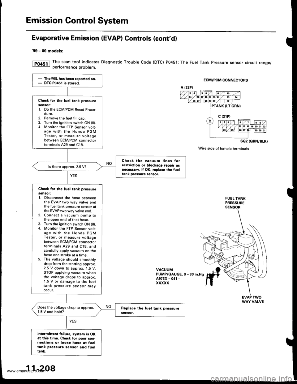
The scan tool indicates Diagnostic Trouble Code {DTC) P0451: The Fuel Tank Pressure sensor circuit range/oerformance Droblem.
ECM/PCM CONNECTORS
SG2 {GRN/BLK)
Wire side of {emaleterminals
FUEL TANKPRESSURESENSOR
VACUUMPUMP/GAUGE.0 -30 in.H9A973X - 041 -
XXXXX
- The MIL har been rooort€d on.- DTC P0451 b storod.
Check lor th6 tu6l tank pr€ssurelen30r:1. Do the ECM/PCM Reset Proce,oure.2. Remove the fuelfill cap.3. Turn the ignition switch ON (ll).4. Monitor the FTP Sensor voltage with the Honda PGMTester, or measure voltagebetween ECM/PCM connectorterminals A29 and C18.
Chock tho vacuum lin6s torrGlriction o. blockago repair asnecessary. lf OK, roplace the fueltank Drer3ur€ sentor.
ls there approx. 2.5 V?
Check for the fuel tank piessureSensot:L Disconnect the hose betweenthe EVAP two way valve andthe fuel tank pressure sensor atthe EVAP two way valve end.2. Connect a vacuum pump tothe open end ofthat hose.3. Turn the ignition switch ON (lll.4. Monitor the FTP S€nsor volt-age with the Honda PGMTester, or measure voltagebetween ECNI/PCNI connectorterminals A29 and C18, andcarefully appiy vacuum on thehose one stroke at a time.5. The voltage should smoothlydrop from the staning approx.2.5 V down to approx. 1.5 V.STOP applying vacuum whenthe voltage drops to approx.1.5 V or damage to the tueltank pressure sensor may
Does the voltage drop to approx.1.5 V and hold?
Intermittent tailuro. sv3tem is OKat this tim€. Chack to. poor con-n€ction6 or 10036 hose at fu6ltank pres3ure ionsor and fueltrnk.
a t32Pl
PTANK ILT GRNI
WAY VALVE
11-208
www.emanualpro.com
Page 411 of 1395
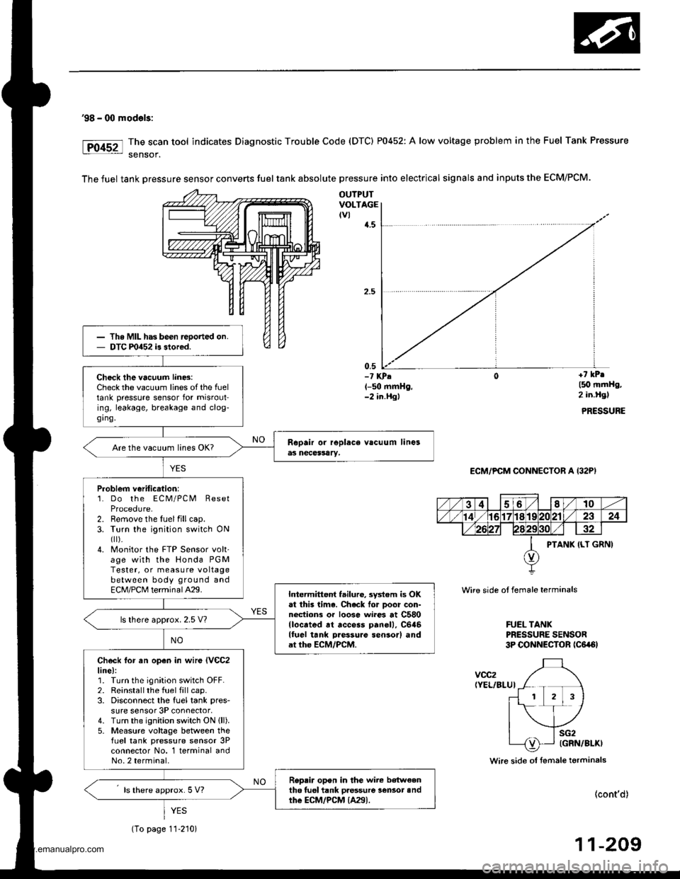
'98 - 00 mod€ls:
The scan tool indicates Diagnostic Trouble Code (DTC) P0452: A low voltage problem in the Fuel Tank Pressure
sensof.
The fuel tank Dressure sensor converts fuel tank absolute pressure into electrical signals and inputs the ECM/PCM.
OUTPUTVOLTAGEtvl{.5
0,5-? KPA(-50 mmHg,-2 in.Hgl
+7 kPr
l5O mmHg,2 in.Hgl
PRESSURE
ECM/PCM CONNECTOR A (32P)
Wire side ot female terminals
FUEL TANKPRESSURE SENSOR3P CONNECTOR tc6a6l
voc2(YEL/BLUI
Wire side ol fsmale terminals
(cont'd)
11-209
Th. MIL has been reoorted on.DTC m452 is stored.
Check the vacuum lin6:Check the vacuum lines of the fueltank pressure sensor for misrouting, leakage, breakage and clog-ging.
Are the vacuum lines OK?
Problem veriticstion:1. Do the ECM/PCM ResetProcedure-2. Remove the luelfillcap.3. Turn the ignition switch ONfl r).4. Monitor the FTP Sensor volt'age with the Honda PGMTester, or measure voltagebetween body ground andECM/PCM terminalA29.Intermittent failuro, system is OKat this lima. Chack lor Door con-nections or loose wi.es at C580llocrted rt access panell, C646lluel tank Daessure sensor) andat the ECM/PCM.
ls lhere approx. 2.5 V?
Check lor an open in wir€ lVeC2line):1. Turn the ignition switch OFF.2. Reinstallthe fuel fill cap.3. Disconnect the fuel tank pres-
sure sensor 3P connector,4. Turn the ignition switch ON (ll).
5- Measure voltage between thefLrel tank pressure sensor 3Pconnector No. 1 terminal andNo.2 terminal.
Replir opon in the wire b€tw€enth6 tuel tank pressure lensot andthe ECM/PCM {A29).ls there approx. 5 V?
YES
(To page 11-210)
www.emanualpro.com
Page 413 of 1395
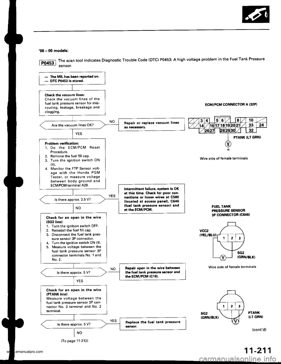
'98 - 00 modals:
The scan tool indicates Diagnostic Trouble Code (DTC) P0453: A high voltage problem in the Fuel Tank Pressure
sensor.
ECM/PCM CONNECTOR A {32PI
Wire sido ot fema16 t€rminals
FUEL TANXPf,ESSUBE SENSOR3p CONNECTOR {C6,a6l
vcc2IYEL/BLUI
sG2IGRN/BLKI
sG2(GRN/BLK}
Wire side ot female terminals
PTANKILT GRNI
(cont'd)
11-211
PTANK ILT GRN)
123
Thc MIL has b6on ropottcd on.DTC mia53 is dorcd.
Ch6ck tho vacuum linos:Check the vacuum lines of the
fuel tank pressure sensor lor mis-
routing, leakage, breakage and
cloggrng.
Are the vacuum lines OK?
Problorn verif ication:1. Do the ECM/PCM ResetProcedute.2. Remove the fuel fill cap.
3. Turn the ignition switch ON
{[).4. Monitor the FTP Sensor volt-age with the Honda PGM
Tester, or measure voltagebetween body ground and
ECM,PCM terminal429.Intarmittent tailuro, sv3iom b OKat this timo. Chock for poor con-nection3 or loo$ wire3 at C580(locstod .t .cc$r p.nell, C6a6(fucl tank pros3ure son3orl and.t the ECM/FCM.
ls there approx. 2.5 V?
Check lor an open in tho wiro
lSG2lin6l:1. Turn the ignition switch OFF.
2. R6installthe Iuel fill cap.3. Disconnect the Iu6l tank pres_
sure sensor 3P connector,4. Turn the ignition switch ON (ll).
5. M€asure voltago between thetuel tank pressure sensor 3P
connector terminals No. '! andNo.2.
Replir op€n in th. wi.c b€{weentha fuel tank Dio'sute sansot andtho EC|,/PCM {Cl8}.ls there approx. 5 V?
Ch€ck for an opon in tho wiro(PTANK linel:Measure voltage between thefuel tank pressure sensor 3P con-nector No. 3 terminal and No. 2terminal.
ls there approx. 5 V?
\To page 11-212)
www.emanualpro.com
Page 415 of 1395
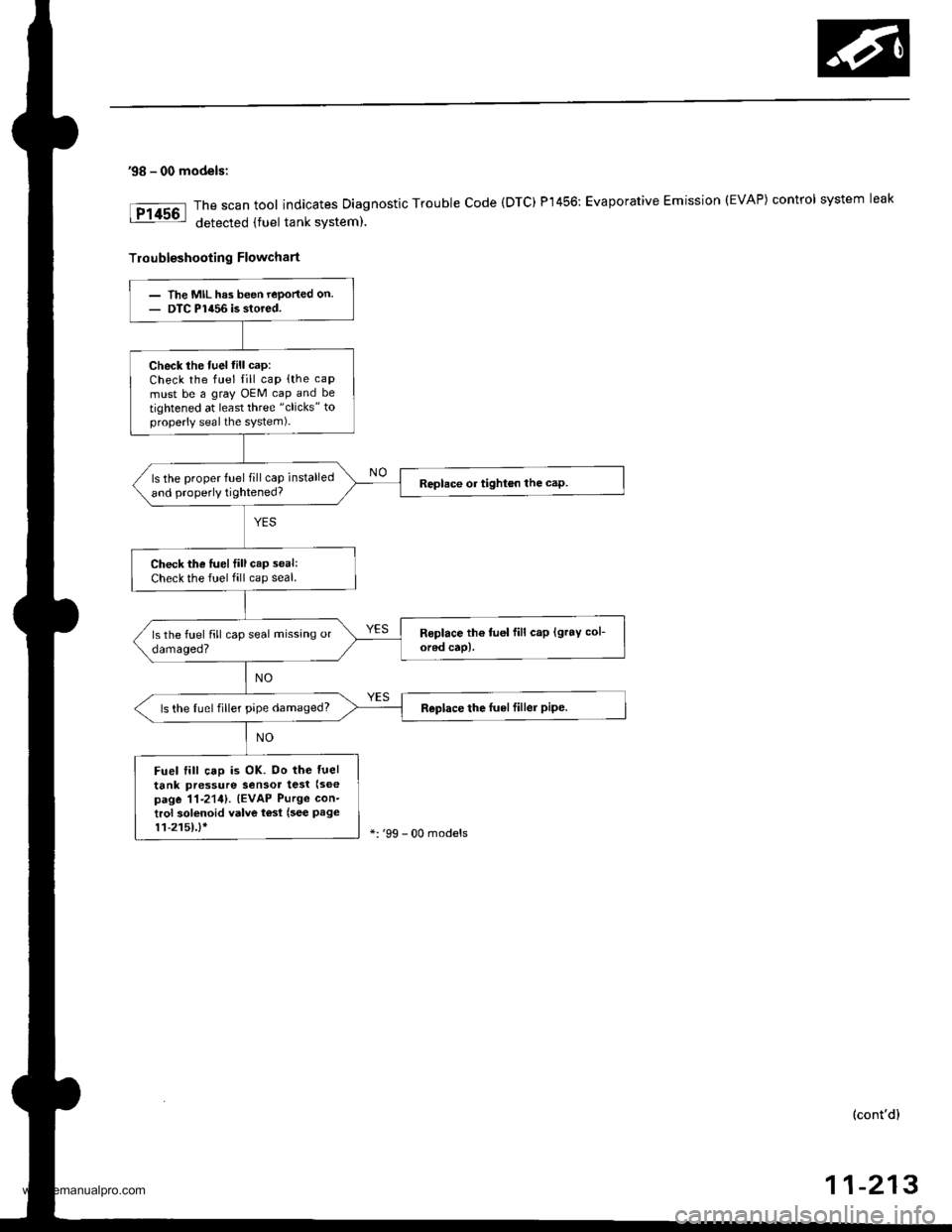
'98 - 00 models:
The scan tool indicates Diagnostic Trouble code (DTC) P1456: Evaporative Emission (EVAP) control system leak
detected {fuel tank system).
Troubleshooting Flowchart
- The MIL has been reported on.- DTC P1456 is stored.
Check the fuel fill cap:Check the fuel fill cap (the caP
must be a gray OEM cap and be
tightened at least three "clicks" toproperly seal the system)-
ls the proper fuel fill cap installed
and properly tightened?Replace or tighton the cap.
Check the lueltill cap seal:
Check the fuel fill cap seal.
Replace the luelfiller pipe.ls the tuel filler pipe damaged?
Fuel till caD is OK. Do the luel
tank pressure Sensor test (see
page 11-2111. (EVAP Purge con-
trol solenoid valve t€sl (see Page11-2151.1r':'99 - 00 models
(cont'd)
11-213
www.emanualpro.com
Page 420 of 1395
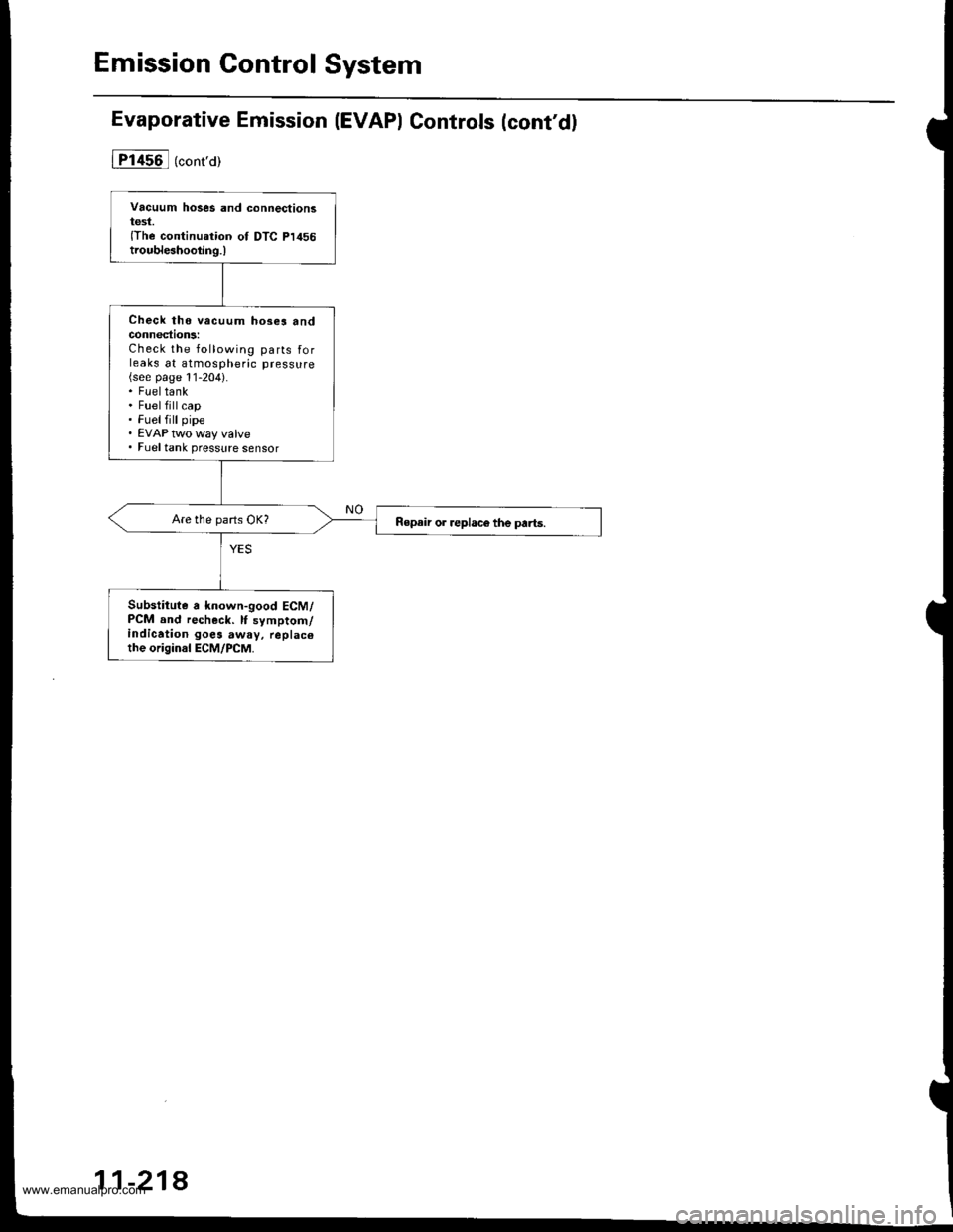
Emission Control System
Evaporative Emission IEVAPI Controls (cont'd)
lTi,t56l ("onto)
Vacuum hoses and connectionstelit.(The continuarion of DTC P1456troubleshooiing.l
Check the vacuum ho3es andconnect|ons:Check the following parts forleaks at atmospheric p ressu re{see page 11-204).. Fueltank. Fuel fill cap. Fuelfill pipe. EVAP two way valve. Fueltank pressure sensor
Repair or replaco the parts.
Substitute a known-good ECM/PCM and recheck. lf symptom/indication goes away, replac€the original ECM/PCM.
11-218
www.emanualpro.com
Page 425 of 1395
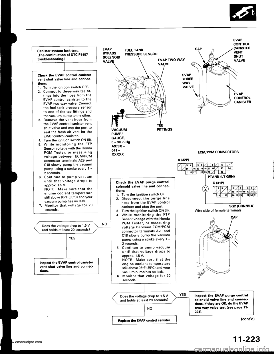
Canbter system leak test
{The continuation of DTC P1457
trouble3hootin9.)
Chock the EVAP control canistervent shut valve line and connoc'
tonS:1. Turn the ignition switch OFF
2. Connect to three'way tee fit_
tings into the hose from the
EVAP control canister to the
EVAP two way valve. Connect
the fuel tank pressure sensor
to one of the tee fittings and
the vacuum PumP to the other'
3. Remove the vent hose from
the EVAP control canister vent
shut valve and cap the Pon to
seal the fresh air vent Ior the
EVAP control canister.4. Turn the ignition switch ON (ll).
5. While monitoring the FTP
Sensor voltage with the Honda
PGM Tester, or measurangvoltage between ECM/PCM
connector terminals A29 and
C18 slowly PumP the vacuumpump using a stroke every 1 -
2 seconds.6. Continue to PumP vacuum
until that voltage droPs to
approx. 1.5 V.NOTE: Make sure that the
engine coolant temPeraturestillabove 95'F (35'Cland Yourvacuum PumP has no leak
7. Monitor that voltage for 20
seconds.
Check the EVAP Pu.ge control
solenoid valve line and connec-
tions:1. Turn the ignition switch OFF.
2. Disconnect the Purge lane
hose from the EVAP control
canister and Plug the Port3. Turn the ignition switch ON (lli.
4. While monitoring the FTP
Sensor voltage with the Honda
PGM Tester, or measuringvoltage between ECM/PCM
connector terminals A29 and
Cl8 slowly PumP the vacuumpump using a stroke every 1 -
2 seconds.5. Continue to pump vacuum
until that voltage droPs to
approx. 1-5 V.NOTE: Make sure that the
engine coolant temPeraturestill above 95'F (35"C) and Yourvacuum pump has no leak-
6. Monitor that voltage tor 20
seconds.
Doesthe voltage drop to 1.5 V
and holds at least 20 seconds?
lGp€ct the EVAP control cani3tel
vent 3hut valvo line and connec_
tion5.
Inlpect tho EVAP Putge control
solenoid valvo line and connec'
tion3. It th6y lro OK, do the EVAP
two way valve te3t (seo page 11-
2211.
Does the voltage drop to 1.5 V
and holds at least 20 seconds?
Reolace the EVAP conirol canister.
EVAPBYPASSSOLENOIDVALVE
FUEL TANK
EVAPCONTROL
VENTSHUTVALVE
EVAPCONTROLCANISTER
SENSOR
EVAP TWO WAYVALVE
EVAPTHREE
VALVE
ttrrL
ta
VACUUMPUMP/GAUGE,0 - 30 in.HgA973X -
041 -
XXXXX
FITTINGS
ECM/PCM CONNECTORS
A {32P)
PTANK ILT GRN)
c (31Pt
SG2 {GRN/BLK)
Wire side of female terminals
{cont'd)
11-223
www.emanualpro.com
Page 426 of 1395
Emission Control System
Evaporative Emission (EVAP) Controls (cont,dl
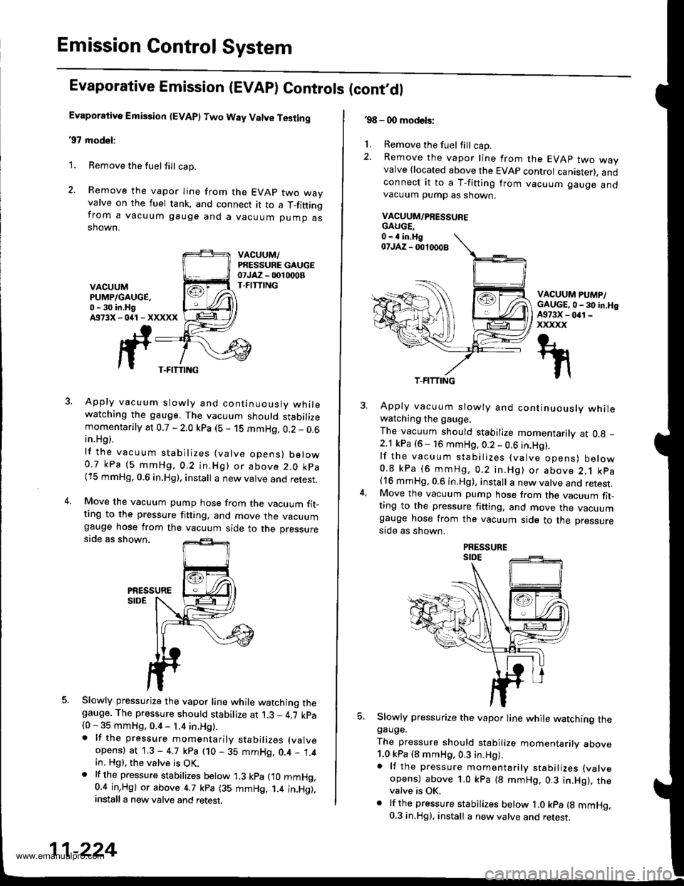
Evaporative Emission (EVAP) Two Way Valve Testing
'97 model:
1. Remove the fuelfill cap.
2. Remove the vapor Iine from the EVAP two wayvalve on the fuel tank, and connect it to a T_fittingfrom a vacuum gauge and a vacuum pump asshown.
VACUUM,/PRESSURE GAUGEotJAz - 001 rDoBT-FITTINGVACUUMPUMP/GAUGE,0 - 30 in.HgA973X-041-XXXXX
3. Apply vacuum slowly and continuouslv whilewatching the gauge. The vacuum should stabilizemomentarily at 0.7 - 2.0 kpa (5 - 1S mmHg, 0.2 _ 0.6in.Hg).
lf the vacuum stabilizes (valve opens) below0.7 kPa (5 mmHg,0.2 in,Hg) or above 2.0 kpa(15 mmHg, 0.6 in.Hg), install a new valve and retest.
4.Move the vacuum pump hose from the vacuum fit_ting to the pressure fitting, and move the vacuumgauge hose from the vacuum side to the pressureside as shown.
PiESSURESIDE
5. Slowly pressurize the vapor line while watching thegauge. The pressure should stabilize at 1.3 - 4.7 kpa(0 - 35 mmHg, 0.4 - 1.4 in.Hg).. lf the pressure momentarily stabilizes (valve
opens) at 1.3 - 4.7 kpa (10 - 35 mmHg, 0.4 _ 1.4in. Hg), the valve is OK.. lf th6 pressure stabilizes below 1.3 kpa fio mmHg,0.4 inrHg) or above 4.7 kpa (35 mmHg, 1.4 in.Hg),install a new valve and retest.
T-FITTING
11-224
.98 - 0O models:
1. Remove the fuel fill cap.2. Remove the vapor line from the EVAP two wayvalve {located above the EVAP control canister). andconnect it to a T-fitting from vacuum gauge andvacuum pump as shown.
VACUUM/PRESSUFE
VACUUM PUMP/GAUGE,0 - 30 in.HgA973X - 041 -
xxxxx
5.
Apply vacuum slowly and continuously whilewatching the gauge.
The vacuum should stabilize momentarily at O.g _
2.1 kPa (6 - 16 mmHg, 0.2 - 0.6 in.Hg).lf the vacuum stabilizes (valve opens) below0.8 kPa (6 mmHg, 0.2 in.Hg) or above 2.1 kpa(16 mmHg, 0.6 in.Hg), install a new valve and retest.Move the vacuum pump hose from the vacuum fit-ting to the pressure fitting. and move the vacuumgauge hose from the vacuum side to the pressure
side as shown.
Slowly pressurize the vapor line while watching thegauge.
The pressure should stabilize momentarilv above1.0 kPa (8 mmHg, 0.3 in.Hg).a lf the pressure momentarily stabilizes (valve
opens) above 1.0 kPa (8 mmHg. 0.3 in.Hg), thevalve is OK.. lf the pressure stabilizes below ,|.0 kpa {g mmHg.0.3 in.Hg), install a new valve and retest.
T-FITTING
www.emanualpro.com