24-23 HONDA CR-V 1998 RD1-RD3 / 1.G Owner's Manual
[x] Cancel search | Manufacturer: HONDA, Model Year: 1998, Model line: CR-V, Model: HONDA CR-V 1998 RD1-RD3 / 1.GPages: 1395, PDF Size: 35.62 MB
Page 1375 of 1395
Troubleshooting
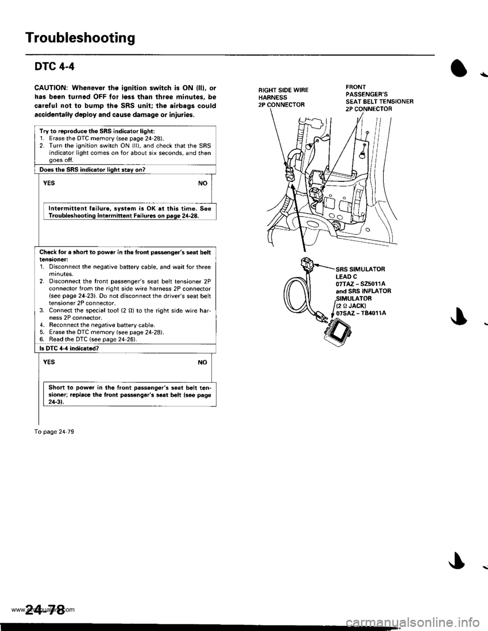
DTC 4-4
CAUTION: Whenever the ignition switch is ON (ll), or
has been turned OFF tor less than thlee minutes. be
careful nol to bump the SRS unit; the airbags could
accidontally deploy and cause damage or iniuries.
RIGHT SIDE WIREHARNESS2P
FRONTPASSENGER'S
SRS SIMULATORLEAD C07TAZ - SZ5011Aand SRS INFLATOR
,StMULATOR/(2 o JACK)
t _07SAZ - TBiro1 1A
Try to reproduce the SRS indicator light:1. Erase the DTC memory {see page 24-28).2. Turn the ignition switch ON (ll), and check that the SRSindicator light comes on for about six seconds, and thengoes off.
Doos the SRS indicator light 3t.y on?
vEsNO
Intermittent f!ilure, system is OK at this time. SeeT.oubleshooting Intermittent F.ilures on page 24-28.
Check tor a 3horl lo power in the frolt pass€nge.'s s€at belttensaoneri'1. Disconnect the negative battery cable, and wait for threemrnutes.2. Disconnect the front passenger's seat belt tensioner 2Pconnector from the right side wire harness 2P connector{see page 24-23}. Do not disconnect the driver's seat belttensioner 2P connector.3. Connect the special tool (2 O) to the right side wire har-ness 2P connector.4. Reconnect the negaiive baftery cable.5. Erase the DTC memory (see page 24-28).6. Read the DTC lsee page24-261.
ls DTC 4-,1 indicated?
YESNO
Short to power in the front passong6r'3 seat belt ten-sioner; replace the front passongar'3 s€at beh {see page21-31.
To page 24'79
24-78.
www.emanualpro.com
Page 1376 of 1395
)
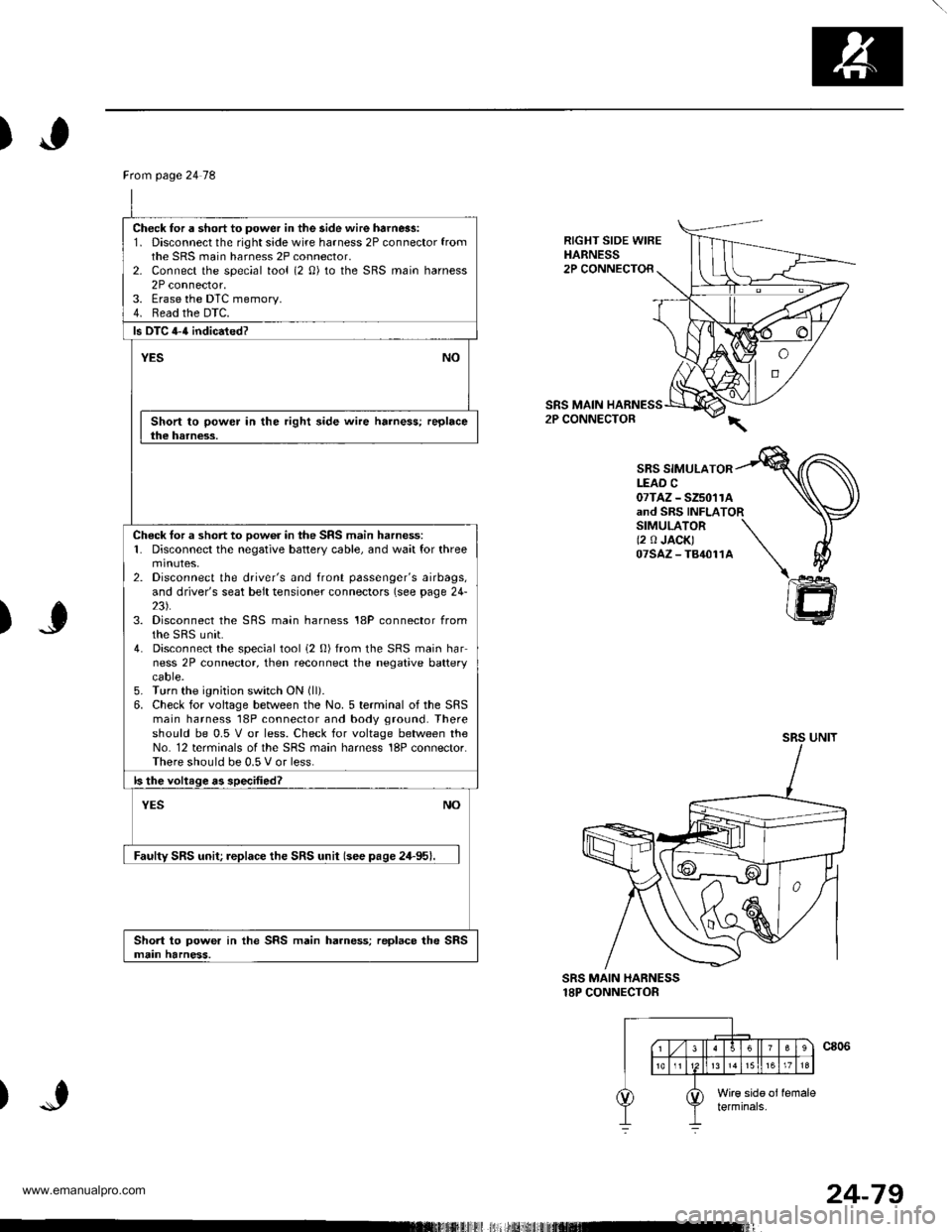
RIGHT SIDE WIREHARNESS2P CONNECTOR
SRS MAIN2P CONNECTOR
SBS SIMULATORLEAD C07TAZ - SZ5011Aand SRS INFLATORSIMULATOR \(2 0 JACK) \07sAz-T84011A \\
)J
)
@
SRS MAIN HARNESS18P CONNECTOR
Ftom page 24 78
Check for a short to power in the side wire harn6s:1. Disconnect the right side wire harness 2P connector fromthe SRS main harness 2P connector,2- Connect the special tool (2 0) to the SRS main harness2P connector.3. Erase the DTC memory.4. Read the DTC.
ls DTC 4-{ indicated?
YESNO
Short to power in the right side wire harness; replacethe harness.
Check tor a short to oow6r in the SRS main harness:1. Disconnect the negative battery cable, and wait for threemtnutes,2. Disconnect the driver's and front passenger's airbags,and driver's seat belt tensioner connectors (see page 24-23).3. Disconnect the SRS main harness 18P connector fromthe sRS unit.4. Disconnect the special tool i2 0) from the SRS main harness 2P connector, then reconnect the negative batterycaore.5. Turn the ignition switch ON (ll).
6. Check for voltage between the No. 5 terminal of the SRSmain harness 18P connector and body ground. Thereshould be 0.5 V or less. Check for voltage between theNo. 12 terminals of the SRS main harness 18P connector.There should be 0.5 V or less.
ls the voltage as specified?
NOYES
Faulty SRS unit; replace the SRS unit (see pase 24-95).
Short to power in the SRS main harness; replace the SRSmain harness.
24-79
www.emanualpro.com
Page 1377 of 1395
Troubleshooting
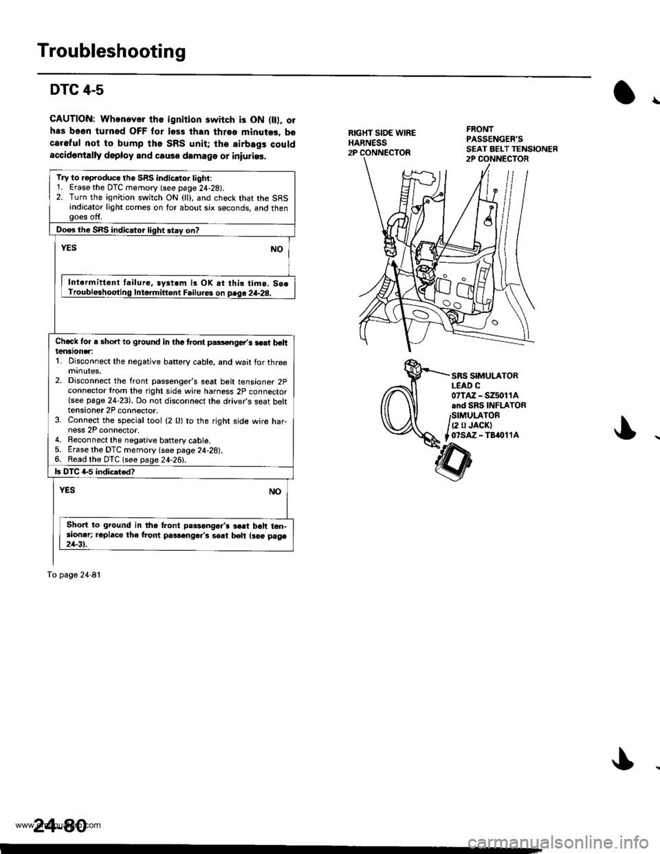
DTC 4-5
GAUTION: Whonever the ignition switch is ON fll). olhas be6n turned OFF for less than thrso minuter. becareful not to bump the SRS unit; the airbags couldaccidontally deploy and causo damage or iniurias.
\
RIGXT SIOE WIREHARNESS2P
FRONTPASSENG€R'S
SRS SIMULATORLEAD C07lAz - s2501 1Aand SRS INFLATORSIMULATOR
t2 0 JACKTo?saz - Taaol 1A
Try to roproduco th. SRS indicrtor tighi:1. Erase the DTC memory (see page 24-28).2. Turn the ignition switch ON (ll), and check that the SRSindicator light comes on for about six seconds, and thengoes off.
Doe3 the SRS indicator light stay on?
YESNO
Int€rmittent t.ilurG, syst.m is OK at thi! timo. So€Troubleshooting Inte.mift€nt Failure3 on psqa 2+28.
Chcck Ior a shon to ground in the trodt pars€nge/s lert behtensionea:1. Disconnect the negative battery cable, and wait for threemrnutes.2. Disconnect the front passenger's seat belt tensioner 2pconnector trom the right side wire harness 2p connector(see page 24-23). Do not disconnect the driver's seat bektensioner 2P connector.3. Connect the special tool (2 0) to the right side wire har-ness 2P connector,4. Reconnect the negative battery cable.5. Erase the DTC memory lsee page 24-28).6. Read the DTC (seo page 24-26!-.
k DIC G5 indicated?
NOYES
Short to ground in the Lont passengc.'3 3€rt boh ton-sioner; replace tho from p.rlenger's sort beh ls€a page21-3t.
To page 24-81
24-80
www.emanualpro.com
Page 1378 of 1395
From page 24'80
Check lor a short to ground in the sido wir€ harness:1. Disconnect the rightsidewire harness 2P connector fromthe SRS main harness 2P connector.2. Connect the special tool {2 O) to the SRS main harness2P connector.3. Erase the DTC memorv.4. Read the DTC.
b DTC 4-5 indicrtad?
YESNO
Short to ground in the right side wire harness; replac.the harne3!.
Check tor a short io ground in the SRS main ha.nessi1. Disconnect the negative battery cable, and wait for threeminotes,2. Disconnect the driver's and front passenger's airbags,and driver's seat belt tonsioner connectors (see page 24-231.3. Disconnect the SRS main harness 18P connector from
4. Disconnect the special tool (2 0) from the SRS main har-ness 2P connector.5. Check resistance between the No. 5 terminal oI the SRSmain harness 18P connector and body ground, andbetween the No. 12 terminal of the SRS main harness18P connector and body ground. There should be 1 M0or more,
b th€ re3i3tance as specified?
NOYES
Faulty SRS unit replace the SRS unit {see pace 2a-951.
Short to ground in the SRS main harness; replace the SRSmain harnoss.
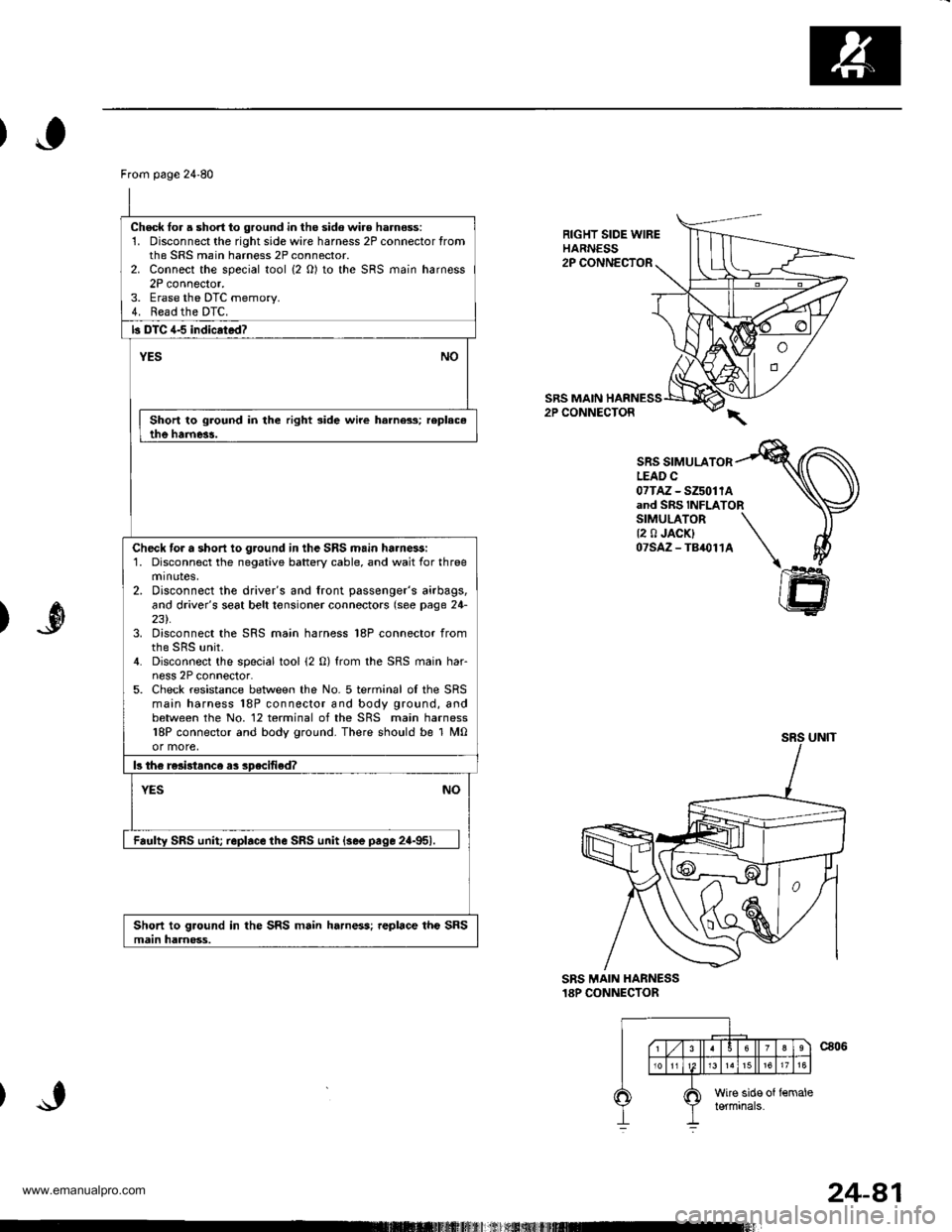
RIGHT SIDE WIREHARNESS2P CONNECTOR
SRS MAIN HARNESS2P CONNECTOR
SRS SIMULATORLEAD C07TAz - SZ5011Aand SRS INFLATORSIMULATOR \{2 0 JACK} \07SAZ-TB,O114 \I
ffi
)
SRS MAIN HANNESS18P CONNECTOR
24-81
www.emanualpro.com
Page 1379 of 1395
Troubleshooting
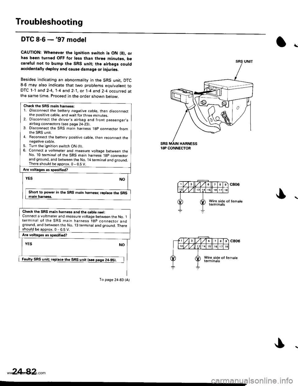
DTC 8-6 -'97 model
CAUTION: Whonever th€ ignition switch is ON fll). olhas b€en turned OFF for les3 than thro€ minutes, becaretul not to bump the SRS unit; tho airbags couldaccidentally deploy and cause damage or iniurios.
Besides indicating an abnormality in the SRS unit, DTC8-6 may also indicate that two problems equivalent toDTC 1-1 and 2-4, 'l-4 and 2-1, or 1-4 and 2-4 occurred atthe same time. Proceed in the order shown below.
18P CONNECTOR
\
Chock the SBS main harnGs:1. Disconnect the battery negative cable, then disconnectthe positive cable, and wait for three minutes.2. Disconnect the driver's airbag and front passenger,safrDag connectors {see page 24-23).3. Disconnect the SRS main harness t8p connector fromthe sRs unit.4. Reconnect the battery posative cable, then reconnect thenegative cable.5. Turn the ignition switch ON 0t).6. Connect a voltmeter and measure voltage between theNo. 10 terminal ot the SRS main harness l8p connectorand ground, and between the No. 14 terminal and qround.There should be aDorox.0-0.5 V.
Are voltages as specitied?
NOYES
Shon to power in tho SRS main harness; reglace the SRSmain harn€63.
Chock the SRS mein harnels and the cable re€l:Connect a voltmeter and measure voltage between the No. 1terminal of the SRS main harness l8p coonector andground, and between the No. 13 terminal and ground. Thereshould be approx.0 0.5 V.
Are voltages as specifiod?
YESNO
Faulty SRS unit; replace the SRS unit {sae pago 24-951.
To page 24-83 (A)
24-82
www.emanualpro.com
Page 1392 of 1395
SRS Unit
).0Replacement
CAUTION:
. Before disconnecting any part of the SRS wire har-
nesg, disconnect the airbag connoctors (and soat beh
tensioner connectorsl.
. During installation or replacament, do not bump(impact wrench, hammer etc.) the area near the SRS
unit.
Do not damage the SFS unit terminalg or connsc-
lors.
Do not disassemble the SRS unit it has no saryice-
able parts,
Store the SRS unit in a clean, dry area.
Do not use any SRS unit which has been subiected
to water damage or shows signs ot being dropped orimproperly handlgd, such as dents, cracks or defor-
mation.
Disconnect the battery negative cable, then discon-
nect the positive cable from the battery, andwaitat
least three minutes.
Disconnect the airbag connectors (and seat belt ten-
sioner connectors). (When disconnected, the airbag
and seat belt tensioner connectors are automatical-
ly shorted.)
Driver's Side:
. Remove the access panel from the steering
wheel, then disconnect the 2P connector
between the driver's airbag and cable reel (see
page 24-231.
Front Passenger's Side:. Disconnect the 2P connector between the frontpassenger's airbag and SRS main harness (see
page 24-231.
Soat Beh Tensionor ('98 - 00 modelsr:. Remove the left and right center pillar lower trimpanels (see section 20).
. Disconnect the seat belt tensioner 2P connectors
from the left side wire harness (driver's side) and
the right wire harness (front passenger's side)(see page 24'231.
2.
a
a
'1.
)
)o
24-95
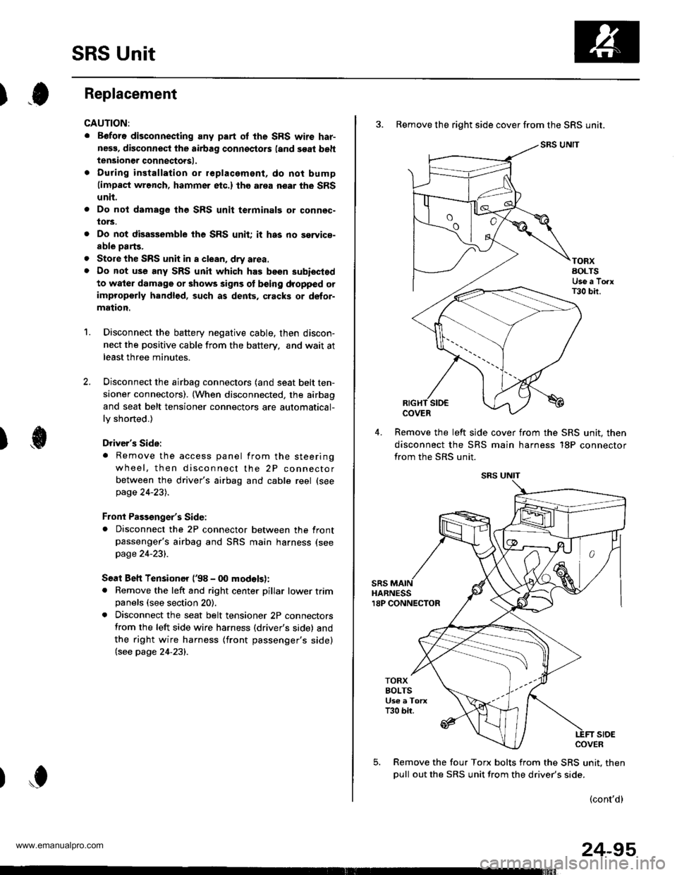
3. Remove the right side cover from the SRS unit.
SRS UNIT
TORXAOLTSUse a TorxT30 bir.
COVER
Remove the left slde cover from the SRS unit. then
disconnect the SRS main harness 18P connector
from the SRS unit.
sRsHARNESS18P CONNECTOR
TORXBOLTSUs€ a TorxT30 bir.
stoECOVER
Remove the four Torx bolts from the SRS unit. then
oull out the SRS unit from the driver's side.
(cont'd)
www.emanualpro.com
Page 1394 of 1395
Airbag/Seat Belt Tensioner
)Disposal
)
Before scrapping any airbags {and seat belt tansioners)
(including those in a whole vehicle to be scrappedl. the
airbags (and seat belt tensioners) must be deployed. lf
the vehicle is still within the warrantv oeriod the Honda
District Service Manager must give approval and/or spe-
cial instructions, before you deploy the airbags (and seat
belt tensioners). Only after the airbags {and seat belt ten-
sioners) have been deployed (as the result of vehicle col-
lision, for example), can they be scrapped.
lf the airbags (and seat belt tensioners) appear intact
(not deployed), treat them with extreme caution.
Follow this procedure:
Doploying tho Airbags (and Soat B6li Ten3ione6):
ln-vehicle
lf an SRS vehicle is to be entirely scrapped, its airbags(and seat belt tensioners) should be deployed while still
in the vehicle. The airbags (and seat belt tensioners)
should not be considered as salvageable parts and
should never be installed in another vehicle.
@ confirm that each airbag {and seat belt
tonsiongr) i3 ggcurely mountod; othgrwise, severe per-
sonal iniury could result from d6ploym6nt,
1. Disconnect the battery negative cable, then discon-
nect the oositive cable.
Confirm that the special tool is functioning properly
by following the check procedure on the tool label
or on page 24-98.
Remove the access panel, then disconnect the 2P
connector between the driver's airbag and the cable
reel (see page 24-23).
Remove the glove box, then disconnect the 2P con-
nector between the front passenger's airbag and
SRS main harness (see page 24-23).
Remove the center pillar lower trim panel, then dis-
connect the 2P connector between the seat belt ten-
sioner and side wire harness ('98 - 00 models) (see
page 24-231.
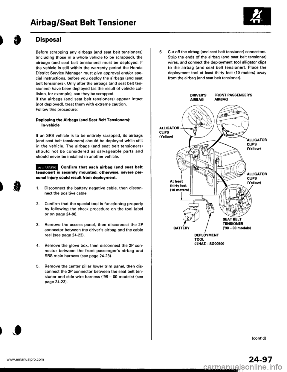
6. Cut off the airbag (and seat belt tensioner) connectors.
Strip the ends of the airbag (and seat belt tensioner)
wires. and connect the deployment tool alligator clips
to the airbag (and seat belt tensioner). Place the
deployment tool at least thirty feet (10 meters) away
from the airbao (and seat belt tensioner),
DRIVER'S FRONTPASSENGER'SAIBBAG AIRBAG
AI.IIGATORcuPslY6llowl
At lcastthirty feot
110 motersl
(cont'd)
24-97
www.emanualpro.com