Bearings HONDA CR-V 1998 RD1-RD3 / 1.G Owner's Manual
[x] Cancel search | Manufacturer: HONDA, Model Year: 1998, Model line: CR-V, Model: HONDA CR-V 1998 RD1-RD3 / 1.GPages: 1395, PDF Size: 35.62 MB
Page 743 of 1395
Transmission Housing Bearings
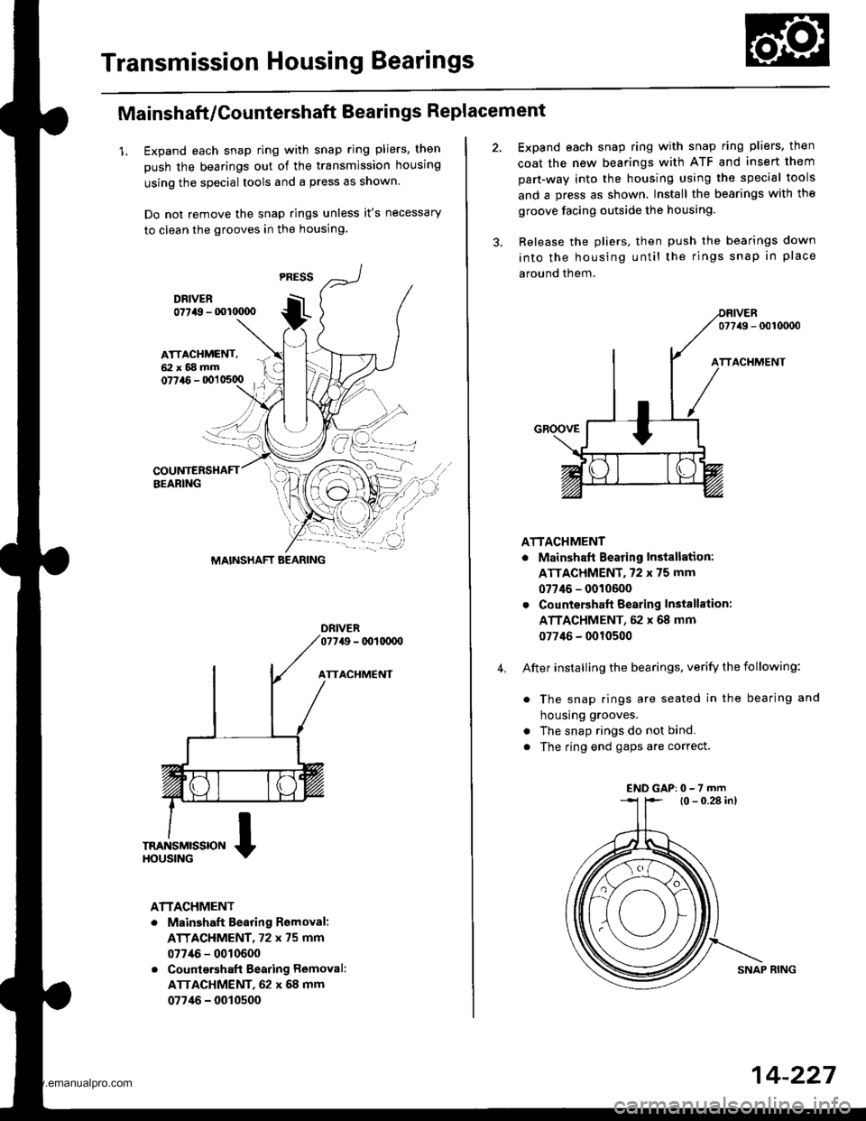
Mainshaft/Countershaft Bearings Replacement
1. Expand each snap ring with snap ring pliers, then
push the bearings out of the transmission housing
using the special tools and a press as shown.
Do not remove the snap rings unless it's necessary
to clean the grooves in the housing.
DFIVER077a9 - 001(xx)o
ATTACHMENT
ATTACHMENT
. Mainshaft Bearing Romoval:
ATTACHMENT, 72 x 75 mm
077/16 - 0010600
. Countqrshaft Bearing Removal:
ATTACHMENT, 62 x 68 mm
07746 - 0010500
MAINSHAFT BEARING
4.
Expand each snap ring with snap ring pliers, then
coat the new bearings with ATF and insert them
part-way into the housing using the special tools
and a press as shown. Install the bearings with the
groove facing outside the housing.
Release the pliers, then push the bearings down
into the housing until the rings snap in place
around them.
077/49 - 0010000
ATTACHMENT
. Mainshaft Bearing Installation:
ATTACHMENT,72 x 75 mm
07746 - 0010600
. Countershaft Bearing Instsllation:
ATTACHMENT, 52 x 68 mm
077'16 - 0010500
After installing the bearings, verify the following:
. The snap rings are seated in the bearing and
housrng grooves.
. The snap rings do not bind.
. The ring end gaps are correct,
l0 - 0.28 in)
SNAP RING
ENDGAP:0-7rnm
14-227
www.emanualpro.com
Page 744 of 1395
Transmission Housing Bearings
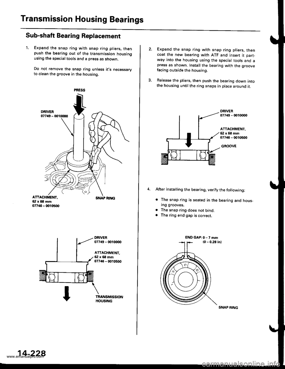
Sub-shaft Bearing Replacement
1. Expand the snap ring with snap ring pliers, thenpush the bearing out of the transmission housingusing the special tools and a press as shown.
Do not remove the snap ring unless it,s necessaryto clean the groove in the housing.
ATTACHMEI{T,5:l x 68 mm07r{5 - @10500
SNAP RI]TG
DRIVER07749 - tDl(xx)o
ATTACHMENT,6:l x 68 mm077a6 - (X,r0500
14-228
SNAP RING
Expand the snap ring with snap ring pliers, thencoat the new bearing with ATF and insert it part-way into the housing using the special tools and apress as shown. lnstall the bearing with the groovefacing outside the housing.
Release the pliers, then push the bearing down intothe housing untilthe ring snaps in place around it.
DRIVER07743 - 0010mo
ATTACHMENT,{i:l x 68 mm07746 - 0010500
GROOVE
After installing the bearing, verify the following:
. The snap rjng is seated in the bearing and hous_ing grooves.
. The snap ring does not bind.. The ring end gap is correct,
ENDGAP:0-7mm
www.emanualpro.com
Page 745 of 1395
Torque Gonverter Housing Bearings
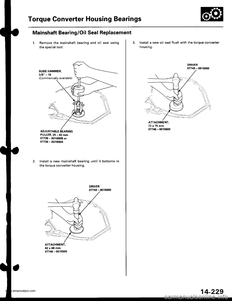
Mainshaft Bearing/Oil Seal Replacement
1. Remove the mainshaft bearing and oil seal using
the soecial tool.
SLIDE HAMMER,3/8" - 16(Commercially available)
ADJUSTABLE EEARINGPULLER,25 - 40 mm07736 - A010008 or07736 - A01000A
ATTACHMENT,62x68mm07746 - 0010500
Install a new mainshaft bearing until it bottoms in
the torque converter housing.
3. Install a new oil seal flush with the torque converter
housing.
ATTACHMENT,
07?46 - 0010m0
07749 - 0010000
14-229
www.emanualpro.com
Page 746 of 1395
Torque Gonverter Housing
BearingsGontrol Lever Assembly
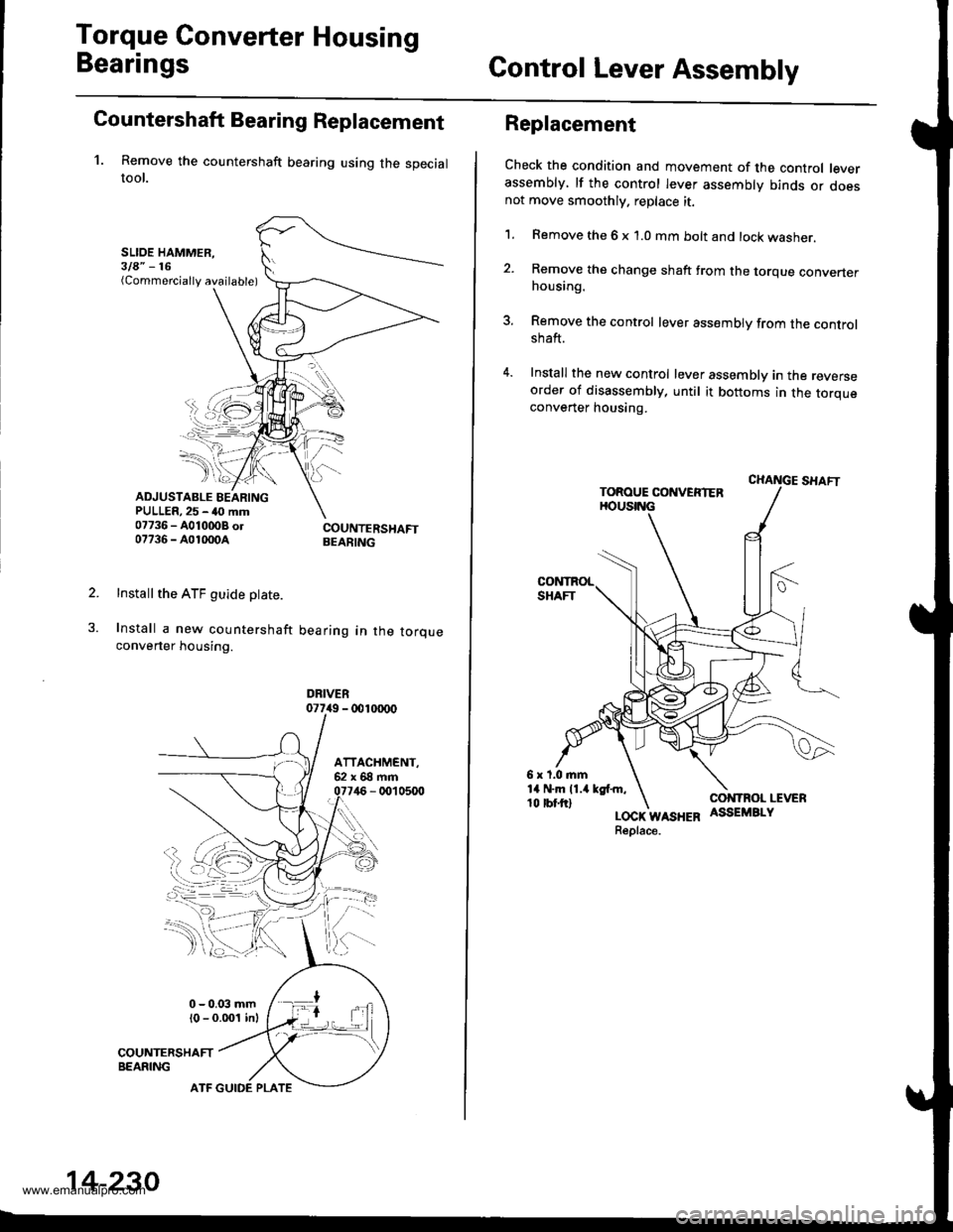
Countershaft Bearing Replacement
1. Remove the countershaft bearing using the specialtool.
SLIOE HAMMER,3la" -16(Commercially available)
ADJUSTABLE BEARINGPULLER,25 - 40 mm07736 - A0100OB ol07736 - A01m0A
Install the ATF guide ptate.
Install a new countershaft
converter housing.
COUNTERSHAFTBEARING
bearing in the torque
DRIVER077i19 - 001m00
14-230
ATF GUIDE PLATE
Replacement
Check the condition and movement of the control leverassembly, lf the control lever assembly binds or doesnot move smoothly. replace it.
1. Remove the 6 x 1.0 mm bolt and lock washer.
2. Remove the change shaft trom the torque converterhousing.
3. Remove the control lever assembly from the controlshaft.
4. Install the new control lever assembly in the reverseorder of disassembly, until it bottoms in the torqueconverter housing.
LOCK WASHERReplace.
www.emanualpro.com
Page 798 of 1395
Description
Hydraulic Flow (cont'dl
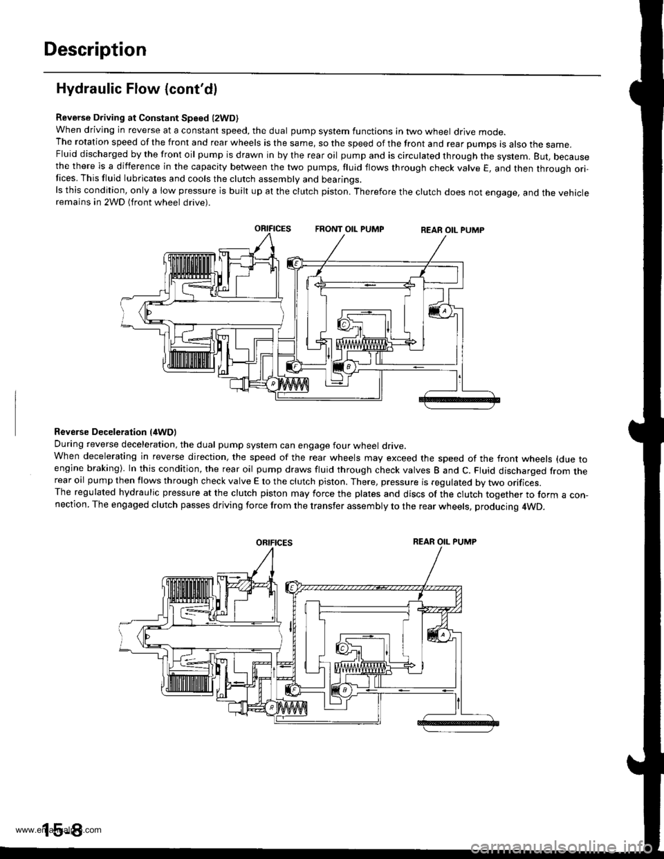
Reverse Driving at Constant Speed l2WD)when driving in reverse at a constant speed, the dual pump system functions in two wheel drive mode.The rotation speed of the front and rear wheels is the same, so the speed of the front and rear pumps is also the same,Fluid discharged by the front oil pump is drawn in by the rear oil pump and is circulated through the system. But, becausethe there is a difference in the capacity between the two pumps, fluid flows through check valve E, and then through ori-Iices. This fluid lubricates and cools the clutch assembly and bearings.ls this condition, only a low pressure is built up at the clutch piston. Therefore the clutch does not engage, and the vehicleremains in 2WD (front wheel drive).
Reverse Deceleration l/tWDl
During reverse deceleration, the dual pump system can engage four wheel drive.When decelerating in reverse direction, the speed of the rear wheels may exceed the speed of the front wheels (due toengine braking). In this condition, the rear oil pump draws fluid through check valves B and C. Fluid discharged from therear oil pump then flows through check valve E to the clutch piston. There, pressure is regulated by two orifices.The regulated hydraulic pressure at the clutch piston may force the plates and discs of the clutch together to form a con,nection. The engaged clutch passes driving force from the transfer assembly to the rear wheels, producing 4WD.
oRtFtcEsREAR OIL PUMP
www.emanualpro.com
Page 835 of 1395
Intermediate Shaft
Reassembly
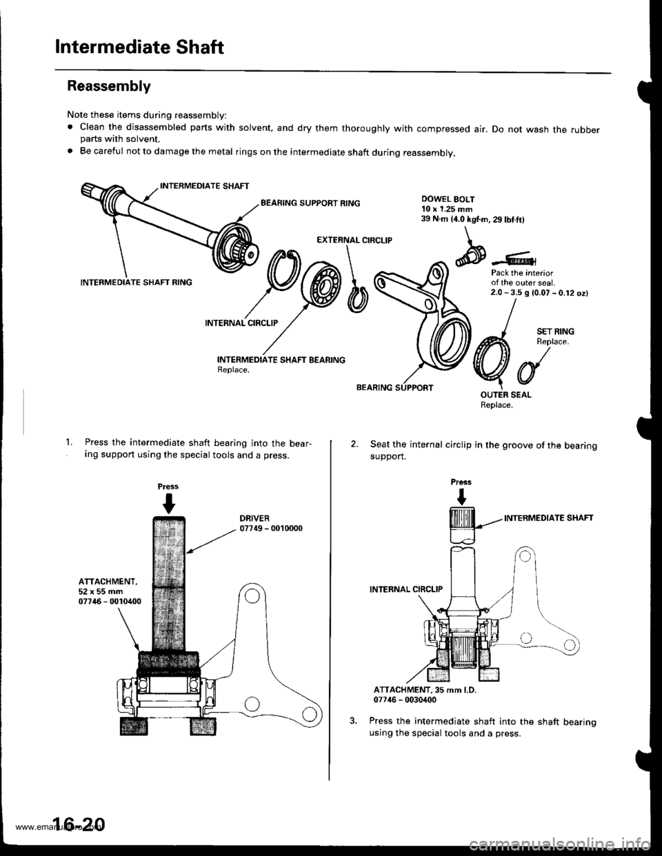
Note these items during reassembly:
. Clean the disassembled parts withparts with solvent.
. Be careful not to damage the metal
solvent, and dry them thoroughly with compressed
rings on the intermediate shaft during reassembly.
air. Do not wash the rubber
BEARING SUPPORT RING
INTERNAL CIRCLIP
Press the intermediate shaft bearing into the bear-ing support using the special tools and a press.
EXTERNAL CIRCLIP
DOWEL EOLT10 x 1.25 mm39 N.m 14.0 kg't m, 29lbf.ft)
Press
I
W--
L!
Pack the interiorof the outer seal.2.0 -3.5 g {0.07 -0.r2 oz}
'L
BEARING SUPPORTOUTER SEA-Replace.
Seat the internal circlip in the groove of the bearingsupport.
INTERMEDIATE SHAFT
ATTACHMENT.35 mm l.D.07746 - 0030400
Press the intermediate shaft into the shaft
using the special tools and a press.
ATTACHMENT,52x55mm07746 - 0010400
INTERMEDIATE SHAFT RING
Prcss
t
16-20
bearing
www.emanualpro.com
Page 866 of 1395
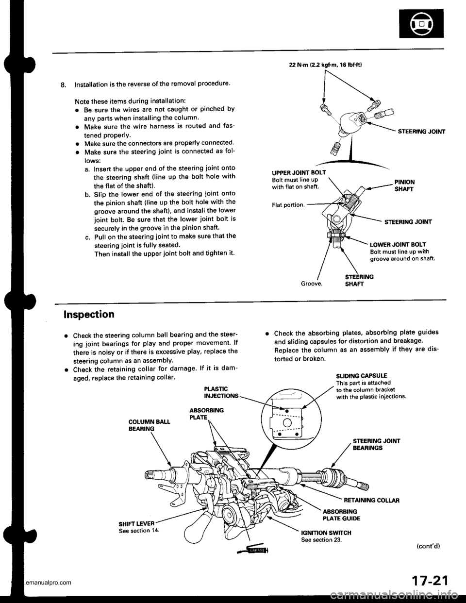
8. Installation is the reverse ofthe removal procedure.
Note these items during installation:
. Be sure the wires are not caught or pinched by
any parts when installing the column.
a Make sure the wire harness is routed and fas-
tened properly.
. Make sure the connectors are properly connected.
. Make sure the steering joint is connected as fol-
lows:
a. lnsert the uDper end of the steering joint onto
the steering shaft (line up the bolt hole with
the flat ot the shaft).
b. Slip the lower end of the steering ioint onto
the Dinion shaft (lins up the bolt hole with the
groove around the shaft). and installthe lower
ioint bolt. Be sure that the lower joint bolt is
securely in the groove in the pinion shaft'
c. Pull on the steering joint to make sure that the
steering joint is JullY seated.
Then install the upper joint bolt and tighten it.
22 N.m (2.2 kgf.m, 16lbt.ftl
UPPER JOINT BOLT
Bolt must Iine uPwith fl6t on shaft.
Flat ponion.
SIEERING JOIMT
STECRING JOINT
LOWER JOINT BOLTBolt must line up withgroove around on shaft,
Inspection
Check the steering column ball bearing and the steer-
ing joint bearings for play and proper movement. lf
there is noisy or if there is excessive play, replace the
steering column as an assemblY
Check the retaining collar for damage. lf it is dam-
aged, replace the retaining collar.
PLASl'tCINJECTIONS
ABSOBBINGPLATE
SHIFT I.EVER
. Check the absorbing plates, absorbing plate guides
and sliding capsules Jor distortion and breakage.
ReDlace the column as an assembly if they are dis-
torted or broken.
SLIDING CAPSUIIThis part is attachedto the column bracketwith the plastic injections.
FETAINING COLLAR
ABSORBINGPLATE GUIDE
|GNMON SWTTCHSee section 23.(cont'd)
17-21
See section 14.
www.emanualpro.com
Page 920 of 1395
Rear Suspension
Hub Bearing Unit Replacement (cont'd)
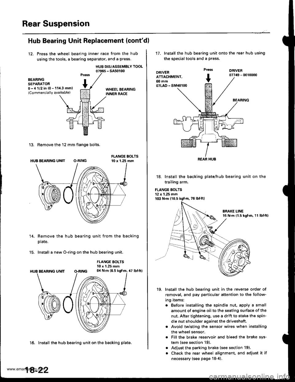
12, Press the wheel bearing inner race from the hub
using the tools, a bearing separator, and a press.
HUB DIS/ASSEMBLY TOOL07965 - SA50100
BEARINGSEPARATOR0 -,t 1/2 in {0 - 11i1.3 mml(Commercially qvailable)
13. Remove the 12 mm flange bolts.
HUB BEARING UN]T O.RING
14. Remove the hub bearing unit from the backing
plate.
15. Install a new O-ring on the hub bearing unit.
FLANGE BOLTS10 x 1.25 mm64 N.m (6.5 kgf.m, 47 lbf.ftl
16. Install the hub bearing unit on the backing plate.
18-22
't7.Install the hub bearing unit onto the rear hub using
the special tools and a press.
DRIVERATTACHMENT,60 mm07LAO - SM40100
Prcss
+
DRIVER07749 - 0010000
BEARING
18. Install the backing plate/hub
trailing arm.
FLANGE BOLTS12 x 1.25 mm103 N.m 110.5 kgf'm,75lbfft)
bearing unit on the
19. Install the hub bearing unit in the reverse order of
removal, and pay particular attention to the follow-
ing items:
. Before installing the spindle nut, apply a small
amount of engine oil to the seating surface of the
nut, After tightening, use a drift to stake the spin-
dle nut shoulder against the driveshaft.
. Avoid twisting the sensor wires when installing
the wheel sensor,
. Fill the brake reservoir and bleed the brake sys-
tem {see section 19).
. Adjust the parking brake (see section 191.
. Check the rear wheel alignment, and adjust it if
necessary (see page 18-4).
REAR HUB
www.emanualpro.com
Page 941 of 1395
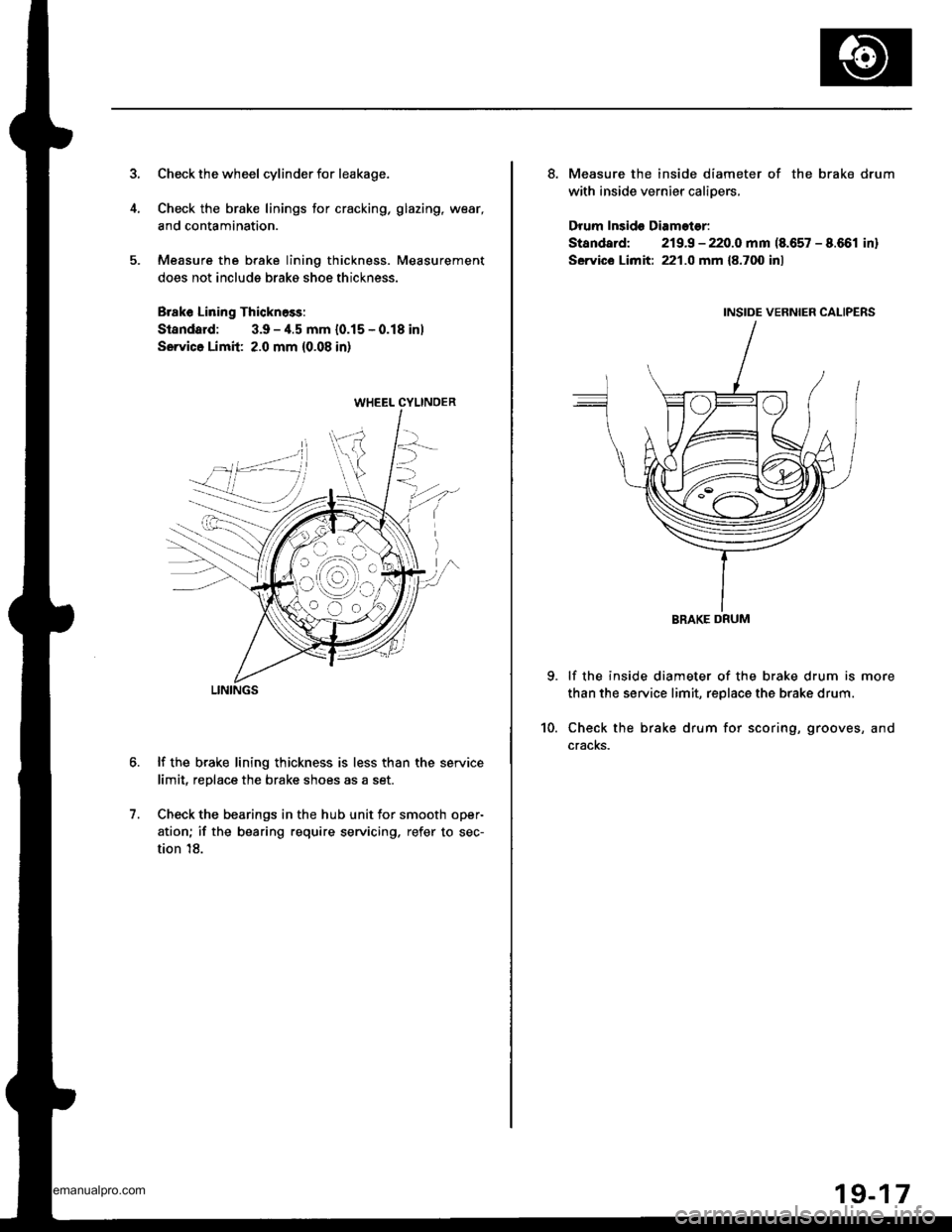
Check the wheel cylinder for leakage.
Check the brake linings for cracking, glazing, wear,
and contamination.
Measure the brake lining thickness. Measurement
does not include brako shoe thickness.
Brake Lining Thicknoss:
Standard: 3.9 -,1.5 mm {0.15 - 0.18 inl
Sorvice Limil: 2.0 mm {0.08 in}
lf the brake lining thickness is less than the service
limit, replace the brake shoes as a set.
Check the bearings in the hub unit for smooth oper-
ation; if the bearing require servicing. refer to sec-
tion 18.
7.
WHEEL CYLINOER
LININGS
8. Measure the inside diameter of the brake drum
with inside vernier calioers,
Drum Insido Diamoter:
Standard: 219.9 - 220.0 mm (8.657 - 8.661 in)
Service Limit: 221.0 mm {8.700 inl
lf the inside diameter of the brake drum is more
than the service limit, replaca the brake drum.
Check the brake drum for scoring, grooves, and
cracKs.
10.
BRAKE DRUM
19-17
www.emanualpro.com