Brake HONDA CR-V 1998 RD1-RD3 / 1.G Owner's Manual
[x] Cancel search | Manufacturer: HONDA, Model Year: 1998, Model line: CR-V, Model: HONDA CR-V 1998 RD1-RD3 / 1.GPages: 1395, PDF Size: 35.62 MB
Page 369 of 1395
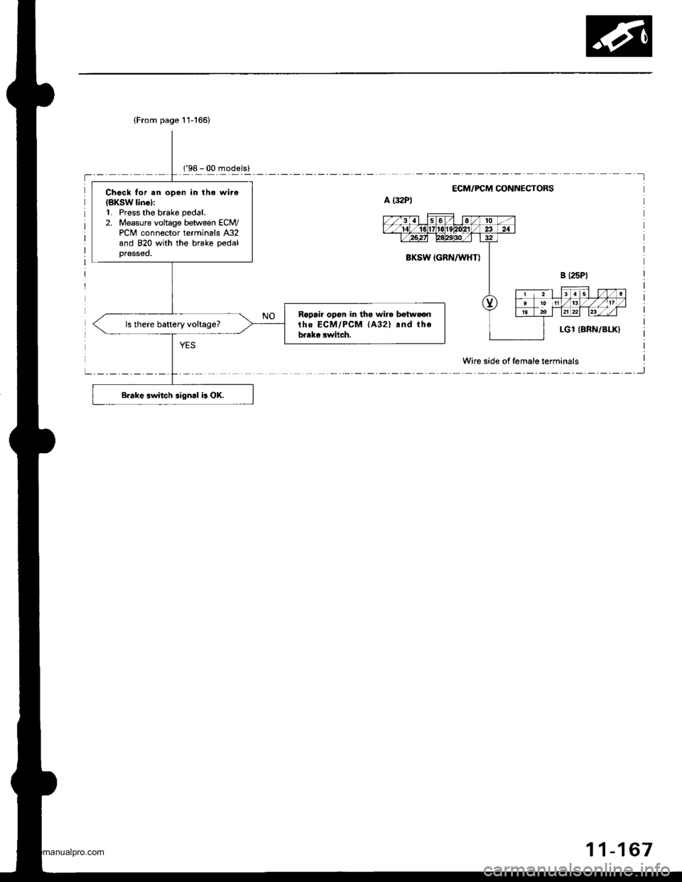
(From page 11-166)
Chock for en open in the wire(BKSW line):1. Press the brake pedal.
2. Measure vohage between ECM/PCM connector terminals A32and 820 with the brake pedalpressed.
Ropair opon in tha wire bstwsonrhe ECM/PCM lA32l rnd thebrako switch.
Brake switch signd b OK.
ECM/FCM OONNECTORS
Wire side of femalo terminals
11-167
www.emanualpro.com
Page 371 of 1395
ldle Speed Setting
Inspoction/Adiustmont
37 modsl:
NOTE:
. Before setting the idle speed, check the following
items:- The MIL has not been reportsd on.- lgnition timing- Spark plugs
- Air cleaner- PCV system
. lcanada) Pull the parking brake lever up. Stan the
engine, then check that the headlights are off.
1. Start the engine. Hold the engine at 3,000 rpm with
no load (in Park or neutral) until the radiator fan
comes on, then let it idle.
Connect a tachometer or a Honda PGM Tester.
Disconnect the 2P connector from the ldle Air Con-
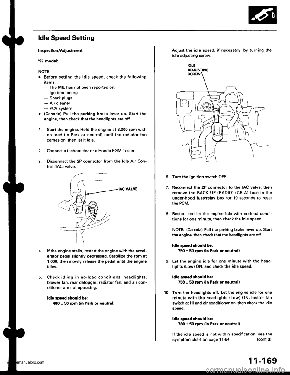
trol (lAC) valve.
IAC VALVE
lf the engine stalls, restart the engine with the accel-
erator pedal slightly depr6ss6d, Stabilize the rpm at
1,000, then slowly release the pedal until the engine
idles.
Check idling in no-load conditions: hsadlights,
blower fan, rear d€fogger, radiator fan, and air con-
ditioner are not operating.
ldle spood should b.:
{80 t 50 rpm {in Park or noutr.ll
IDLE
7.
Adjust the idle sp6ed,
idle adjusting screw.
if necessary, by turning the
Turn the ignition switch OFF.
Reconnect the 2P connector to the IAC valve, then
remove the BACK UP (RAD|Ol (7.5 Al fuse in the
under-hood fuse/rslav box for 10 seconds to reset
the PCM.
Restart and let the engine idle with no-load condi-
tions for one minute, then check the idle speed.
NOTE: (Canadal Pullthe parking brake lever up. Stan
the engine, then check that the headlights are off.
ldlo Ep€ed rhould be:
75O t 50 rpm (in P.rk or noutr.ll
Let the engine idl6 for one minute with the head-
lights (Low) ON, and check th€ idl€ speed.
ldle lpcod 3hould bo:
750 t 50 ]pm (in Park or nautlal)
Turn the headlights off. Let th€ engine idle for one
minute with the headlights (Low) ON, heater fan
switch at Hl and air conditioner on. then check the idle
sDeeo.
ldl. specd should b6:
7d) 1 50 rpm {in Park or nautral}
lf the idle speed is not within specification, see the
symptom chart on page 11-64. (cont'd)
1 1-169
www.emanualpro.com
Page 401 of 1395
Emission Control System
System Description
The emission control system includes, a Three Way
Catalytic Converter {TWC), Positive Crankcase Ventilation
(PCV) svstem and Evaporative Emission (€VAP) Control
system. The emission control system is designed to meet
federal and state emission standards.
Tailpipe Emission
Inspsction
!@ Do not smoke during this procsdura. Keep
any open tlame away from your work area.
1. Start the engine. Hold the engine at 3,000 rpm with
no load (in Park or neutral) until the radiator fan
comes on, then let it idle,
Connect a tachometer.
Check and, if necessary, adjust the idle speed, (see
page 11-169, 170).
Warm up and calibrate the CO meter according to the
meter manufacturer's instructions.
Check idle CO with the headlights, heater blower, rear
window defogger, cooling fan, and air conditioner off.
(Canada) Pull the parking brake lever up. Start the
engine, then check that the headlights are off.
CO meter should indicate 0.1% maximum.
4.
Three Way Catalytic Converter (TWCI
DsscriDtion
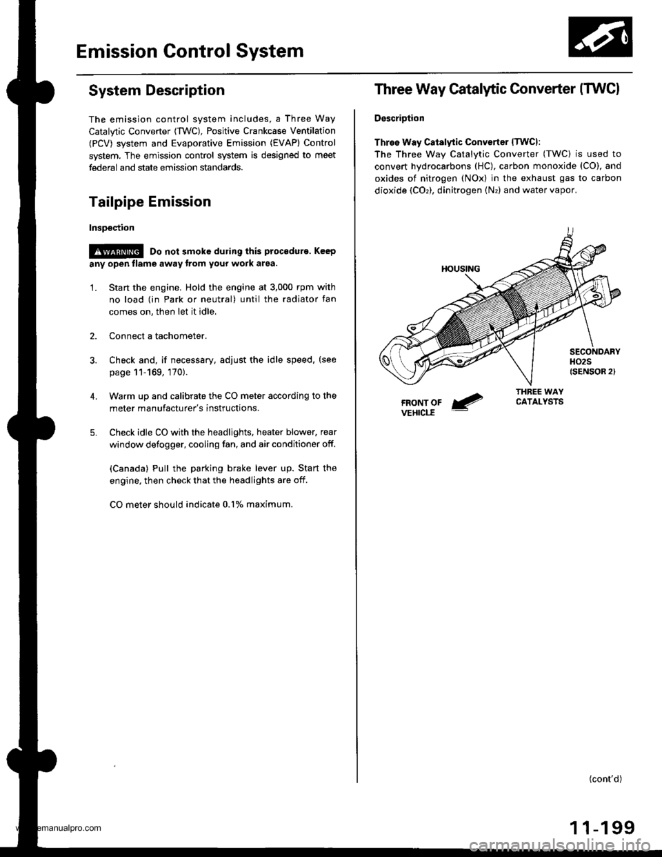
Three Way Catalytic Convertsr lTwcl:
The Three wav Catalvtic Converter (TWC) is used to
convert hydrocarbons (HC), carbon monoxide (CO), and
oxides of nitrogen (NOx) in the exhaust gas to carbon
dioxide (COr), dinitrogen (Nr) and water vapor,
{cont'd)
1 1-199
www.emanualpro.com
Page 432 of 1395
Glutch Master Cylinder
Removal/lnstallation
CAUTION:
. Do not spill brake fluid on the vehicle; it may damage
the paint; if brake tluid does contact the paint. wash
it off immediately with water.
. Plug the end ol the clutch line and leservoir hose
with a shop towel to prevent brake tluid trom coming
out.
The brake fluid may be sucked out through the top
of the master cylinder reservoir with a syringe.
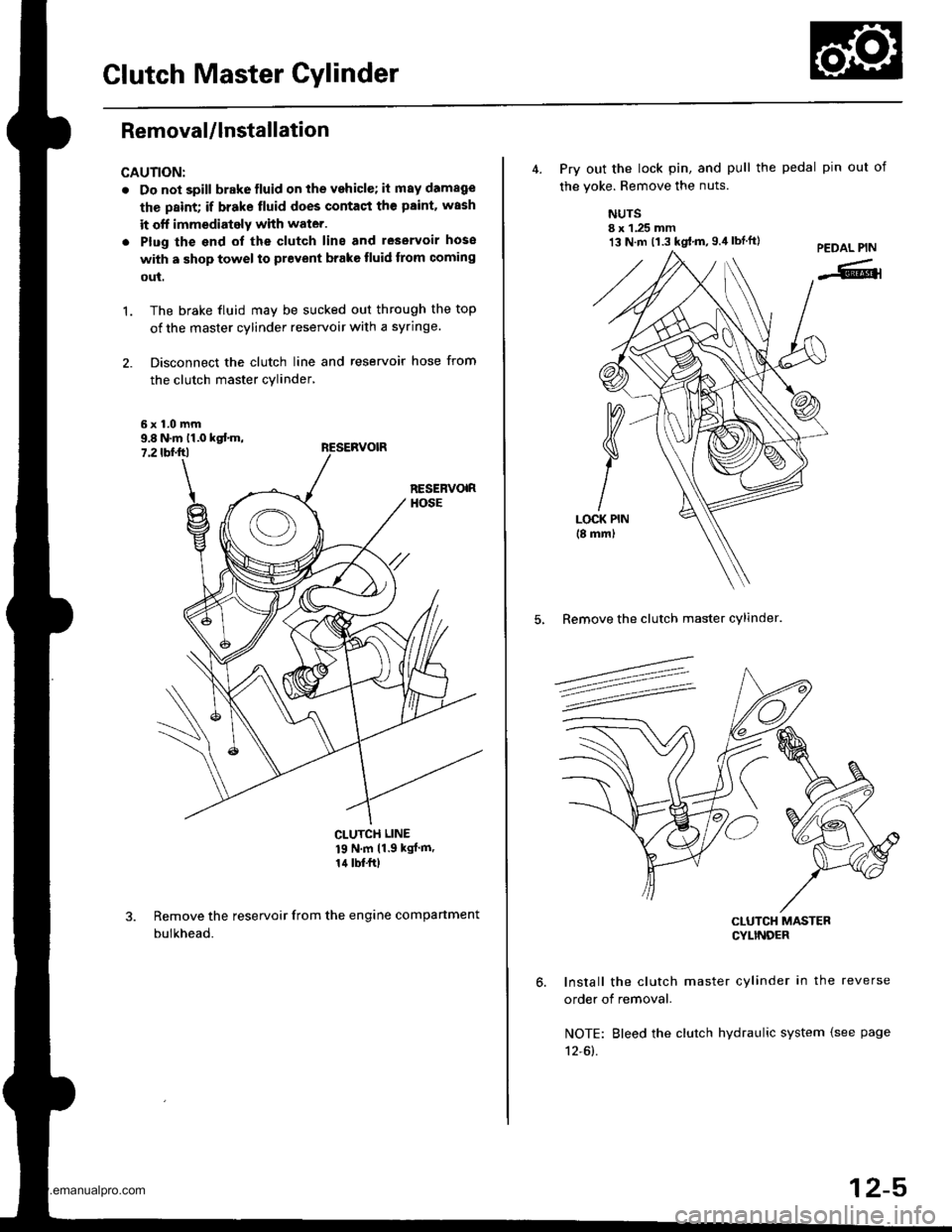
Disconnect the clutch line and reservoir hose from
the clutch master cylinder,
't.
9.8 N.m 11.0 kst m,7.2 tbf.ftl
CLUTCH LINE
19 N'm 11 9 kgJ m'
14 lbf.frl
Remove the reservoir from the engine compartment
bulkhead.
13 N.m t1.3 kgt.m,g.il lbtft)
4. Prv out the lock pin, and pull the pedal pin out of
the voke. Remove the nuts.
NUTSI x 1.25 mm
5, Remove the clutch master cylinder.
CLUTCH MASTERCYLINDEF
Install the clutch master cylinder in the reverse
order of removal.
NOTE: Bleed the clutch hydraulic system {see page
12-61.
12-5
www.emanualpro.com
Page 433 of 1395
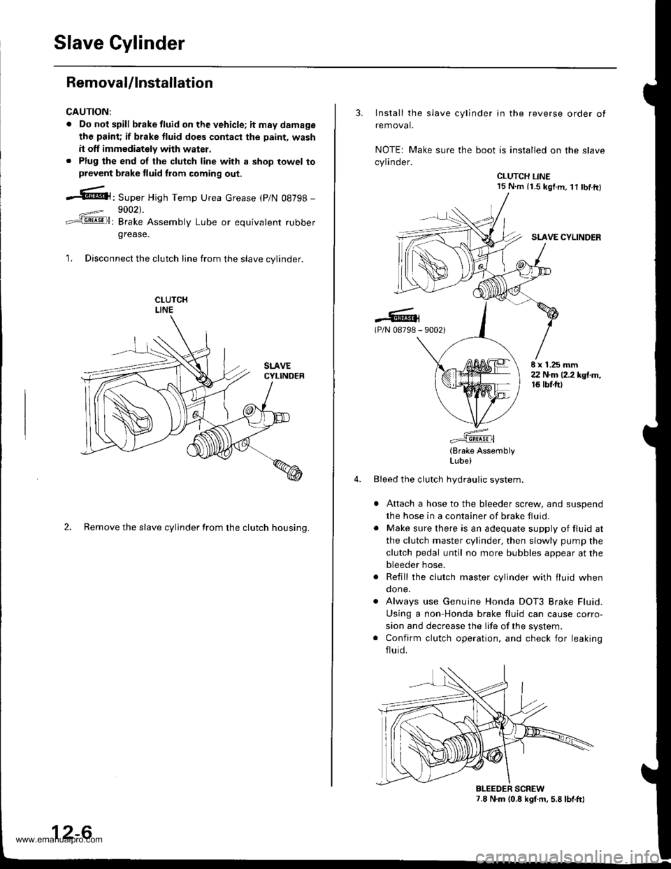
Slave Cylinder
RemovaUlnstallation
CAUTION:
. Do nol spill brake tluid on the vehicle; itmaydamage
the paint; if brake fluid do€s contast the paint, wash
it off immediately with water.. Plug the end of the clutch line with a shop towel toprevcnt brake tluid from coming out.
.6|l,Super High Temp Urea crease (p/N 08798 -
9002).
: Brake Assembly Lube or equivalent rubber
grease.
1. Disconnect the clutch line from the slave cvlinder.
2. Remove the slave cylinder from the clutch housing.
12-6
3. Install the slave cylinder in the reverse order ot
removal.
NOTEr Make sure the boot is installed on the slave
cylinder.
CLUTCH LINE15 N.m (i.S kgf.m, lt tbf.ftl
SLAVE CYLINDER
.-lG(P/N 08798 - 90021
E x 1.25 mm22 N.m (2.2 kgt.m,16 tbtft)
(Brake AssemblyLube)
Bleed the clutch hydraulic system.
Attach a hose to the bleeder screw, and suspend
the hose in a container of brake fluid.
Make sure there is an adequate supply of fluid at
the clutch master cylinder, then slowly pump the
clutch pedal until no more bubbles appear at the
bleeder hose.
Refill the clutch master cylinder with fluid whenqone.
Always use Genuine Honda DOT3 Brake Fluid.
Using a non Honda brake fluid can cause corro-
sion and decrease the life of the system.
Confirm clutch operation, and check for leaking
fluid.
7.8 N.m (0.8 kgf.m. 5.8 lbt.ft)BLEEDER SCREW
www.emanualpro.com
Page 443 of 1395
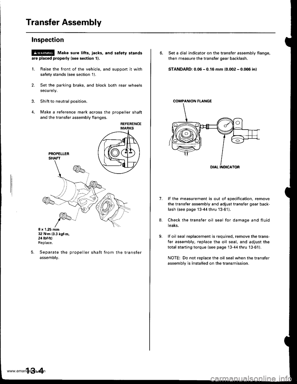
Transfer Assembly
lnspection
@ Make sure tifts, iacks, and satety stands
are placed properly (see section 1).
L Raise the front of the vehicle, and support it with
safety stands (see section 1).
2. Set the parking brake, and block both rear wheels
securely.
3. Shift to neutral oosition.
4. Make a reference mark across the DroDeller shaft
and the transfer assembly flanges,
REFERENCE
8 x 1.25 mm32 N.m (3.3 kg{.m.24 rbf.ftlReplace.
Separate the propeller shaft from the transfer
assemDty.
5.
13-4
6. Set a dial indicator on the transfer assembly flange,
then measure the transfer gear backlash.
STANDARD: 0.06 - 0.16 mm (0.002 - 0.006 in)
COMPAf{ION FI-ANGE
1.lf the measurement is out of specification, remove
the transfer assembly and adjust transfer gear back-
lash (see page 13-44 thru '13-61).
Check the transfer oil seal for damage and fluid
teaKs.
lf oil seal replacement is required, remove the trans-
fer assembly, replace the oil seal, and adjust the
total starting torque (see page 13-44 thru 13-61).
NOTE: Do not replace the oil seal when the transfer
assembly is installed on the transmission.
www.emanualpro.com
Page 444 of 1395
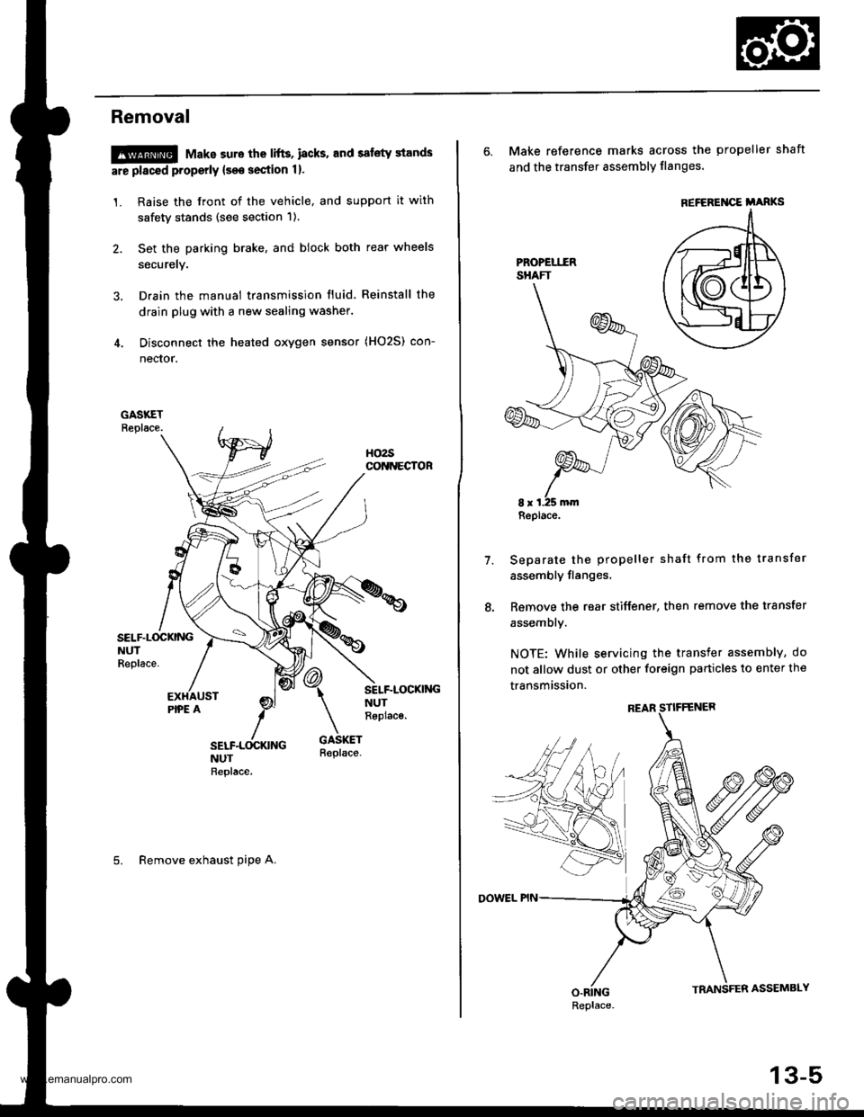
Removal
!@@ Make sure the lifts, i8cks. and safety stands
are placed properly {see section 1}.
1. Raise the front of the vehicle, and support it with
safety stands (see section 1).
2. Set the parking brake, and block both rear wheels
securely.
3. Drain the manual transmission fluid Reinstall the
drain plug with a new sealing washer.
4. Disconnect the heated oxygen sensor (HO2S) con-
nector.
SELF.L(rcKNGNUTReplace.
SELF-LOCKI'{GNUTReplac€.
5. Remove exhaust oipe A.
6. Make reference marks across the propeller shaft
and the transfer assembly flanges'
Separate the propeller shaft from the transfer
assembly flanges,
Remove the rear stiffener, then remove the transfer
assembly.
NOTE: While servicing the transfer assembly, do
not allow dust or other foreign particles to enter the
transmission.
7.
REFEREI{CE i'ARKS
Replace.
Replace.
13-5
www.emanualpro.com
Page 446 of 1395
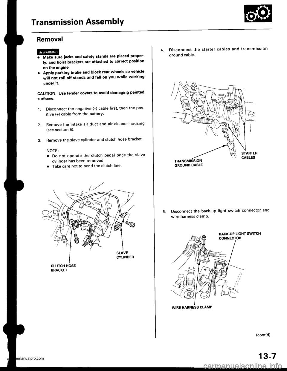
Transmission AssemblY
Removal
@FMak. sw. iack" and safety stands are placed propel-
ly, and hoist brackets are attached to collect position
on the engine,
. Apply parking brake and block rear wheels so vehicle
will not roll off stands and lall on you while working
under it.
CAUTION: Use fender covers to avoid damaging painted
surfaces.
1. Disconnect the negative {-) cable first, then the pos-
itive (+) cable from the batterY.
2. Remove the intake air duct and air cleaner houslng
(see section 5).
3. Remove the slave cylinder and clutch hose bracket'
NOTE:
. Do not operate the clutch pedal once lhe slave
cvlinder has been removed.
. Take care not to bend the clutch line.
4. Disconnect the
ground cable.
starter cables and transmission
TRANSMISSIONGROUND CABLE
Disconnect the back-up light switch connector and
wire harness clamP.
(cont'd)
13-7
WIRE HARNESS CLAMP
www.emanualpro.com
Page 534 of 1395
Description
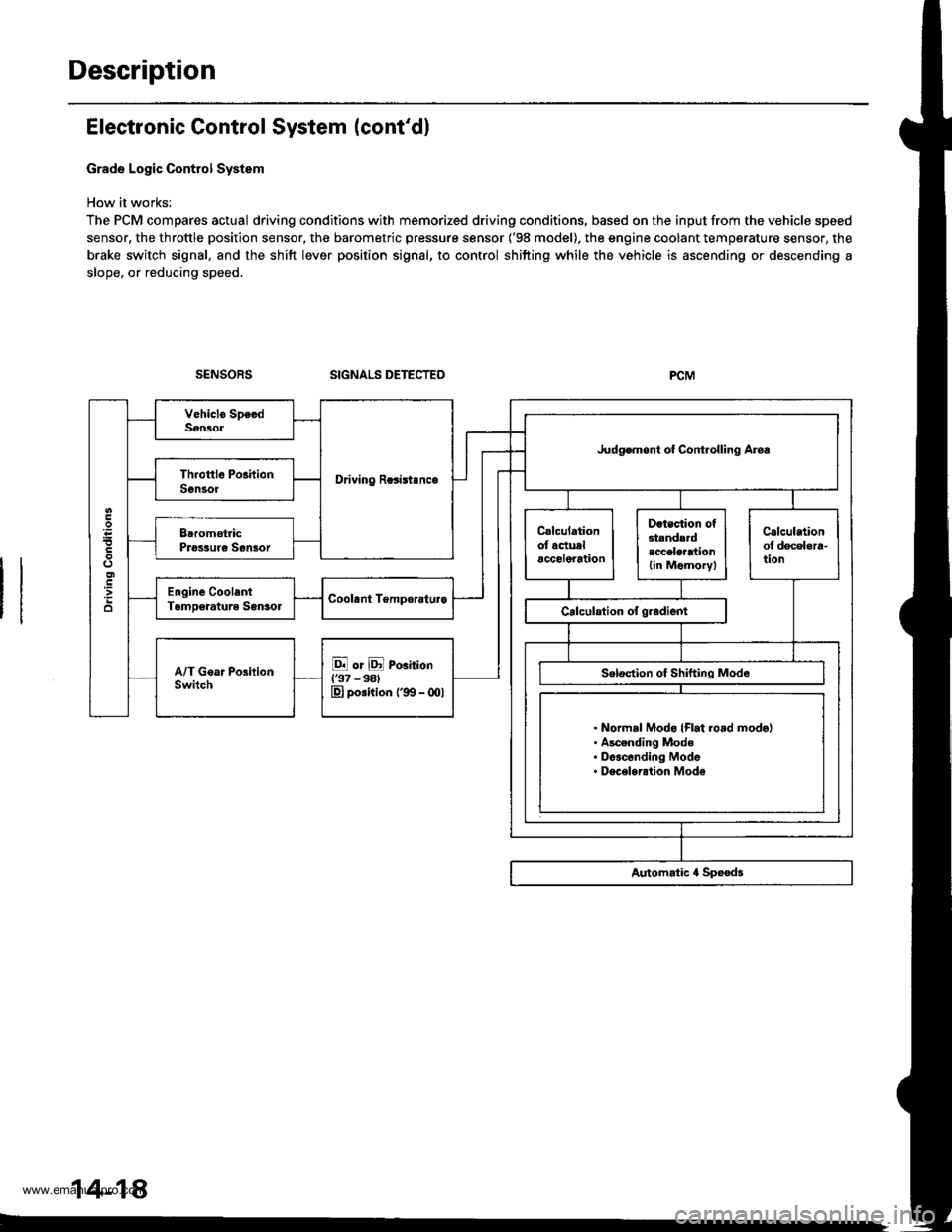
Electronic Control System (cont'dl
Grade Logic Control System
How it works:
The PCM compares actual driving conditions with memorized driving conditions, based on the input from the vehicle speed
sensor, the throttle position sensor, the barometric pressure sensor ('98 model). the engine coolant temperature sensor, the
brake switch signal, and the shift lever position signal, to control shifting while the vehicle is ascending or descending a
slope, or reducing speed.
SIGNALS DETECTED
Driving Rcsisl.nce
Judgemont ot Controlling Aroa
. Normal Modo {Flrt ro.d mode}. Ascending Mode. Deacending Mode. Deceleration Mode
14-14
www.emanualpro.com
Page 536 of 1395
Description
Electronic Control System (cont'd)
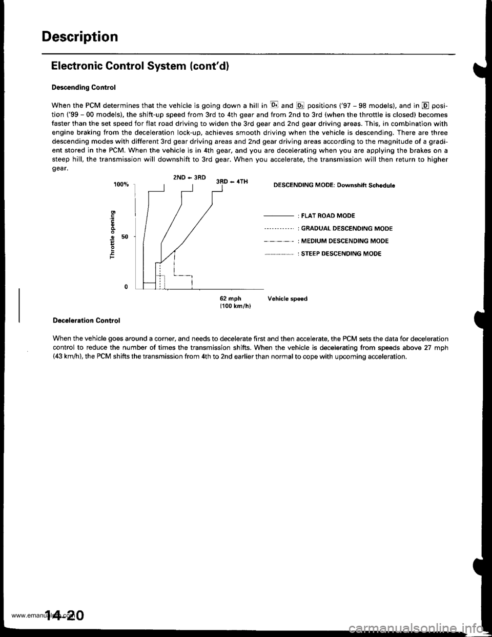
Descending Control
When the PCM determines that the vehicle is going down a hill in E and @ positions ('97 - 98 models). and in @ posi-
tion {'99 - 00 models), the shitt-up speed from 3rd to 4th gear and from 2nd to 3rd (when the throttle is closed) becomes
faster than the set speed for flat road driving to widen the 3rd gear and 2nd gear driving areas. This, in combination with
engine braking from the deceleration lock-up, achieves smooth driving when the vehicle is descending. There are three
descending modes with different 3rd gear driving areas and 2nd gear driving areas according to the magnitude of a gradi-
ent stored in the PCM. When the vehicle is in 4th gear, and you are decelerating when you are applying the brakes on a
steep hill, the transmission will downshift to 3rd gear, When you accelerate, the transmission will then return to higher
gear.
2ND - 3RD 3RD - 4TH
o50
F
DESCENDING MODE: Downshift Schodule
- : FLAT ROAD MODE
----'-----' I GRADUAL DESCENDING MODE
- - - - - : MEDIUM OESC€NOING MODE
. . ... : STEEP DESCENDING MODE
62 mph Vehicle sp€ed1100 km/hl
Deceleration Control
When the vehicle goes around a corner, and needs to decelerate first and then accelerate, the PCM sets the data for deceleration
control to reduce the number of times the transmission shifts. When the vehicle is decelerating from speeds above 27 mph(4i| km,ih), the PCM shifts the transmission from 4th to 2nd earlier than normal to cope with upcoming acceleration,
14-20
www.emanualpro.com