Coil HONDA CR-V 1998 RD1-RD3 / 1.G Owner's Manual
[x] Cancel search | Manufacturer: HONDA, Model Year: 1998, Model line: CR-V, Model: HONDA CR-V 1998 RD1-RD3 / 1.GPages: 1395, PDF Size: 35.62 MB
Page 717 of 1395
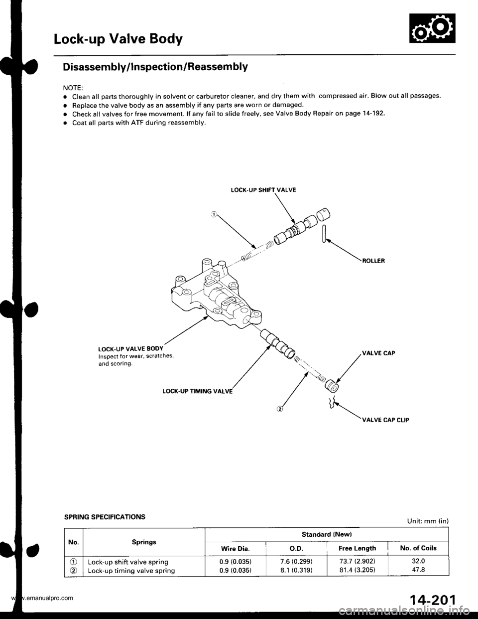
Lock-up Valve Body
Disassembly/lnspection/Reassem bly
NOTE:
. Clean all parts thoroughly in solvent or carburetor cleaner, and dry them with compressed air. Blow out all passages.
. Replace the valve body as an assembly if any parts are worn or damaged.
. Checkall valvesforfree movement. lf anyfailto slide freely, seeValve Body Repairon page 14-192.
. Coat all parts with ATF during reassembly.
LOCK.UP SHIFT VALVE
\/'
\-.xlO
@-tr
, ^ ,As'. \"o...*
LOCK-UP VALVE EODY
Inspect lor wear, scratches,
and scoring.
VALVE CAP
\uo.*"or".,,
LOCK-UP TIMING VAL
SPRING SPECIFICATIONSUnit: mm (in)
No.SpringsStandard lNewl
Wire Dia.o.D.Fle€ LengthNo. of Coils
O(Lock up shift valve spring
Lock-up timing valve spring
0.9 (0.035)
0.9 (0.035)
7.6 (0.299)
8.1 (0.319)
73.1 t2.902),
81.4 (3.205)
32.0
47 .8
14-201
www.emanualpro.com
Page 954 of 1395
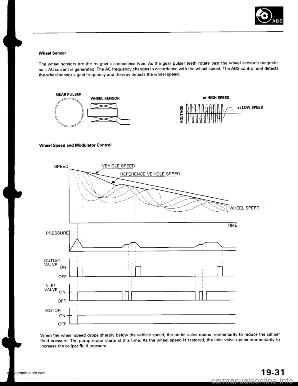
Wheel Sensor
The wheel sensors are the magnetic contactless type. As the gear pulser teeth rotate past the wheel sensor's magnetic
coil, AC current is generated. The AC frequency changes in accordance with the wheel speed. The ABS control unit detects
the wheel sensor signal frequency and thereby detects the wheel speed
at LOW SPEED
wheel Sp€od and Modulatot Control
VEHICLE SPEED
VEHICLE SPEED
WHEEL SPEED
PRESSU
OUTLETVALVE ON
OFF
INLETVALVE ON
OFF
MOTOR
ON
OFF
When the wheel speed drops sharply below the vehicle speed, the outlet valve opens momentarily to reduce the caliper
fluid pressure. The pump motor starts at this time. As the wheel speed is restored. the inlet valve opens momentarily to
increase the caliDer fluid oressure.
F
GEAR PULSER
19-31
www.emanualpro.com
Page 1125 of 1395
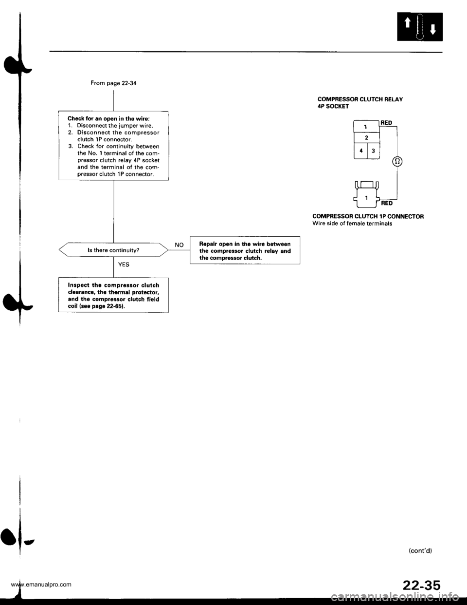
COMPRESSOR CLUTCH RELAYilP SOCKET
COMPRESSOR CLUYCH lP CONNECTORWire side of lemale terminals
-_-l RED
tr-=--l II
I.TT
@
I
$"f Ii 1 __---.1
1___J.RED
I
I
+
Ftom page 22-34
Check for an open in the wire:1. Disconnect the jumper wire.2. Disconnect the compressorclutch 1P connoctor.3. Check for continuity betweenthe No. 1 terminal of the com-pressor clutch relay 4P socketand the terminal ol the com-pressor clutch 1P connector.
Repair open in the wire betweenthe comp.e3sor clutch relay andthe comprsssor clutch.
Inspect tha compreslor clutchclearanco, the thormal protector,
and ths comDrg$or clutch tioldcoil lsee page 22-65).
I
I
.l-(cont'd)
www.emanualpro.com
Page 1154 of 1395
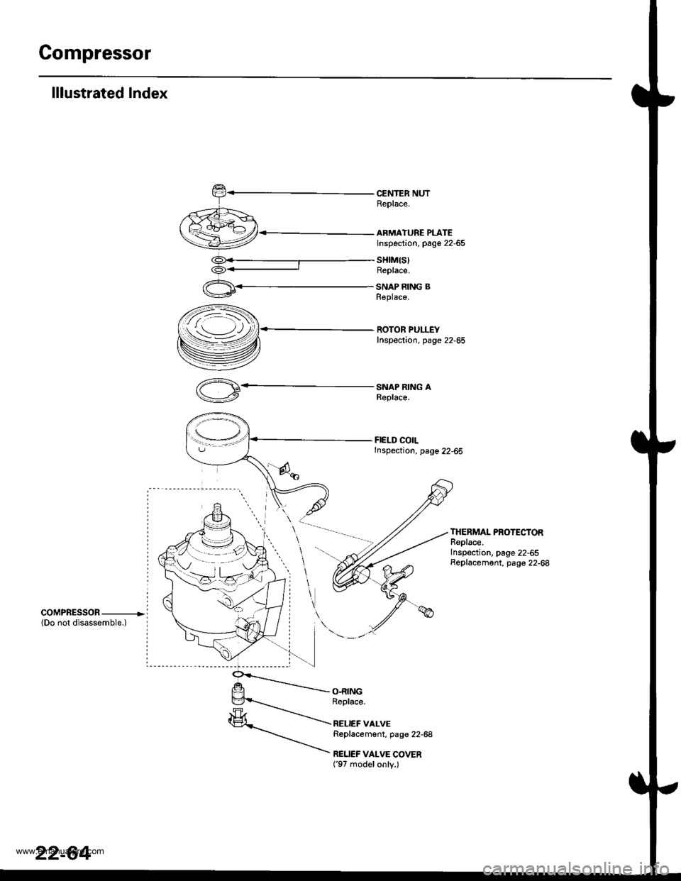
Gompressor
lllustrated Index
CENTER NUTReplace.
ARMATURE PLATEInspection, page 22-65
sHtM{s)Replace.
SNAP RING BReplace.
ROTOR PULLEYInspection. page 22-65
SNAP RING AReplace.
FIELD COILInspection, page 22-65
THERMAL PROTECTORReplace.Inspection, page 22-55Replacement, page 22-68
coMPRESSOR ----------------(Do not disassemble.)
O.RINGRoplace.
RELIEF VALVEReplacement, page 22-68
RELIEF VALVE COVER('97 modelonly.)
22-64
www.emanualpro.com
Page 1155 of 1395
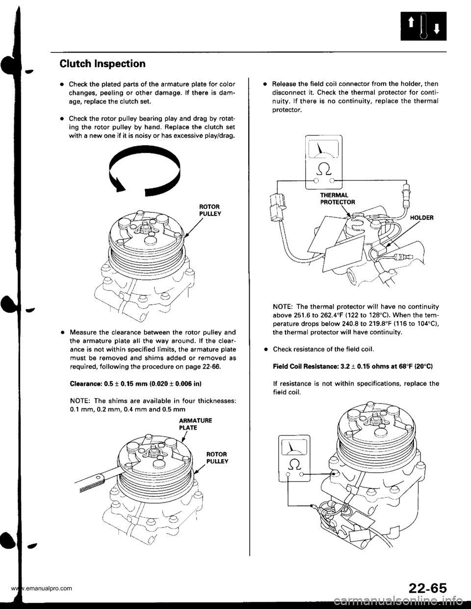
Clutch Inspection
Check the plated parts of the armature plate for color
changes, peeling or other damage. lf there is dam-
age, replace the clutch set.
Check the rotor pulley bearing play and drag by rotat-
ing the rotor pulley by hand. Replace the clutch set
with a new one if it is noisy or has excessive play/drag.
Measure the clearance between the rotor pulley and
the armature plate all the way around. lf the clear-
ance is not within specified limits, the armature plate
must be removed and shims added or removed as
required, following the procedure on page 22-66.
Cloarance: 0.5 t 0.15 mm {0.020 t 0.q)6 in)
NOTE: The shims are available in four thicknesses:
0.1 mm. 0.2 mm. 0.4 mm and 0.5 mm
ABMATUBE
ROTOR
. Release the field coil connector from the holder, then
disconnect it. Check the thermal protector for conti-
nuity, lf there is no continuity, replace the thermal
prorecror.
NOTE: The thermal protector will have no continuity
above 251.6 to 262.4"F 1122 to 128"C). When the tem-perature drops below 240.8 to 219.8"F (116 to 104'C),
the thermal protector will have continuity.
Check resistance of the field coil.
Field Coil Resistance: 3.2 i 0.15 ohms at 68"F {20'C)
lf resistance is not within specifications, replace the
field coil.
22-65
www.emanualpro.com
Page 1157 of 1395
l-
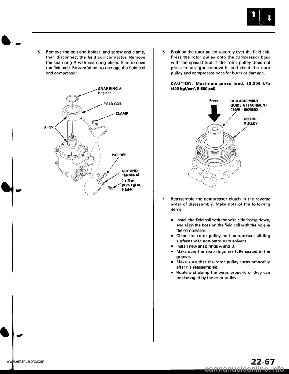
5. Remove the bolt and holder, and screw and clamp.
then disconnect the field coil connector. Remove
the snap ring A with snap ring pliers, then remove
the field coil. Be careful not to damage the field coil
and comoressor.
FIELD COIL
CLAMP
HOLDER
GROUNDTERMINAL
7,a N.m
10.75 kgt'm,5 tbt ftl
6. Position the rotor pulley squarely over the field coil.
Press the rotor pulley onto the compressor boss
with the special tool. lf the rotor pulley does not
press on straight, remove it, and check the rotor
pulley and compressor boss for burrs or damage.
CAUTION: Maximum pre3s load: 39,200 kPa
(400 kgf/cm,, 5,690 psi)
Press
+
HUB ASSEMBLYGUIDE ATTACHMENT07966 - 6920500
7.
ROTORPULLEY
Reassemble the comDressor clutch in the reverse
order of disassembly. Make note of the following
rrems.
Install the field coil with the wire side facing down,
and align the boss on the tield coil with the hole in
the compressor.
Clean the rotor pulley and compressor sliding
surfaces with non-oetroleum solvent.
lnstall new snap rings A and B.
Make sure the snap rings are fully seated in the
groove.
Make sure that the rotor pulley turns smoothly
after it's reassembled.
Route and clamp the wires properly or they can
be damaged by the rotor pulley.
a
a
www.emanualpro.com
Page 1158 of 1395
Compressor
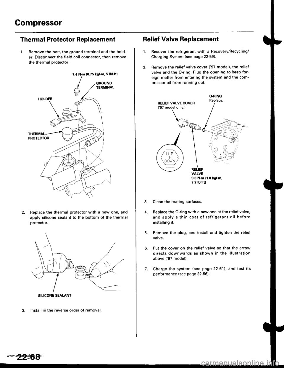
Thermal Protector Replacement
1. Remove the bolt, the ground terminal and the hold-
er. Disconnect the field coil connector. then remove
the thermal Drotector.
7.4 N.m (0.75 kgrf.m,5lbf ftl
GROUNDTERMINAL
ReDlace the thermal protector with a new one, and
apply silicone sealant to the bottom of the thermal
orotector,
3. lnstall in the reverse order of removal.
SILICONE SEALANT
22-68
Relief Valve Replacement
l.Recover the refrigerant with a Recovery/Recycling/
Charging System (see page 22-59).
Remove the relief valve cover ('97 model), the relief
valve and the O-ring. Plug the opening to keep for-
eign matter from entering the system and the com-
pressor oil from running out.
O.RINGReplace.
RELIEFVALVE9.8 N.m {1.0 hgf.m,7.2 rbr.ftl
Put the cover on the relief valve so that the arrow
directs downwards as shown in the illustration
above ('97 model).
Clean the mating surfaces.
Replace the O-ring with a new one at the relief valve,
and apply a thin coat of refrigerant oil before
installing it.
Remove the plug. and install and tighten the relief
valve.
7. Charge the system (see page 22-61), and test its
performance (see page 22-561r.
www.emanualpro.com