Power steering pump HONDA CR-V 1998 RD1-RD3 / 1.G Owner's Manual
[x] Cancel search | Manufacturer: HONDA, Model Year: 1998, Model line: CR-V, Model: HONDA CR-V 1998 RD1-RD3 / 1.GPages: 1395, PDF Size: 35.62 MB
Page 875 of 1395
Power Steering Pump
Reassembly (cont'dl
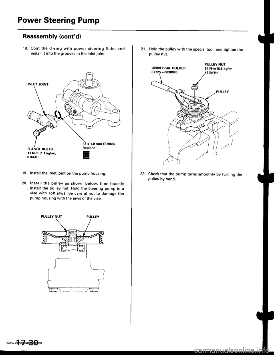
'18. Coat the O-ring wjth power steering fluid, andinstall it into the grooves in the inlet joint.
FLANGE BOLTS11 N.m 11.1 kgf.m,8 rbf.ft)
'13 x '1.9
Replace.r
E
19.
20.
Install the inlet joint on the pump housing.
Install the pulley as shown below. then loosely
install the pulley nut. Hold the steering pump in avise with soft jaws. Be careful not to damage thepump housing with the jaws of the vise.
17-30
21. Hold the pulley with the speciat toot, and tighten thepulley nut.
Check that the pump turns smoothly by turning thepulley by hand.
www.emanualpro.com
Page 877 of 1395
Power Steering Gearbox
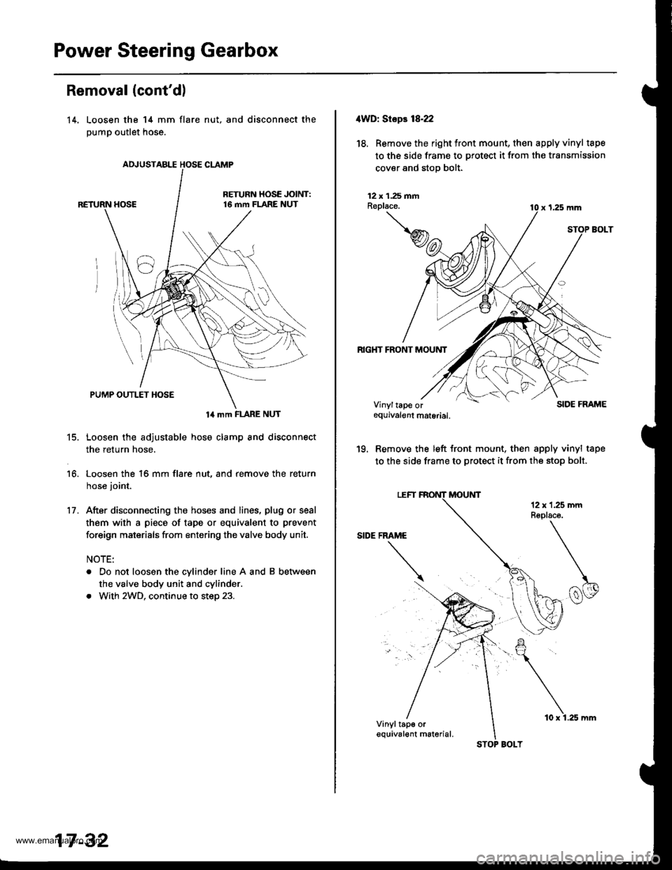
AN'USTABLE HOSE CLAMP
Removal (cont'dl
14. Loosen the 14 mm flare
pump outlet hose.
nut, and disconnect the
14 mm FLARE NUT
15. Loosen the adjustable hose clamp and disconnect
the return hose,
16. Loosen the 16 mm flare nut, and remove the return
hose joint.
17. After disconnecting the hoses and lines, plug or seal
them with a piece of tape or equivalent to prevent
foreign maisrials from entering the valve body unit.
NOTE:
. Do not loosen the cylinder line A and B between
the valve body unit and cylinder.
. With 2WD, continue to step 23.
17 -32
STOP BOLT
10 x 1.25 mm
4WD: Stepr 18-22
18. Removethe right tront mount, then apply vinyl tape
to the side frame to protect it from the transmission
cover and stop bolt.
12 x 1.25 fiiAReplace.
RIGHT FRONT MOUNT
x 1,25 mm
SIDE FRAME
'19. Remove the left front mount, then apply vinyl tape
to the side frame to protect it from the stop bolt.
Vinyltape orequivalgnt material.
Vinyltap€ orequival€nt m6terial.
www.emanualpro.com
Page 897 of 1395
Power Steering Gearbox
Installation (cont'd)
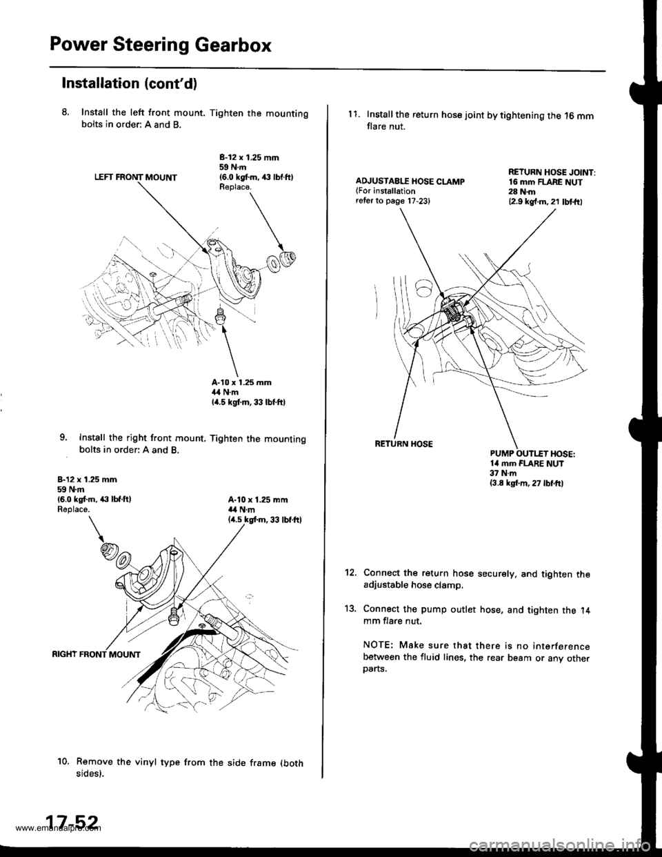
8, Install the left front mount. Tighten the mountingbolts in order: A and B.
LEFT FRONT MOUNT
B-12 x 1,25 mm59Nm(6.0 kgtm,,€ lbl.ftlReplaca.
9. Instsll the right front mount, Tighten the mountingbolts in order: A and B.
B-12 x 1.25 mm59 N.m16.0 ks[.m, ,|:| lbf.ftlReplace.
A-10 x 1.25 mm4,1 N.mla.s kgt m, 33 lbf.ft)
A-10 x 1.25 mma,a N.m
10. Remove the vinyl type from the side frame (both
sides).
17-52
11. Installthe return hose joint by tightening the 16 mmflare nut.
AD.'USTAB[T HOSE CLAMP(For installationreter to page 17,23)
RETURN HOSE JOINT:16 mm FLARE NUT28 N.m12.9 kg{.m.21 lbt{t)
14 mm FLARE NUT37 N.m(3.8 ksf.m, 27 lbl'frl
't2.
13.
Connect the return hose securely. and tighten theadjustable hose clamp.
Connect the pump outlet hose, and tighten the l4mm flare nut.
NOTE: Make sure that there is no interferencebetween the fluid lines, the rear beam or any otherparts.
www.emanualpro.com
Page 1152 of 1395
Compressor
Replacement
lf the compressor is marginally operable. run the
engine at idie speed, and let the air conditioner
work for a few minutes. then shut the engine off.
Disconnect the negative cable from the battery.
Recover the refrigerant with a recovery/recycling/
charging station (see page 22-59).
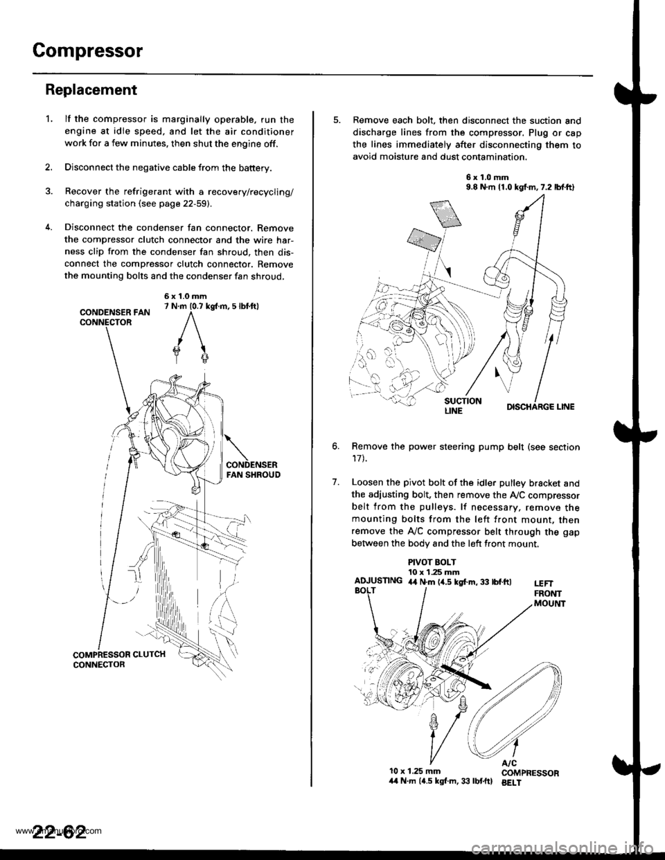
Disconnect the condenser fan connector. Remove
the compressor clutch connector and the wire har-
ness clip from the condenser fan shroud, then dis-
connect the compressor clutch connector. Remove
the mounting bolts and the condenser fan shroud,
CONDENSER FANCONNECTOR
6x1.0mm7 N.m 10.7 kg{.m, 5 lbl.ftl
'L
2.
5. Remove each bolt, then disconnect the suction and
discharge lines from the compressor. Plug or cap
the lines immediately after disconnecting them to
avoid moisture and dust contamination,
6x1.0mm9.8 N.m 11.0 kgf.m,7.2 lbf.ft)
DISCHARGE LINE
Remove the power steering pump belt (see section
17t.
Loosen the pivot bolt of the idler pulley bracket and
the adiusting bolt, then remove the Ay'C compressor
belt from the pulleys. lf necessary, remove themounting bolts from the left front mount, thenremove the A,/C compressor belt through the gap
between the bodv and the left front mount.
6.
7.
PIVOT BOLT10 x 1.25 mmAIUUSTING 4,t N.m (4.5 kgf.m, 33 tbf.ftlt€FTFRONTMOUltlT
10x 1.25 mm COMPRESSOR/t4 N.m (4.5 kgl.m,33 lbtftl BELI
LINE
www.emanualpro.com
Page 1153 of 1395
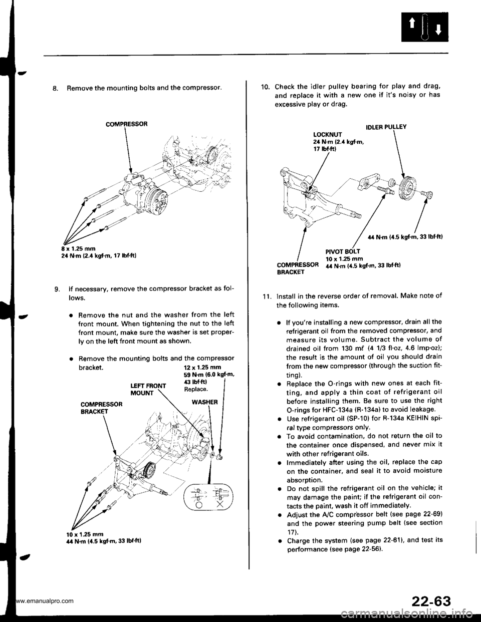
8. Remove the mounting bolts and the compressor.
E x 1.25 mm2a N.m (2.,1kgf.m, l7 lbl.ft)
lf necessary, remove the compressor bracket as fol-
lows.
. Remove the nut and the washer from the left
front mount. When tightening the nut to the left
front mount, make sure the washer is set proper-
ly on the left front mount as shown.
. Remove the mounting bolts and the compressor
bracket.
q
12 x 1.25 mm
59 N.m (6.0 kgt'm,
10 x 1,25 mmart N.m (4.5 kgf'm, 33 lbfftl
11.
10. Check the idler pulley bearing for play and drag,
and replace it with a new one if it's noisy or has
excessive play or drag.
lnstall in the reverse order of removal. Make note of
the following items,
. lf you're installing a new compressor, drain all the
reJrigerant oil from the removed compressor, and
measure its volume. Subtract the volume of
drained oil trom 130 m/ 14 U3 fl'o2,4.6 lmp'oz);
the result is the amount of oil you should drain
lrom the new compressor (through the suction fit-
trngl.
. Replace the O-rings with new ones at each fit-
ting, and apply a thin coat o{ refrigerant oil
before installing them. Be sure to use the right
O-rings for HFC-134a (R-134a) to avoid leakage.
. Use refrigerant oil (SP-10) for R-134a KEIHIN spi-
ral type compressors only.
. To avoid contamination, do not return the oil to
the container once dispensed, and never mix it
with other refrigerant oils.
. lmmediately after using the oil, replace the cap
on the container. and seal it to avoid moisture
aDsorprlon.
. Do not spill the refrigerant oil on the vehicle; it
may damage the paint; if the retrigerant oil con-
tacts the Daint, wash it off immediately.
. Adjust the Ay'C compr'essor b€lt (see psge 22-69)
and the power steering pump belt {see section
17t.
. Charge the system (see page 22-611, and test its
performance (see page 22-56]-.
IDLER PULLEY
+r N.m 14.5 kgt m,33lbf ftl
PIVOT BOLT10 x 1.25 mmir4 N.m {4.5 kgt m, 33 lbl'ft}BBACKET
www.emanualpro.com
Page 1172 of 1395
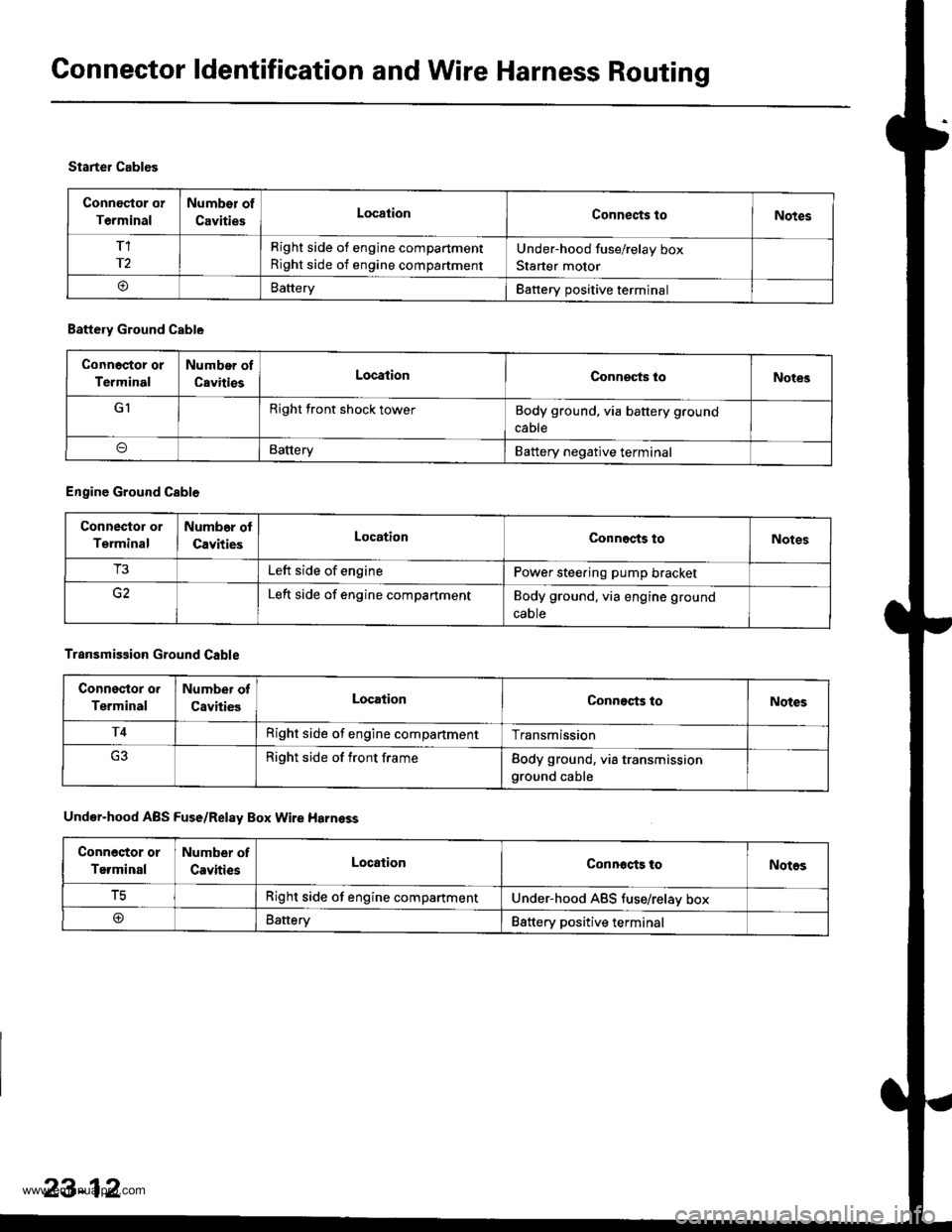
Connector ldentification and Wire Harness Routing
Connoctor or
Terminal
Number of
CavitiesLocationConnects toNotes
T1
r2
Right side of engine compartment
Right side of engine compartment
Under-hood fuse/relay box
Starter motor
oBatteryBattery positive terminal
Starter Cables
Battery Ground Cable
Connoctor or
Terminal
Number of
CavitiesLocationConneqts loNotes
GIRight front shock towerBody ground, via battery ground
cable
BatteryBattery negative terminal
Engine Ground Cable
Connector or
Terminal
Numb6r ol
CavitiesLocationConnects toNotes
T3Left side of enginePower steering pump bracket
Left side of engine compartmentBody ground. via engine ground
caote
Transmission Ground Cable
Connsstor o.
Terminal
Number of
CavitiesLocationConnects toNotes
T4Right side of engine compartmentTransmission
Right side of front frameBody ground, via transmissionground cable
Under-hood ABS Fuse/Relay Box Wire Harnsss
Conn6stor or
Terminal
Number of
CavitiesLocationConnocts toNotos
tcRight side of engine compartmentUnder-hood ABS tuse/relav box
@Battery88ttery positive terminal
23-12
www.emanualpro.com
Page 1206 of 1395

Ground Distribution
Ground-to-Component(sl Index
GroundWire Color
G2
G3
G 10'l
G201
G202
G351
BLIVRED
BRN
BLK
BLK
BRN/BLK
BLK
BLK
BLK
23-46
Component or Circuits Grounded
Battery
Valve Cover
Transmission housing
A,/T gear position switch
ECM (PG1, PG2) ('98 - 00 models: M/T)
PCM (PG1, PG2l (Avrr)
PGM-FI main relay
Power steering pressure (PSP) switch
Radiator fan switch
VSS
Data link connector
ECM (1G1, LG2) ('98 - 00 models: M/T)
PCM (LGI, LG2) (IVT)
Shielding:
between ECM ('98 - 00 models: M/T) or PCM (Ay'T) and CKF sensorbetween ECM {'98 - 00 modets: M/T} or pCM (Ay'T) and CKp sensorbetween ECM ('98 - 00 models: M/T) or PCM (rVT) and CYP sensorbetween ECM ('98 - 00 models: M/T) or PCM (Ay'T) and TDC sensorbetween ECM {'98 - 00 models: M/T) or PCM (ly'T) and countershaft speed sensor (Ay'T)
between ECM ('98 - 00 models: M/T) or PCM {A,,/T) and mainshaft sp€ed sensor {!VT)between ECM ('98 - 00 models: M/T) or PCM (A,/T) and primary HO2Sbetween ECM ('98 - 00 models: M/T) or PCM (Ay'T) and secondary HO2SHorn (High)
Horn {Low}
Radiator fan motor
Right headlight
Right front parking light
Right front side marker light
Right front turn signal light
Condenser fan motor
Cruise actuator
Left front parking light
Left front side marker light
Left front turn signal light
Left headlight
Rear window washer motor
Windshield washer motor
ABS pump motor
www.emanualpro.com