Ac system HONDA CR-V 1998 RD1-RD3 / 1.G Workshop Manual
[x] Cancel search | Manufacturer: HONDA, Model Year: 1998, Model line: CR-V, Model: HONDA CR-V 1998 RD1-RD3 / 1.GPages: 1395, PDF Size: 35.62 MB
Page 1343 of 1395
Troubleshooting
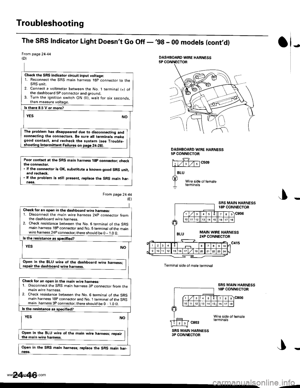
The SRS Indicator Light Doesn't Go Off -,99 - 00 models (cont,d)
Frcm page 24-44{D)
Ch€ck the SRS indicator circuit input voltage:1. Reconnect the SRS main harness 18p connector to theSRS unit.2. Connect a voltmeter between the No. 1 terminal {+) ofthe dashboard 5P connector and ground.3. Turn the ignition switch ON {ll}, wait for six seconds,then measure voltage.
ls there 8.5 V or more?
YESNO
The problem has disapp€ared due to disconnecting andconnecting tho connectors. Be sure all terminals makegood contact, and .echeck the system {seo Troublo_shooting Intermiftent Failures on page 2it-2E).
Poo. contact at the SRS main harn8s 18p connector; checkthe connector.. lf the connoctor is OK, aubstitute a known-good SRS unit,end recheck.. lf the problem is still present, .6place tho SRS m.in har-ne33.
Ftom lage24-44(E)
J)
DASHEOARD WFE HARNESS5P CONNECTOR
c5ott
Wire side of lemaleterminals
J
Torminal side ol male termtnal
ca03
SRS MAIN HARNESS18P CONNECTOR
c806
SRS MAIN HARNESS3P CONNECTOR
DASHBOARD WIRE HARNESS
Check for an open in the dashboa.d wire harnessi1. Disconnect the main wire harness 24p connector fromthe dashboard wire harness.2. Check resistance between the No. 6 terminal of the SRSmain harness 18P connector and No. S te.minal of the mainwire harness 24P connector; there should be 0 - 1.0 0.
ls th€ resistance rs speciliedT
YESNO
Open in the 8LU wi.o ol the dashboard wire hrmess:repair the dashboard wire ha.ness.
Check fo. an open in the m.in wire hamess:1. Disconnect the SRS rnain harness 3p connector from themain wire harness,2. Check resistance between the No. 6 terminal of the SRSrnain harness 18P connector and No. 1 terminal of the SRSmain harness 3P connector;there should be 0 1.0O.
b the rGbtanco as sDecified?
NOYES
Open in the BLU wir6 of th6 main wire hernos3; reori.the main wire hamess,
Open in the SRS main harness; r€place the SRS main ha.-noss.
24-46
--
www.emanualpro.com
Page 1359 of 1395
Troubleshooting
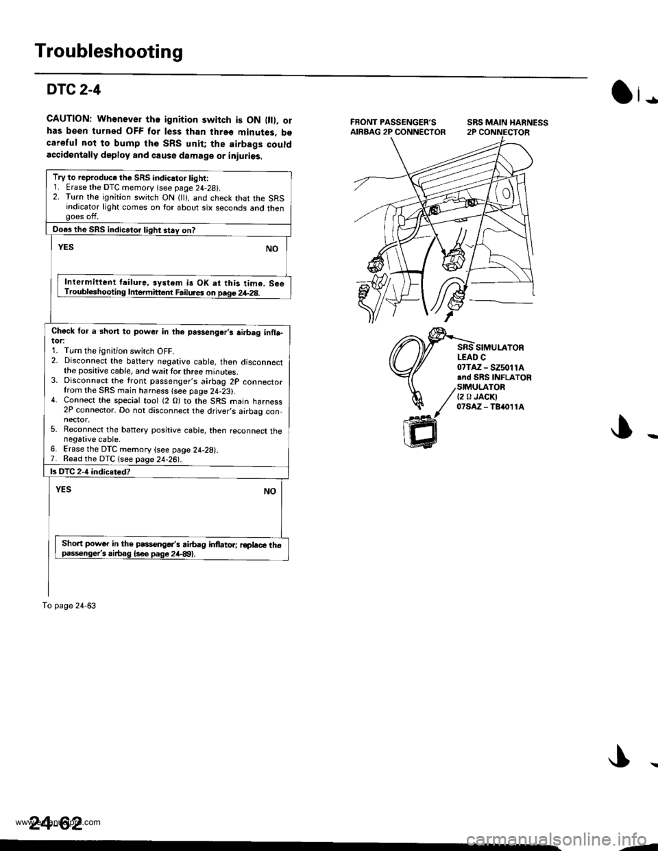
DTC2-4
GAUTION: Wh€never tho ignition switch is ON 0t). orhas been turned OFF for less than threo minutes, bocareful not to bump the SRS unit; the airbags couldaccidentally deploy and cause damaga or iniuriss.
SRS MAIN HARNESS
SIMULAYORLEAD C
Ot-
07TAZ - SZ5011A.nd SRS INFLATOR
/stMU|_ATOR/ t2 tr JAoKI
// olsAz-Tsn11A
ffi
Try to reproduce the SRS indicator light:1. Erase the DTC memory (see page 24-28i.2. Turn the ignition switch ON (lli, and check that the SRSindicator light comes on tor about six seconds and thengoes off.
Do€s the SRS indicator light stay on?
YESNO
Inlermittent tailure, system is OK at this tim€. SceTroubleshooting Intermitt€.f Failures on page 2+28.
Check for a short to power in the passengar,s ai.bag infla-tor:1. Turn the ignition switch OFF.2. Disconnect the baftery negative cable, then disconnectthe positive cable, and wait for three minutes.3. Disconnect the front passenger's airbag 2P connectorIrom the SRS main harness lsee page 24-23).4. Connect the special tool (2 O) to the SRS main harness2P connector. Do not disconnect the driver,s airbag con,nector,5. Reconnect the battery positive cable, then reconnect thenegative cable.6. Erase the DTC memory (see page 24-28).7. Read the DTC (see page 24-26|'.
ls DTC 2-4 indicsted?
YESNO
Sho.t power in the passenger's airbag infator; rsplece thopaisonge/i airbag {s€e pag€ 2il-89).
To page 24-63
24-62
--
www.emanualpro.com
Page 1361 of 1395
Troubleshooting
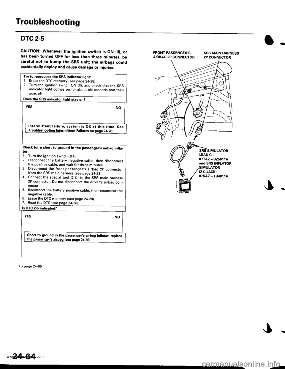
DTC 2-5
CAUTION: Whenever the igniiion switch is ON {ll}, orhas be€n turn€d OFF for less than three minutes, becareful nol to bump the SRS unit; the sirbags couldaccidentally doploy and causo damage or iniuries.
tl
SIMULATORLEAO C07TAZ - SZ5011A.nd SRS INFLATOR
/StMULATOR/ t2 a JACKI
/ 07saz-fB&11^
ffi
Try to rep.oduce the SRS indicstor tight:1. Erase the DTC memory (see page 24-28).2. Turn the ignition switch ON 0l), and check that the SRSindicator light comes on for about six seconds and thengoes off.
ooes th6 SRS indicaror light st.y on?
YESNO
Inte.mitt.nt failure, system is OK at thi3 time. S€eTroubl6hooting Intermittem Failur6 on page 2+28.
Check for a short to gaound in th6 prsenger,i airbag inlla-tor:1. Turn the ignition switch OFF.2. Disconnect the battery nogative cable, then disconnectthe positive cable, and wait for three minutes.3. Disconnect the front passenger,s airbag 2p connectorfrom the SRS main harness {see page 24-23).4. Connect the special tool (2 0) to the SRS main harness2P connector. Do not disconnect the driver,s airbag con,nector.5. Reconnect the battery positive cable, then reconnect thenegative cable.6. Erase the DTC memory (see page 24-28).7. Read the DTC lsee page 2[-261.
ls DTC 2-5 indicated?
YESNO
Short to ground in the pas€ngert airbeg inflator; ,cplacethe passenge/s airbag (s€e page 2+991.
To page 24 65
24-64
--
www.emanualpro.com
Page 1363 of 1395
Troubleshooting
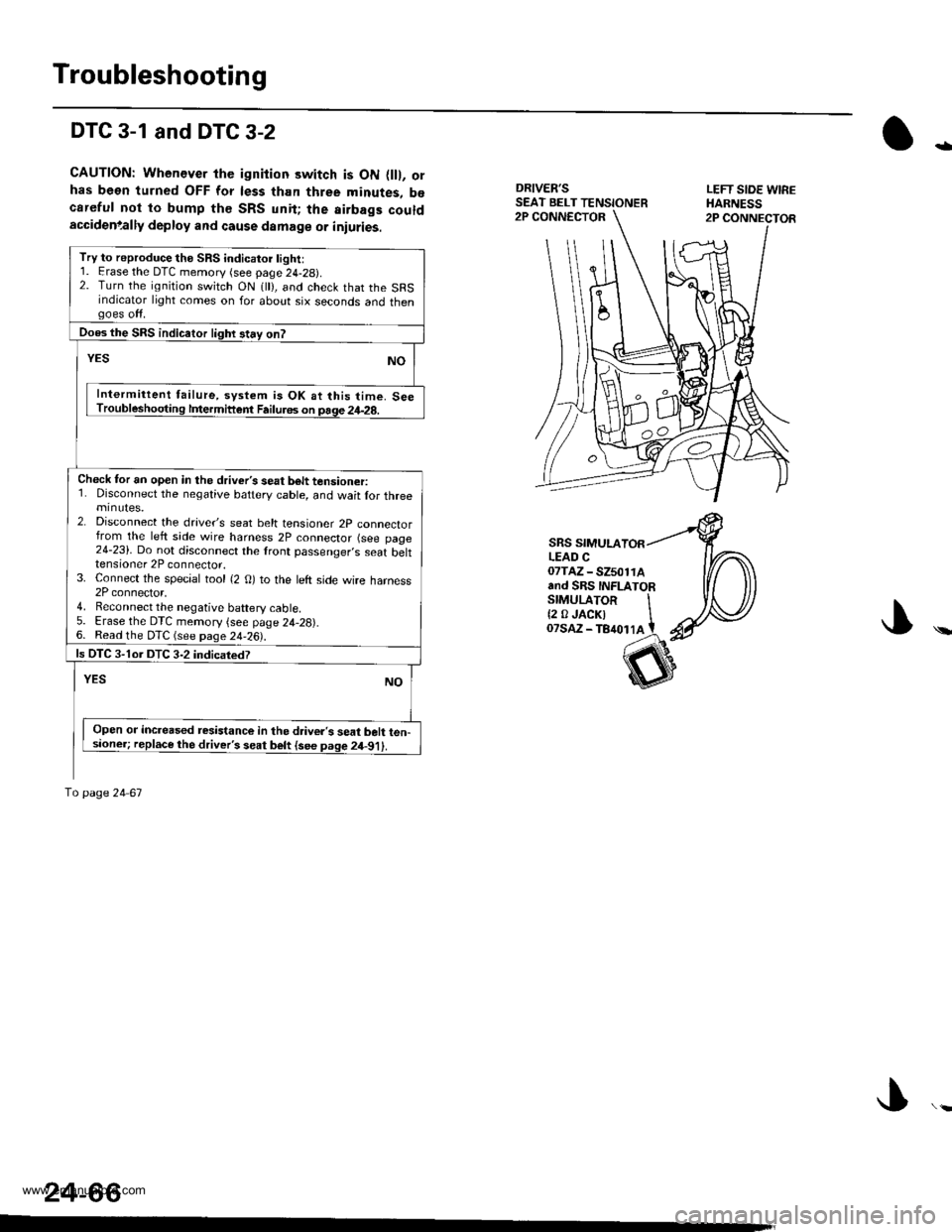
DTC 3-1 and DTC 3-2
CAUTION: Whenever the ignition switch is ON flll, orhas been turned OFF for less than three minutes, b€careful not to bump th€ SRS unit; the airbags couldaccidenlally deploy and cause damage or iniuries.
DRIVER'SSEAT BELT TENSIONERLEFT SIOE WIREHARNESS2P CONNECTOR2P CONNECTOR
-
\
SRS SIMULALEAD C07TAZ - SZ501rAand SRS INFLATORSTMULAToR It2 0JACKI IoTsaz - TB4ot lA t
24-66
Try to reproduce the SRS indicatoi light:1. Erase the DTC memory (see page 24-29).2. Turn the ignition switch ON 1 ), and check that the SRSindicator light comes on for about six seconds and thengoes off.
Does the SRS indicaior lighr stay on?
YESNO
Intermittent failure, system is OK at this time. SeeTroubleshooting lfiermittent Failu.6s on page 24-28.
Check tor an open in the driver's seat b6lt tensioner:1. Disconnect the negative battery cable, and wait lor threeminutes.2. Disconnect the drave/s seat belt tensioner 2p connectorfrom the left side wire harness 2P connector (see page24-23). Do not disconnect the lront passenger,s seat belttensioner 2P connector.3. Connect the special tool {2 O) to the left side wire harness2P connector,4. Reconnect the negative baftery cable5. Erase the DTC memory {see page 24,28).6. Read the DTC (see page 24-26).
ls OTC 3-1or DTC 3-2 indicatedT
YESNO
Open or increased resistance in the d.iver's seat belt ten-sioner; replace the driver's seat belt {see page 2il-91).
To page 24 67
www.emanualpro.com
Page 1365 of 1395
Troubleshooting
DTC 3-3
CAUTION; Whenever the ignition switch is ON llll, or
has b€on turned OFF for l6ss than three minutes, be
carelul not to bump the SRS unit; the airbags could
accidontally deploy and cause damage or iniuries.
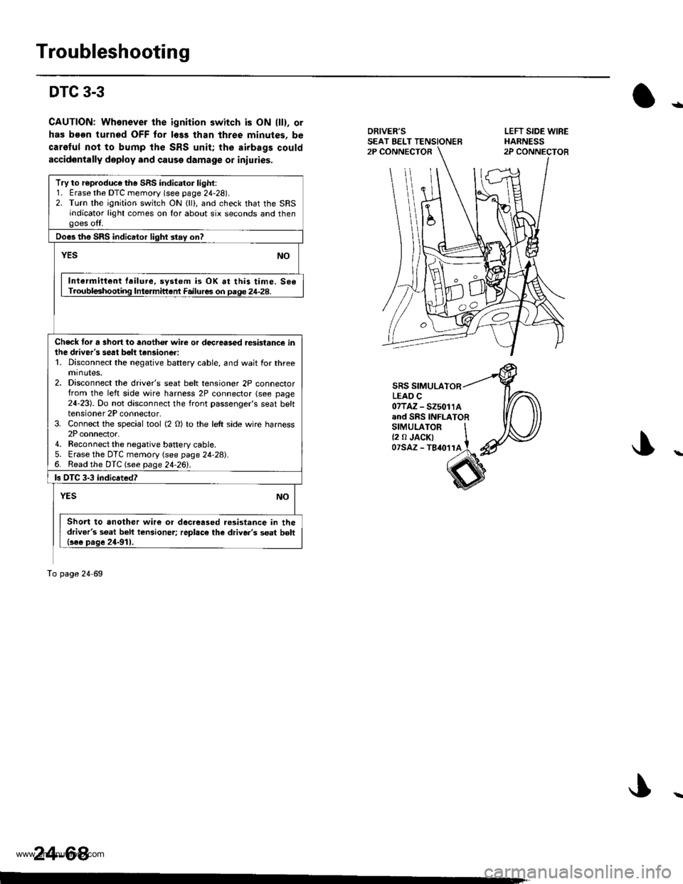
ORIVER'SSEAT EELT TENSIONER2P CONNECTOR
SRS SIMULATORLEAO C07TAZ-525011Aand SRS INFLATORsrMULAroR It2 0 JACK| tozsAz - ls{orra !
s
Try to r€produce the SRS indicator light:1. Erase the DTC memory (see page 24-28).2. Turn the ignition switch ON (lll, and check that the SRSindicator light comes on for about six seconds and thengoes off.
Does the SRS indicator lighl stay on?
YESNO
Intarmittent failure, system is OK at this time. 506Troubl€shooting Intormittant Failures on paqe 24-28.
Check tor a 3hort to anoth€r wire or decreased resistance inihe driver's seat bolt tan3ioneri1. Disconnect the negative battery cable, and wait for threeminutes,2. Disconnect the driver's seat belt tensioner 2P connectorfrom the left side wire harness 2P connector (see page24-23). Do not disconnect the front passenger's seat belttensioner 2P connector,3. Connect the special tool (2 O) to the left side wire harness2P connector.4. Reconnect the negative battery cable5. Erase the DTC memory (see page 24-28).6. Read the DTC (see page 24.26l'.
ls DTC 3-3 indicated?
NOYES
Short to another wire or decreased.esistance in thedriver's s6at beh tcnsioner; replac€ the diive.'s seat bolt{se€ prge 24-911.
To page 24 69
24-64
LEFT SIDE WIREHARNESS2P CONNECTOB
ra
www.emanualpro.com
Page 1375 of 1395
Troubleshooting
DTC 4-4
CAUTION: Whenever the ignition switch is ON (ll), or
has been turned OFF tor less than thlee minutes. be
careful nol to bump the SRS unit; the airbags could
accidontally deploy and cause damage or iniuries.
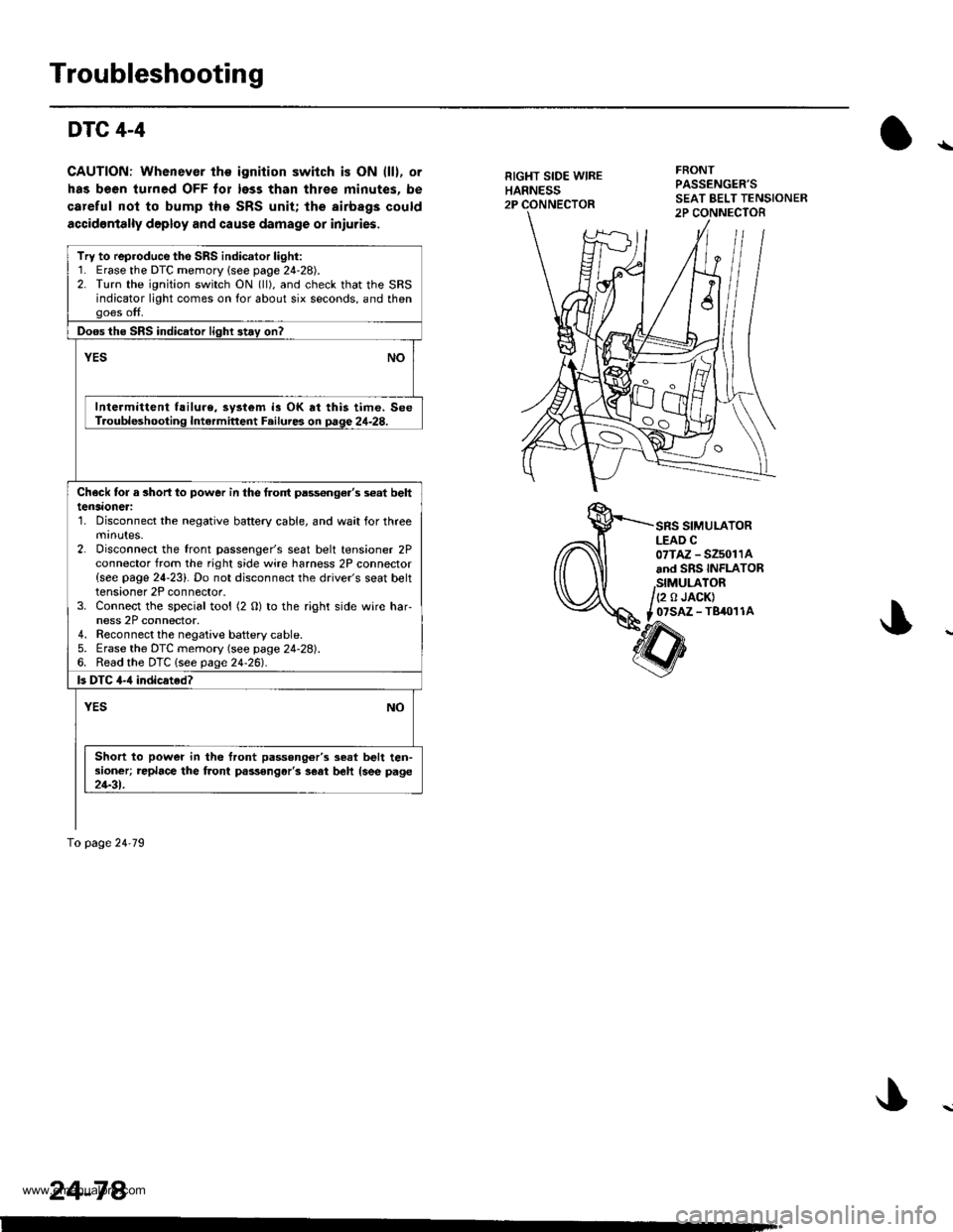
RIGHT SIDE WIREHARNESS2P
FRONTPASSENGER'S
SRS SIMULATORLEAD C07TAZ - SZ5011Aand SRS INFLATOR
,StMULATOR/(2 o JACK)
t _07SAZ - TBiro1 1A
Try to reproduce the SRS indicator light:1. Erase the DTC memory {see page 24-28).2. Turn the ignition switch ON (ll), and check that the SRSindicator light comes on for about six seconds, and thengoes off.
Doos the SRS indicator light 3t.y on?
vEsNO
Intermittent f!ilure, system is OK at this time. SeeT.oubleshooting Intermittent F.ilures on page 24-28.
Check tor a 3horl lo power in the frolt pass€nge.'s s€at belttensaoneri'1. Disconnect the negative battery cable, and wait for threemrnutes.2. Disconnect the front passenger's seat belt tensioner 2Pconnector from the right side wire harness 2P connector{see page 24-23}. Do not disconnect the driver's seat belttensioner 2P connector.3. Connect the special tool (2 O) to the right side wire har-ness 2P connector.4. Reconnect the negaiive baftery cable.5. Erase the DTC memory (see page 24-28).6. Read the DTC lsee page24-261.
ls DTC 4-,1 indicated?
YESNO
Short to power in the front passong6r'3 seat belt ten-sioner; replace the front passongar'3 s€at beh {see page21-31.
To page 24'79
24-78.
www.emanualpro.com
Page 1385 of 1395
Driver's Airbag
Replacement lcont'd)
CAUTION: 8. sure to instattthe SRS wiring so that it isnot plnched or inlerfsring with other parts.
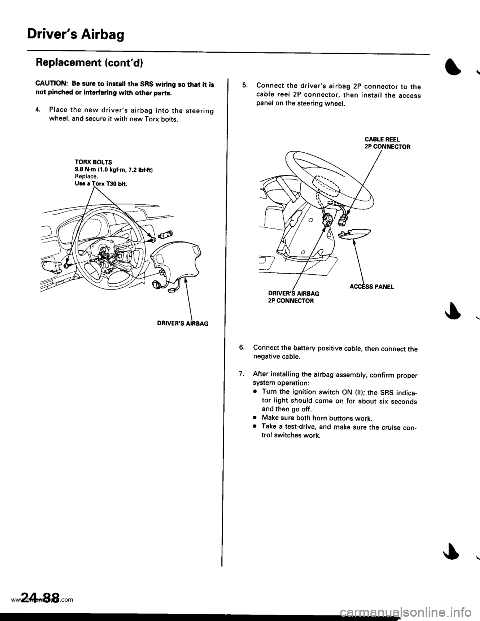
4. Place the new driver's airbag into the steeringwheel, and secure it with new Torx bolts.
TORX EOLTS9.8 N,m 11.0 kgl.m, 7.2 tbf,ftlFeplace.
24-88,
5. Connect the driver's airbsg 2p connector to thecable reel 2P connector, then install the accesspanel on the steering wheel.
Connect the battery positive cable. then connect thenegative cable.
After installing the airbag assembly, confirm proper
system operation:
. Turn the ignition switch ON llt); the SRS indica-tor light should come on for about six secondsand then go off.. Mske sure both horn buttons work.o Take a test-drive, and make sure the cruise con-trol switches work.
7.
2P CONNECTOR
www.emanualpro.com
Page 1393 of 1395
SRS Unit
Replacement (cont'dl
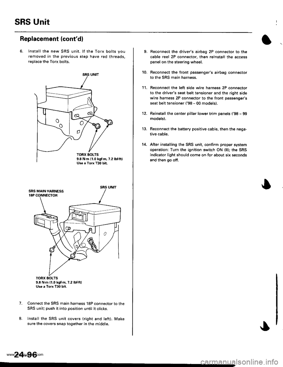
6. lnstall the new SRS unit. lf the Torx bolts you
removed in the previous step have red threads,
replace the Torx bolts.
TORX BOLTS9.8 N.m 11.0 kgf.m,7.2 lbtft)Uso a Torx T30 bit.
Connect the SRS main harness l8P connector to the
SRS uniu push it into position until it clicks.
Install the SRS unit covers (right and left). Make
sure the covers snap together in the middle.
7.
8.
TORX BOLTS9.8 N.m {1.0 kgf.m, ?.2Use . Torx T30 bh,
SRS UNIT
24-96
-
9. Reconnect the driver's aibag 2P connector to the
cable reel 2P connector, then reinstall the access
panel on the steering wheel.
Reconnect the front passenger's airbag connector
to the SRS main harness.
Reconnect the left side wire harness 2P connector
to the driver's seat belt tensioner and the right side
wire harness 2P connector to the front passenger's
seat belt tensioner ('98 - 00 models).
Reinstall the center pillar lower trim panels {'98 - 99
modelsl.
Reconnect the battery positive cable, then the nega-
tive cable.
After installing the SRS unit, confirm proper system
operation: Turn the ignition switch ON (ll); the SRS
indicator light should come on for about six seconds
and then go off,
10.
1't.
12.
13.
14.
www.emanualpro.com