Lock HONDA CR-V 1998 RD1-RD3 / 1.G Workshop Manual
[x] Cancel search | Manufacturer: HONDA, Model Year: 1998, Model line: CR-V, Model: HONDA CR-V 1998 RD1-RD3 / 1.GPages: 1395, PDF Size: 35.62 MB
Page 1288 of 1395
Power Door Locks
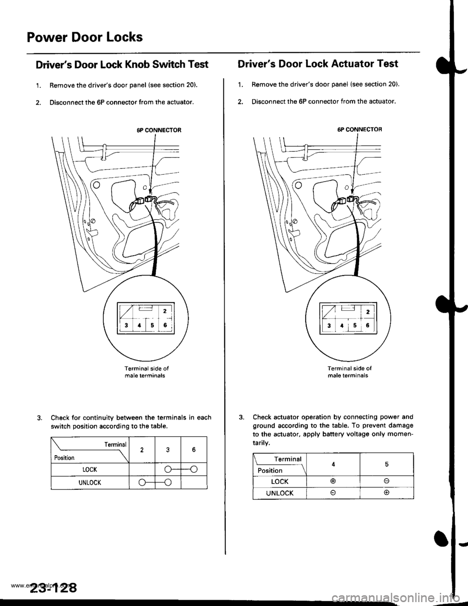
Driver's Door Lock Knob Switch Test
1. Remove the driver's door panel (see section 20).
2. Disconnect the 6P connector from the actuator.
Terminalside otmale terfiinals
Check for continuity between the terminals in each
switch position according to the table.
rsrmrnal
Position \
?6
LOCKo--o
UNLOCKo---o
23-128
.
6P CONNECTOR
Driver's Door Lock Actuator Test
1, Remove the driver's door panel (see section 20).
2. Disconnect the 6P connector from the actuator.
Terminal side ofmale terminals
Check actuator operation by connecting power and
ground according to the table. To prevent damsge
to the actuator. apply battery voltage only momen-
tarilv,
6P CONNECTOR
Terminal
F*'',1."
__l
LOCK@o
UNLOCK@
'-
www.emanualpro.com
Page 1289 of 1395
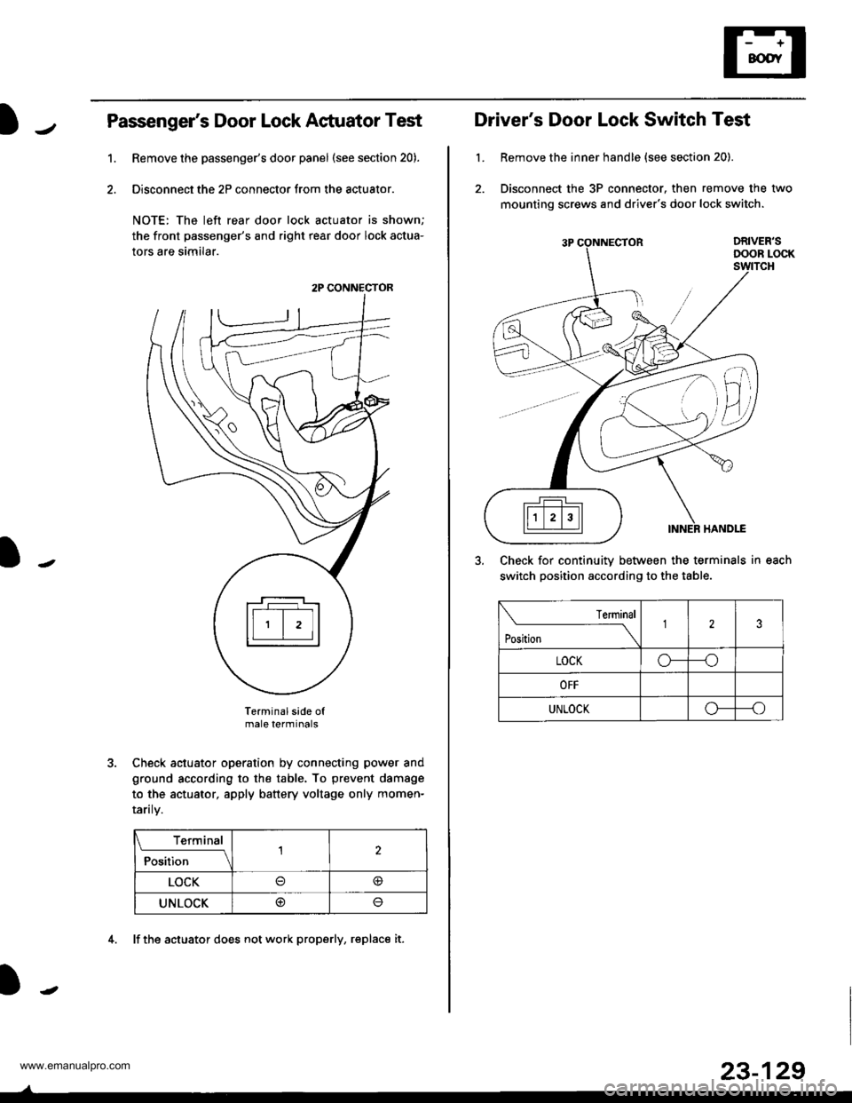
Passenger's Door Lock Actuator Test
Remove the passenger's door panel (see section 20).
Disconnect the 2P connector from the actuator.
NOTE: The left rear door lock actuator is shown;
the front passenger's and right rear door lock actua-
tors are similar.
Terminal side ofmale terminals
Check actuator operation by connecting power and
ground according to the table. To prevent damage
to the actuator, apply battery voltage only momen-
raflry.
Terminal
;;il;--r
,l
LOCK@
UNLOCK@
1.
2P CONNECTOR
4. lf the actuator does not work properly, replace it.
23-129
L
Driver's Door Lock Switch Test
Remove the inner handle {see section 20).
Disconnect the 3P connector. then remove the two
mounting screws and driver's door lock switch.
Check for continuitv between the terminals in each
switch position according to the table.
lermlnal
Position \
123
LOCKo---o
OFF
UNLOCKo--_o
www.emanualpro.com
Page 1290 of 1395
Power Door Locks
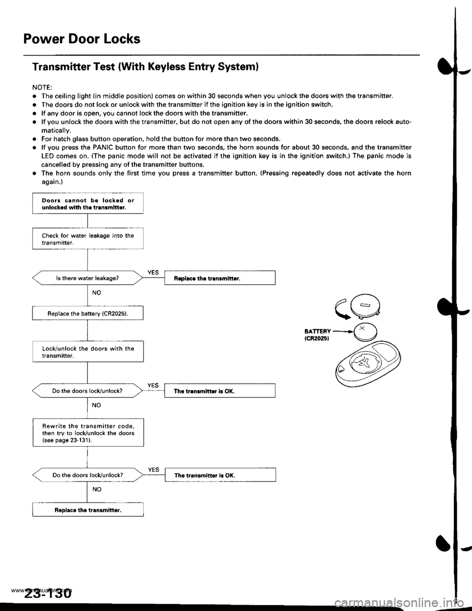
Transmitter Test (With Keyless Entry Systeml
NOTE:
. The ceiling light (in middle position) comes on within 30 seconds when you unlock the doors with the transmitter.
. The doors do not lock or unlock with the transmitter if the ignition key is in the ignition switch.
. lf any door is open, you cannot lockthe doorswith thetransmitter.
o lf you unlock the doors with the transmitter, but do not open any of the doors within 30 seconds, the doors relock auto-
matically.
. For hatch glass button operation, hold the button for more than two seconds.
. lf you press the PANIC button for more than two seconds, the horn sounds for about 30 seconds, and the transmitter
LED comes on. (The panic mode will not be activated if the ignition key is in the ignition switch.) The panic mode is
cancelled by pressing any of the transmitter buftons.
. The horn sounds only the first time you press a transmitter button, (Pressing repeatedly does not activate the horn
again.)
BATTERY{cR20251
23-130
Doors cannot bo locked orunlocked whh lhe transmitter.
Rewrite the transmitter code,then try to locldunlock the doors{see page 23-131}.
www.emanualpro.com
Page 1291 of 1395
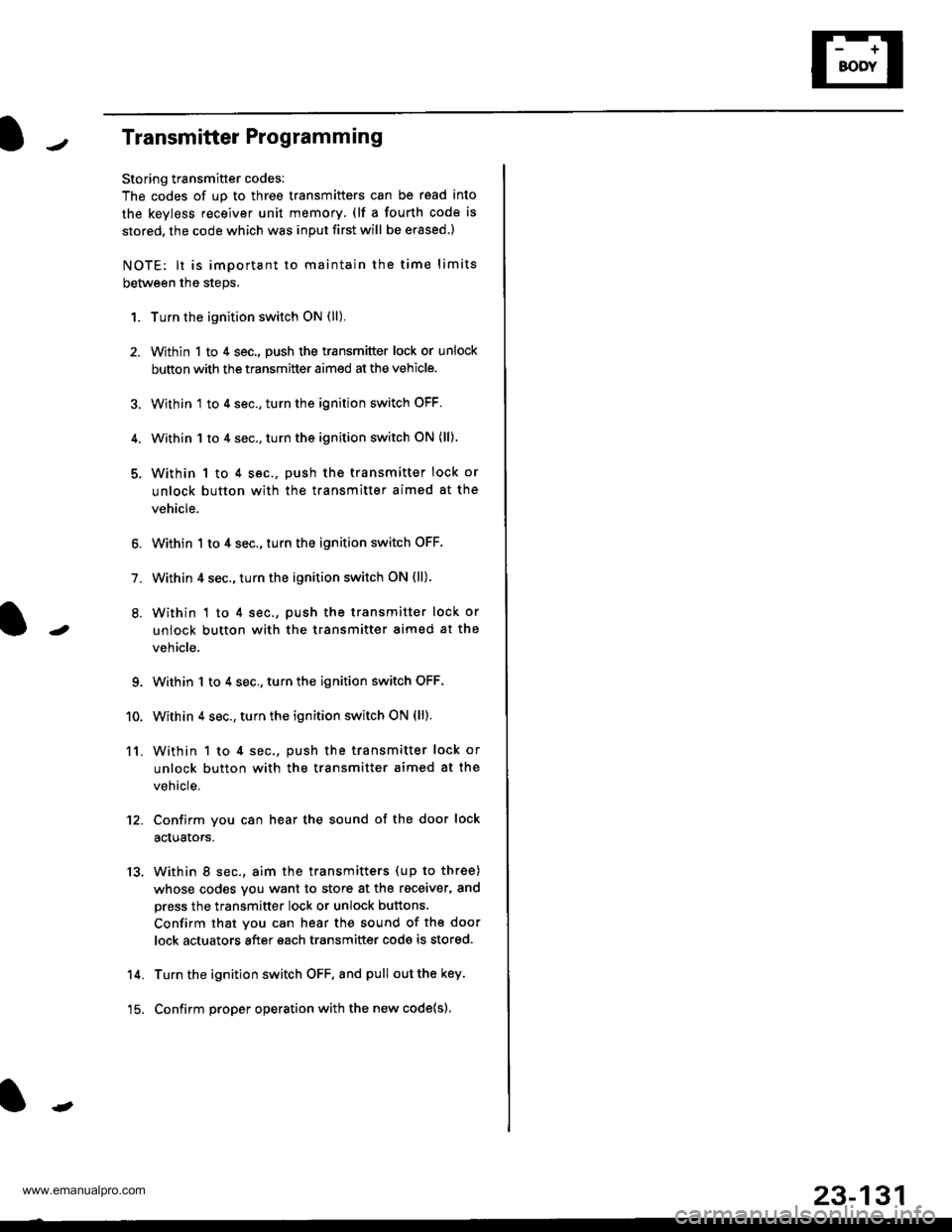
Transmitter Programming
Storing transmitter codes:
The codes of up to three transmitters can be read into
the kevless receiver unit memory (lf a fourth code is
stored. the code which was inDUt first will be erased.)
NOTE: lt is important to maintain the time limits
between the steps.
1.
11.
Turn the ignition switch ON (ll).
Within 1 to 4 sec., push the transmitter lock or unlock
button with the transmitter aimed at the vehicle.
Within 1 to 4 sec., turn the ignition switch OFF.
Within 1 to 4 sec., turn the ignition switch ON (ll).
Within 1 to 4 sec.. push the transmitter lock or
unlock button with the transmitter aimed at the
vehicle.
Within 1 to 4 sec., turn the ignition switch OFF.
Within 4 sec., turn the ignition switch ON {ll).
Within 1 to 4 sec., push the transmitter lock or
unlock button with the transmitter aimed at the
vehicle.
Within 1 to 4 sec., turn the ignition switch OFF,
Within 4 sec., turn the ignition switch ON (ll).
Within 1 to 4 sec., push the transmitter lock of
unlock button with the transmitter aimed at the
vehicle.
Confirm you can hear the sound of the door lock
aduators.
Within 8 sec., aim the transmitters (up to three)
whose codes you want to store at the receiver, and
press the transmitter lock or unlock buttons.
Confirm that you can hear the sound of the door
lock actuators after each transmitter code is stored.
Turn the ignition switch OFF, and pull out the key.
Confirm proper operation with the new code{sl.
-
o.
1.
9.
10.
12.
13.
14.
-
15.
23-131
www.emanualpro.com
Page 1301 of 1395
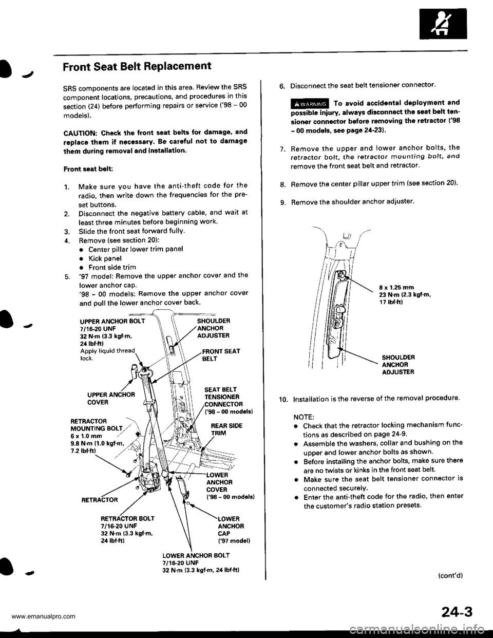
JFront Seat Belt RePlacement
SRS components are located in this area. Review the SRS
component locations, precautions, and procedures in this
section (24) before performing repairs or service ('98 - 00
models).
CAUTION: Check the front seat bslts for damago. and
replaco thom if necessary. Be careful not to damage
them during removal and in3tallation'
Front scat bolt:
1. Make sure you have the anti-theft code for the
radio, then write down the frequencies for the pre-
set buttons.
2. Disconnect the negative battery cable, and wait at
least three minutes before beginning work.
3. Slide the front seat forward fully.
4. Bemove (see section 20):
. Center pillar lower trim Pane
. Kick oanel
. Front side trim
5. '97 model: Remove the upper anchor cover and the
lower anchor caP.'98 - oO models: Remove the upper anchor cover
and pull the lower anchor cover back.
UPPEN ANCHOR BOLT
7/1&20 UNF32 N.m (3.3 kgt'm.24 tbf.ft)
SHOULDERANCHORADJUSTER
Apply liquid threadlock.
9.8 N.m (1.0 kgt.m,?.2 tbtft)
UPPERCOVER
RETRACTORMOUNTING BOLTZ,,Gx1.0mm ./
SEAT BELTTENSIONER
{'98 - 0o modols)
REAR SIDE
ANCHORCOVERl'98 - 00 models)
ANCHORCAP('97 modell
RETRACTOR BOLT7/1&20 UNF32 N.m 13.3 kgt m,24 tbt.ft)
LOWER ANCHOR BOLT?,/1&20 UNF32 N.m {3.3 kgf.m, 2,1 lbf.ftl
o.Disconnect the seat belt tensiongr connector.
@ To avoid accidontal deployment and
possibte inlury, always disconnect the soat bsh ton-
sion€r connoctor bofore rsmoving th6 retractor l'98
- 00 modsls, se€ pa ge 21-231 .
Remove the uDDer and lower anchor boits, the
retractor bolt, the retractor mounting bolt, and
remove the front seat belt and retractor.
Remove the center pillar upper trim (see section 20).
Remove the shoulder anchor adjuster.
7.
9.
8.
I x 1.25 mm23 N.m 12.3 kgt.m,1? tbf.ft)
SHOULDERANCHORADJUSTER
10. lnstallation isthe reverse of the removal procedure.
NOTE:
Check that the retractor locking mechanism func-
tions as described on Page 24-9.
Assemble the washers, collar and bushing on the
uooer and lower anchor bolts as shown.
Eefore installing the anchor bolts, make sure there
are no twists or kinks in the front seat belt.
Make sure the seat belt tensioner connector ls
connected securelv.
Enter the anti-theft code for the radio, then enter
the customer's radio station presets
(cont'd)
24-3
www.emanualpro.com
Page 1303 of 1395
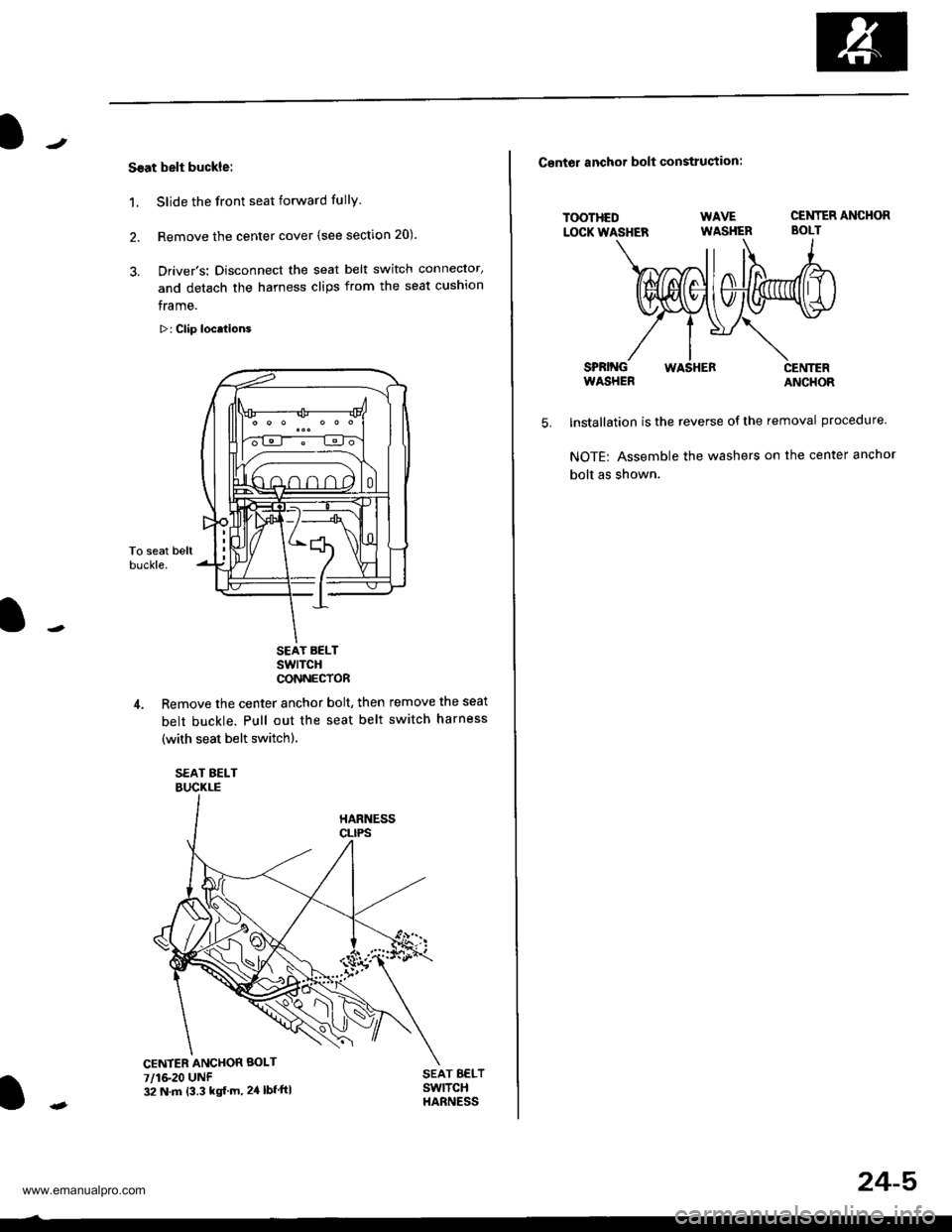
Ssat belt buckle:
1. Slide the front seat forward fully
2. Remove the center cover (see section 20).
3. Driver's: Disconnect the seat belt switch connector,
and detach the harness clips from the seat cushion
frame.
>: Clip locations
To seat beltbuckle.
SEAT BELTswlTcHCONNECTOR
4. Remove the center anchor bolt, then remove the seat
belt buckle. Pull out the seat belt switch harness
(with seat belt switchl.
SEAT BELTBUCKLE
SEAT B€LTSwlTCHHARNESS
CENTER ANCHOR BOLT
7/1&20 UNF32 N.m {3.3 kg{ m, 24 lbf ftl
24-5
Csntor anchor bolt construstion:
TOOTHEDLOCK WASHER
SPRINGWASHERWASHERCENTERANCHOR
WAVE CENTER ANCHOR
WASHER BOLT
5.lnstallation is the reverse of the removal procedure.
NOTE: Assemble the washers on the center anchor
bolt as shown.
www.emanualpro.com
Page 1304 of 1395
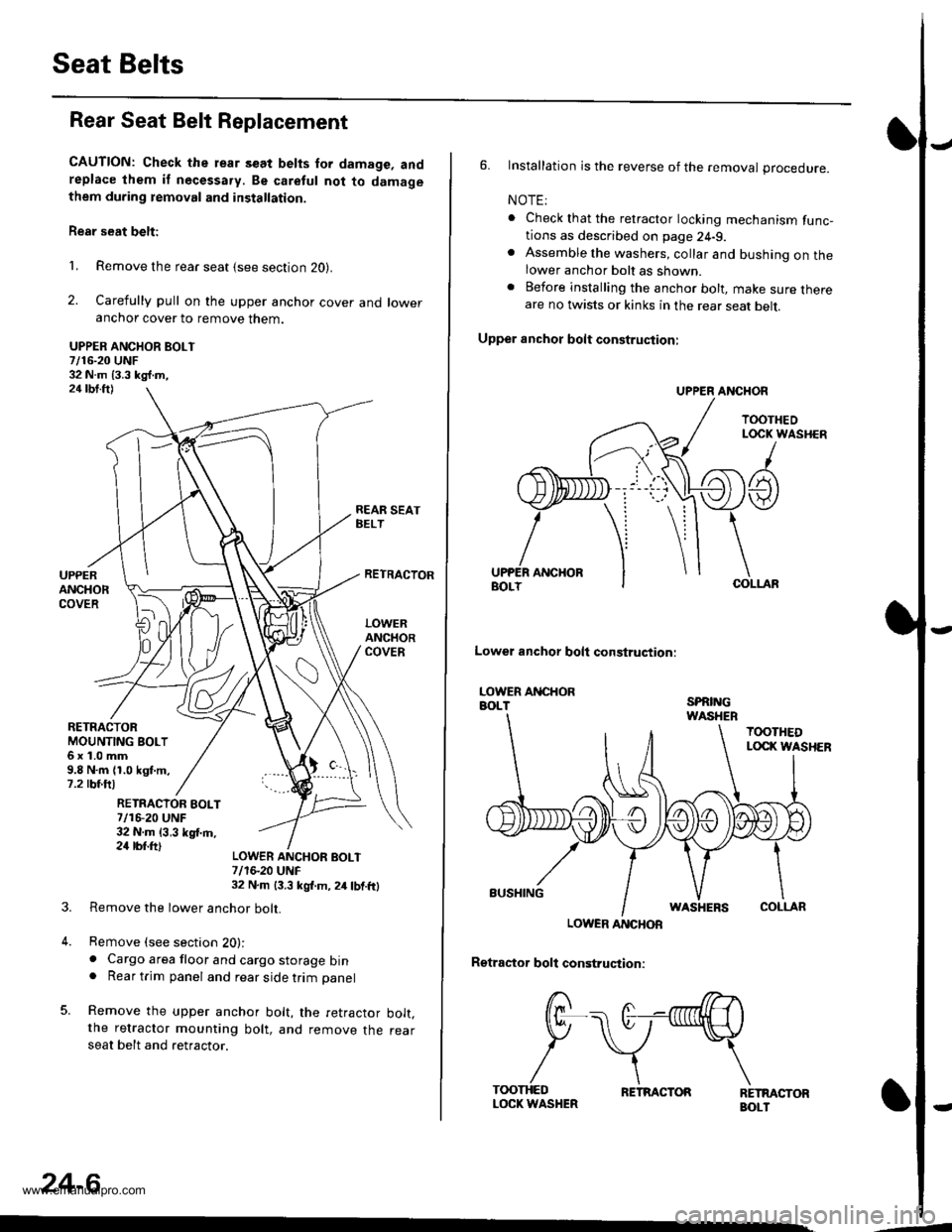
Seat Belts
Rear Seat Belt Replacement
CAUTION: Check the rear s€at belts for damage, andreplace lhem if necessa.y. Be caretul not to damagethem during temoval and installation.
Rear seat belt:
1, Remove the rear seat {see section 20}.
2. Carefully pull on the upper anchor cover and loweranchor cover to remove them.
UPPER ANCHOR BOLT7/16-20 UNF32 N.m 13.3 kg{.m,24 tbt.ft)
REAR SEATBELT
RETRACTOBMOUNTING BOLT6x1.0mm9.8 N.m (1.0 kgt.m.7.2 rbf.ftl
UPPERANCHORCOVER
RETRACTOR
LOWERANCHORCOVER
RETRACIOR EOLT7/16-20 UNF32 N.m {3,3 kgf.m,24 rbr.ft)
3.
4.
LOWER ANCHOF BOLT7/1S20 UNF32 N.m 13.3 kgl.m, 2/r lbf.ftl
Remove the lower anchor bolt.
Remove (see section 20):. Cargo area floor and cargo storage bin. Rear trim panel and rear side trim panel
Remove the upper anchor bolt, the retractor bolt.the retractor mounting bolt, and remove the rearseat belt and retractor.
24-6
,--
6. Installation is the reverse of the removal procedure.
NOTE:
. Check that the retractor locking mechanism func-tions as described on page 24-9.. Assemble the washers, collar and bushing on thelower anchor bolt as shown.. Before installing the anchor bolt, make sure thereare no twists or kinks in the rear seat belt.
Upper anchot bolt construction:
UPPER ANCHOR
TOOTHEOLOCK WASHER
/
A t
ANCHORCOLLAF
Lowel anchor bolt construqtion:
LOWER ANCHORBOLTSPRINGWASHEB
TOOTHEDLOCI( WASHER
BUSHINGWASHERSCOLLAR
LOWER ANCHOR
Rgtractor boll construction:
RETMCTORBOLT
/ r>--->.
f/F\-. (t--nnnllH \
P \v*\
/\\T(X)THEDLOCK WASHERRETRACTOR
www.emanualpro.com
Page 1306 of 1395
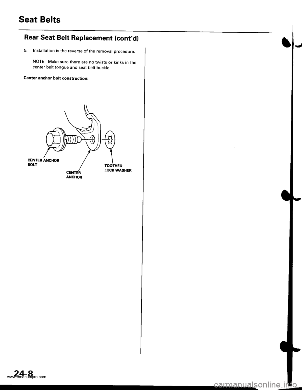
Seat Belts
Rear Seat Belt Replacement (cont'dl
5. Installation is the reverse of the removal Drocedure.
NOTE: Make sure there are no twists or kinks in thecenter belt tongue and seat belt buckle.
Cenler anchor bolt construction:
€
\TOOTHEDLOCK WASHER
ANCHOR
24-8
,-4
www.emanualpro.com
Page 1307 of 1395
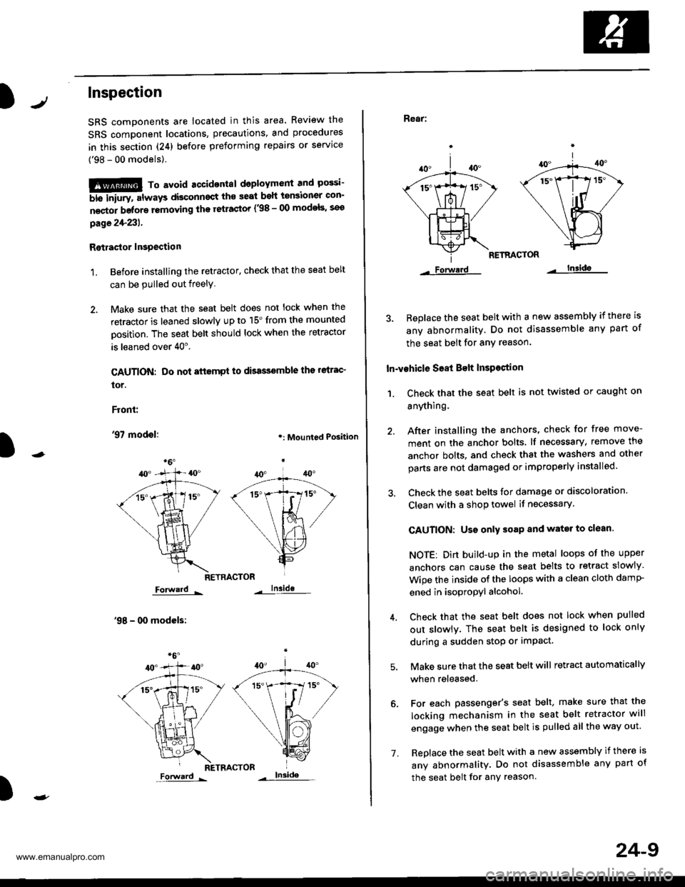
Inspection
SRS components ale located in this area. Review the
SRS component locations, precautions, and procedures
in this section (24) before preforming repairs or service
('98 - 00 models).
!!!@ To avoid accidontal deployment and possi-
6i6-'rnpry. att"ays aisconnsct th€ seat beh tensioner con-
n€ctor belore removing tho retrastor {.98 - 00 modols, seo
page2+231.
Rgtlastor Insgection
1. Before installing the retactor, check that the seat belt
can be pulled out freely
2. Make sure that the seat belt does not lock when the
retractor is leaned slowly up to 15'from the mounted
Dosition. The seat belt should lock when the retractor
is leaned over 40".
CAUTION: Do not attsmpt to dbassemble ths relrac'
tor.
Front:
'97 modol:.: Mounted Position
RETRACTOR
Forward -
'98 - 00 modcls:
lnside
RETRACTOR
)
Forward -
'1.
24-9
Rear:
RETRACTOR
Forwerd lnsida
3. Beplace the seat belt with a new assembly if there is
any abnormality. Do not disassemble any part of
the seat belt for any reason.
In-vehicle S68t Belt InsPestion
1. Ch€ck that the seat belt is not twisted or caught on
anything.
40.
/A
\|_t-.
*1ix
\/
Lls=
Forwerd
After installing the anchors, check for free move-
ment on the anchor bolts lf necessary, remove the
anchor bolts, and check that the washers and other
parts are not damaged or improperly installed.
Check the seat belts for damage or discoloration.
Clean with a shop towel if necessary.
CAUTION: Uso only soap and wator to clean.
NOTE: Dirt build-up in the metal loops of the upper
anchors can cause the seat belts to retract slowly
Wipe the inside of the loops with a clean cloth damP
ened in isopropyl alcohol.
Check that the seat belt does not lock when pulled
out slowlv. The seat belt is designed to lock only
during a sudden stop or impact.
Make sure that the seat belt will retract automatically
when released.
For each passenger's seat belt, make sure that the
locking mechanism in the seat belt retractor will
engage when the seat belt is pulled all the way out.
Replace the seat belt with a new assembly if there is
any abnormality. Do not disassemble any part of
the seat belt for any reason.
www.emanualpro.com
Page 1310 of 1395
)
Supplemental Restraint System (SRS)
Special Tools .."....."" 24-14
Component/Wring Location
lndex - '97 model ..........'.." '.....""" 24-15
Component/Wiring Location
lndex - '98 - 00 models ..............." 24-16
Description .'.........."'.24'17
Circuit Diagram .........24'14
Precautions/Procedures
General Precautions ......".."'........... 24-19
Airbag/Seat Belt Tensioner
Handling and Stolage ....''........... 24-19
SRS Unit Precautions ...............'...... 24-20
lnspeciion After Deployment .......'.24'20
)
with Built-in Short Contact '...'....24-21
Spring-loaded Lock Connectors .."' 24-22
BackProbing SPring-loaded Lock
Conneetors ,.......24-22
Disconnecting the Airbag Connectors and
the Seat Beh Tensioner
Connectors ....'....24-23
Steering-lelated Precautions .......... 24-25
Troubleshooting
Self -diagnostic Procedures ............. 24-26
Reading the DTC .................. .....".."' 24'26
Erasing the DTC Memory ................24-28
Troubleshooting lntermittent
Faifures "'...........24'24
Diagnostic Trouble Gode {DTC}
Chart -'97 model ....""....... "......24-29
Diagnostic Trouble Gode (DTCI
Chart -'98 - 00 models ............. 24-31
SRS Indicator Light Wire
Connections ','," 24'33
Ff owcharts ....-........24'34
Driver's Airbag
Repf acement ..'......21'87
Front Passenger's Airbag
Repfacement .....'.',24'AS
Gable Reel
Replacement .......'.24-91
SRS Unit
Replacement .........24-95
Airbag/Seat Belt Tensioner
Disposaf .................24'97
)-e
www.emanualpro.com