Idle HONDA CR-V 1998 RD1-RD3 / 1.G Owner's Guide
[x] Cancel search | Manufacturer: HONDA, Model Year: 1998, Model line: CR-V, Model: HONDA CR-V 1998 RD1-RD3 / 1.GPages: 1395, PDF Size: 35.62 MB
Page 282 of 1395

PGM-FI System
System Description
INPUTS
CKP/TDC/CYP Sensor
CKF Sensor
MAP Sensor
ECT Sensor
IAT Sensor
TP Sensor
Primary HO2S
Secondary H02S
vss
KS*5
BARO Sensor
ELD*6
Starter Signal
ALT FR Signal
Air Conditioning Signal
Ay'T Gear Position Signal*1
Baftery Voltage (lGN.1)
Brake Switch Signal
PSP Switch Signal
Fuel Tank Pressuae Sensor*4. *5
Countershaft Speed Sensor*1
Mainshaft Speed Sensor*r
OVER-DRIVE Switch Signal*s
ENGINE CONTROL MODULE (ECM)/
POWERTRAIN CONTROL MODULE (PCM) OUTPUTS
|iuel 1"j""- Th,rhg ""d Drrafr";-l
Et*-.nt"tdt"cont.orl
to,r*,c;;trffi;]
l.----.---:. .Lrgnrnon |lmrng Lonrror I
Ecir/PcM B*k',p Fr""il]
m;"t-ll-r*'io*l
Fuel Injectors
PGM-Fl Main Relay (Fuel Pump)
MIL
IAC Valve
Ay'C Compressor Clutch Relay
Radiator Fan Relay
Condenser Fan Relay
ALT
tcM
EVAP Purge Control Solenoid
Valve
Primary HO2S Heater
Secondary H02S HeaterEVAP Bypass Solenoid Valve*a *5
EVAP Control Canister Vent Shut
DLC
Lock-up Control Solenoid Valve*l
Shift Control Solenoid Valve*1
Ay'T Clutch Pressure Control
Solenoid Valve*1
D4 Indicator Light'1 *3, *a
D Indicator Light,l *5
OVER-DRIVE OFF Indicator
Lighl*t *:
*1: A/T {3:'97 model'2: M/f +4:'98 model*5: '99 - 00 models"6: USA
PGM-Fl System
The PGM-Fl system on this model is a sequential multiport fuel injection system.
Fuel iniecior Timing and Duration
The ECM/PCM contains memories for the basic discharge durations at various engine speeds and manifold pressure. The
basic discharge duration, after being read out from the memory, is further modified by signals sent from various sensors
to obtain the final discharge duration.
ldle Air Control
ldle Air Control Valve (lAC Valve)
When the engine is cold, the Ay'C compressor is on, the transmission is in gear, the brake pedal is depressed, the P/S load
is high, or the alternator is charging, the ECM/PCM controls current to the IAC Valve to maintain the correct idle speed.
lgnition Timing Control
o The ECM/PCM contains memories for basic ionition timing at various engine speeds and manifold air flow rates.
lgnition timing is also adjusted for engine coolant temperature.
. A knock control system was adopted which sets the ideal ig nition timing for the octane rating of the gasoline used.*s
Other Control Funstions
1. Starting Control
When the engine is started. the ECM/PCM provides a rich mixture by increasing fuel injector duration.
2. Fuel Pump Control
. When the ignition switch is initially turned on (ll). the ECMiPCM suppli€s ground to the PGM-FI main relay that
supplies current to the fuel pump for two seconds to pressurize the fuel system.
. When the engine is running, the ECM/PCM supplies ground to the PGM-FI main relay that supplies current to the
fuel oumo.
. When the engine is not running and the ignition is on, the ECM/PCM cuts ground to the PGM-FI main relay which
cuts current to the fuel pump.
1 1-80
www.emanualpro.com
Page 283 of 1395

Fuel Cut-off Control
. During deceleration with the throttle valve closed, current to the fuel injectors iscutoffto improvefuel economyat
speeds over 970 rpm ('97 - 98 models), 920 rpm ('99 - 00 modelsl.
. Fuel cut-off action also takes place when engine speed exceeds 6,500 rpm ('97 - 98 models), 6900 rpm ('99 - 00
models), regardless of the position of the throttle valve, to protect the engine from over-rewing.
With Ay'T model. the PCM cuts the fuel at engine speeds over 5,000 rpm when the vehicle is not moving.*'�
4,./C Comoressor Clutch Relav
When the ECM/PCM receives a demand for cooling from the air conditioning system, it delays the compressor from
being energized, and enriches the mixture to assure a smooth transition to the Ay'C mode.
Evaporative Emission (EVAP) Purge Control Solenoid Valve
When the engine coolant temperature is above 154"F (68'C), the ECM/PCM controls the EVAP purge control solenoid
valve which controls vacuum to the EVAP purge control canister,
Alternator Control
The system controls the voltage generated at the alternator in accordance with the electrical load and driving mode.
which reduces the engine load to improve the fuel economy.
PCM Fail-saf e/Back-up Functions
1. Fail-safe Function
When an abnormality occurs in a signal from a sensor, the ECM/PCM ignores that signal and assumes a pre-pre
grammed value for that sensor that allows the engine to continue to run.
2. Back-up Function
When an abnormality occurs in the ECM/PCM itself, the fuel injectors are controlled by a back-up circuit independent
of the system in order to permit minimal driving.
3. Self-diagnosis Function IMalfunction Indicator Lamp (MlL)l
When an abnormality occurs in a signal from a sensor, the ECM/PCM supplies ground for the MIL and stores the DTC
in erasable memory. When the ignition is initially turned on {ll), the ECM/PCM supplies ground for the MIL for two
seconds to check the MIL bulb condition.
4. Two Trio Detection Method
To prevent false indications, the Two Trip Detection Method is used for the HO2S*1, fuel metering-related. idle control
system, ECT sensor and EVAP control system self-diagnostic functions. When an abnormality occurs, the ECM/PCM
stores it in its memory. When the same abnormality recurs after the ignition switch is turned OFF and ON (ll) again,
the ECM/PCM informs the driver by lighting the MlL. However, to ease troubleshooting, this function is cancelled
when you jump the service check connector, The MIL will then blink immediately when an abnormality occurs.
5. Two (or Three) Driving Cycle Detection Method {'97 model)
A "Driving Cycle" consists of starting the engine, beginning closed loop operation, and stopping the engine. lf misfir-
ing that increases emissions or EVAP control system malfunction is detected during two consecutive driving cycles.
or TWC deterioration is detected during three consecutive driving cycles, the ECM/PCM turns the MIL on. However, to
ease troubleshooting, this function is cancelled when you jump the service check connector. The MIL will then blink
immediately when an abnormality occurs.
*1: '97 - 98 models*2: '99 - 00 models
5.
www.emanualpro.com
Page 294 of 1395
![HONDA CR-V 1998 RD1-RD3 / 1.G Owners Guide
PGM-FI System
Manifold Absolute Pressure (MAP) Sensor (contd)
[tn,t nn-] The scan tool indicates Diagnostic Trouble Code (DTC) P0108: A high voltage (low vacuum) problem in the|jg Manifold Absolute HONDA CR-V 1998 RD1-RD3 / 1.G Owners Guide
PGM-FI System
Manifold Absolute Pressure (MAP) Sensor (contd)
[tn,t nn-] The scan tool indicates Diagnostic Trouble Code (DTC) P0108: A high voltage (low vacuum) problem in the|jg Manifold Absolute](/img/13/5778/w960_5778-293.png)
PGM-FI System
Manifold Absolute Pressure (MAP) Sensor (cont'd)
[tn,t nn-] The scan tool indicates Diagnostic Trouble Code (DTC) P0108: A high voltage (low vacuum) problem in the|jg Manifold Absolute Pressure (MAP) sensor.
MAP SENSOR 3P CONNECTOR IC131I
Wire side of female terminals
vcclIYEL/RED}
PCM CONNECTOR D I16PI
JUMPER WIRE
sGlIGRN/WHTI
Wire side of lemale termin6ls
1
(To page 11,93)': '98 - 00 models
1-92
tcRN/wHrll IIRED/GRN|
The MIL has boen reported on.DTC m108 is slored.
Problem veritication:1. Start the engine. Hold theengine at 3,000 rpm with noload (in Park or neutral) untilthe radiator fan comes on, thenlet it idle.2. Check the MAP with the scantool.
Intermittent tailuro, system i3 OKat this time. Check tor ooor con-nections or loose wires at C131IMAP s6nsor) snd the ECM/rcM.
ls 101 kPa {760 mmHg,30 in.Hg),2.9 V or higher indicated?
Check Ior an open in the MAPsensor:1. Turn the ignition switch OFF.2. Disconnect the MAP sensor3P connector.3. lnstall a jumper wire betweenthe MAP sensor 3P connectorterminals No.3 and No.2.4. Turn the ignition switch ON {ll).5. Check the MAP with the scantool.
ls 10'l kPa (760 mmHg,30 in.Hg),2.9 V or higher indicated?
Check for an open in wire (SGlliDel:1. Remove the jumper wire.2. Measure voltage between theMAP sensor 3P connector ter-minals No. 1 and No- 2.
R6p.ir open in the wire betwoenthe ECM/PCM (D12, CTrl and theMAP sensor.
ls there approx. 5 V?
Check for an open in the wire(MAP line):1. Turn the ignition switch OFF.2. lnstall a iumper wire on thePCM connectors between D3and D12.3. Turn the ignition switch ON (ll).4. Check the MAP wirh the scantool.
Ropair opon in the wire betweenthe PCM {D3, .nd the MAP son-3('t.
ls 101 kPa 1760 mmHg, 30 in.Hg),2.9 V or higher indicated?
YES
www.emanualpro.com
Page 296 of 1395
PGM-FI System
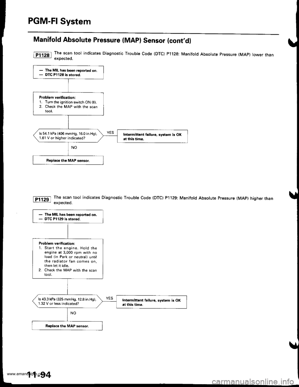
Manifold Absolute Pressure (MAP) Sensor (cont'dl
The scan tool indicates Diagnostic Trouble Code (DTC) P1128: Manifold Absolute pressure (MAp) lower thanexoected.
The scan tool indicates Diagnostic Trouble Code (DTC) P'l129: Manifold Absolute Pressure (MAP) higher thanexpected.
l
- The MIL has be6n r€ported on.- DTC Pl128 is stored.
Problom verification:1. Turn the ignition switch ON 1lli.2. Check the MAP with the scantool,
ls 54.1 kPa (406 mmHg, 16.0 in.Hg),1.61 V or higher indicated?I to.mittent failure, 3ydom i! OKal thbtimc,
- The MIL has boen reportod on.- DTC Pl129 is stored.
Problem veritication:1. Start the engine. Hold theengine at 3,000 rpm with noload lin Park or neutral) untilthe radiator fan comes on,then Iet it idle.2. Check the MAP with the scantool,
ls 43.3 kPa (325 mmHg, 12.8 in.Hg),'1.32 V or less indicated?Intarmittani fuilure, systom i3 OKat this time.
11-94
www.emanualpro.com
Page 301 of 1395
Engine Goolant Temperature (ECTI Sensor
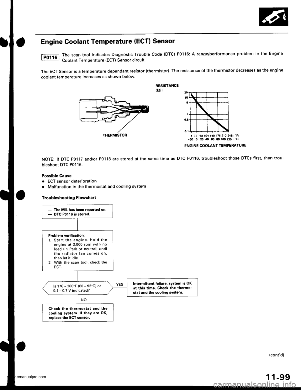
The scan tool indicates Diagnostic Trouble Code (DTC) P0116: A range/performance problem in the Engine
Coolant Temperature (ECT) Sensor circuit.
The ECT Sensor is a temperature dependant resistor (thermistor). The resistance of the thermistor decreases as the engine
coolant temperature increases as shown below
RESISTANCEtk0l
NOTE: lf DTC P0117 and/or P0118 are stored at the same
bleshoot DTC P0116.
Possible Cause
a ECT sensor deterioration
. Malfunction in the thermostat and cooling system
Troubleshooting Flowchart
-4 32 68 r0a r a0176 212 2aE {'r)-2O O 20 ito tO .o ! t2O I c)
ENGINE COOLANT TEMPERATURE
time as DTC P0116, troubleshoot those DTCS first, then trou-
THERMISTON
- The MIL has be€n roported on.- DTC P01'16 is stored.
Probl6m verification:1. Start the engine. Hold theengine at 3,000 rpm with noload (in Park or neutral) untilthe radiator fan comes on,then let it idle.2. With the scan tool, check theECT.
Intermittent failure, sYstem b OKat this tim6. Check lhe thermo-stat and the cooling 5y3tom.
ls 176 - 200'F (80 - 93"C) or0.4-0.TVindicated?
Check the thermostat and the
cooling system. It th€y are OK,reolace the ECT seNor.
(cont'd)
1 1-99
www.emanualpro.com
Page 313 of 1395
{From page 11-110}
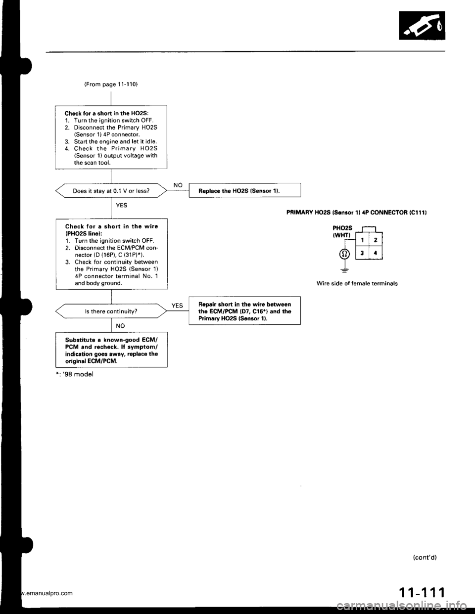
Check tor a shorl in the HO2S:1. Turn the ignition switch OFF.2. Disconnect the Primary HO2S(Sensor'1i 4P connector.3. Start the engine and let it idle.4. Check the Primary HO2S(Sensor 1)output voltage withthe scan tool.
Replace the HO2S {Sensor 1).Does it stay at 0.1 V or less?
Check for a short in the wir€(PH02S linel:1. Turn the ignition switch OFF.2. Disconnect the ECM/PCM con-nector (D (16P), C (31P)*).
3. Check tor continuity betweenthe Primary HO2S {Sensor 1)4P connector terminal No. 1and body ground.
Repair short in tho wire botwesnthe ECM/PCM lD7, C16*) .nd th6Prim.ry HO2S (S€nsor 11.
Substituto a known-good ECM/PCM and recheck. ll 3ympiom/indication goes away. raplace th.origin.l ECM/PCM.
PRIMARY HO2S ls.n.or 'l I 4P CONNECTOR (Cl111
PHO2S ---'trwHTr T-T-l
T-1 1 2l
6tlr rlY r___J_J
L
Wire side of temale terminals
(cont'd)
11-111
www.emanualpro.com
Page 314 of 1395
PGM-FI System
'99 - 00 models:
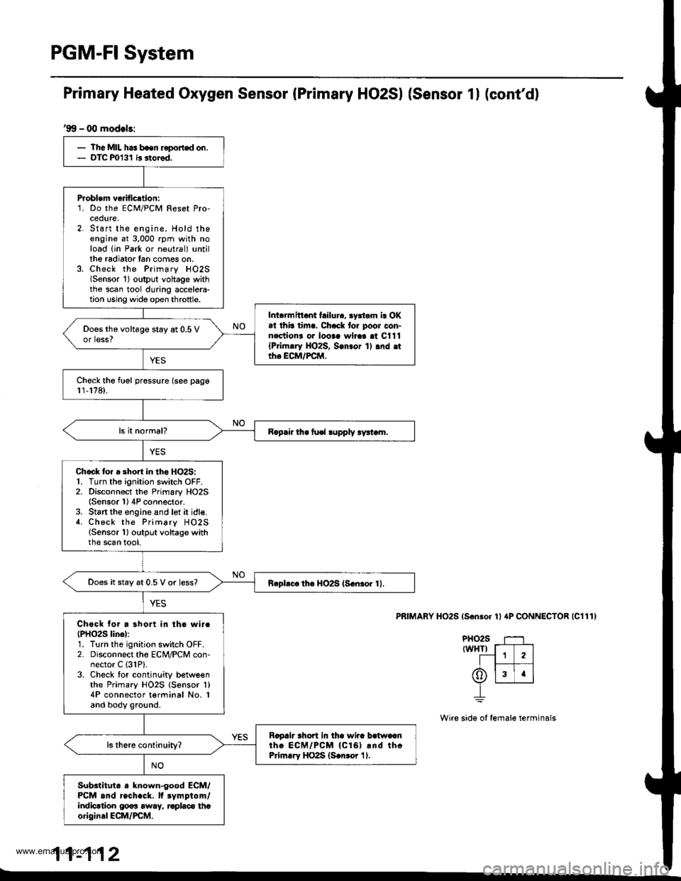
- The MIL has bsen reported on.- DTC P0131 ir storod.
Problem ve fication:1. Do the ECM/PCM Reset Pro-cedure,2. Start the engine. Hold theengine at 3,000 rpm with noload {in Park or neutral) untillhe radiator tan comes on.3. Check the Primary HO2S(Sensor 1) oltput voltage withthe scan tool during accelera-tion using wide op€n throttle.
Inl.rmittant failura, 3yrtam i! OKat thb tim.. Ch.ck tor poor con-nectiona oa looaa wlraa al C111{Pri|n.ry HO2S, Son3or 1l .nd .ttho ECM/FCM,
Does the voltage stay at 0.5 Vor less?
Check tho fuel pressure (see pago1r,178).
R.p.ir th. fu€l lupply ry!t.m.
Chock lor a short in tho HO2S:1. Turn the ignition switch OFF.2. Disconnect the Primary HO2S(Sensor 1) 4P connector.3. St6rt the engine and lot it idle.4. Check the Primary HO2S(Sensor 1) output voltage withthe scan tool,
Does it stay 6t 0.5 V or less?Rephc. th6 HO2S (S.n3or 11.
Chock for a short in tho wirc(PHO2S lino):1. Turn the ignition switch OFF.2. Disconnect the ECM/PCM con-nector C (31P).
3. Check tor continlity betweenthe Primary HO2S {Sensor 'l}
4P connector terminal No. Iand body ground.
Ragah rhort in tha wira balwoanth. ECM/PCM {Cl61 rnd thcPrirn.ry HO2S (S.n3or 11.
Substltut6 a known-good ECM/PCM and recheck. lf rymptom/indicrtion 00os away, raplaco thcoriginal ECM/PCM.
Primary Heated Oxygen Sensor (Primary HO2SI (Sensor 1l (cont'd)
PRIMARY HO2S (Son.or 1l aP CONNECTOR |C111)
PHO2S T--1rwHTr f-T---]
--1 1 2lI t--- 1t6)lslrlv L__r__J
_L
Wire side ol female terminals
11-112
www.emanualpro.com
Page 331 of 1395
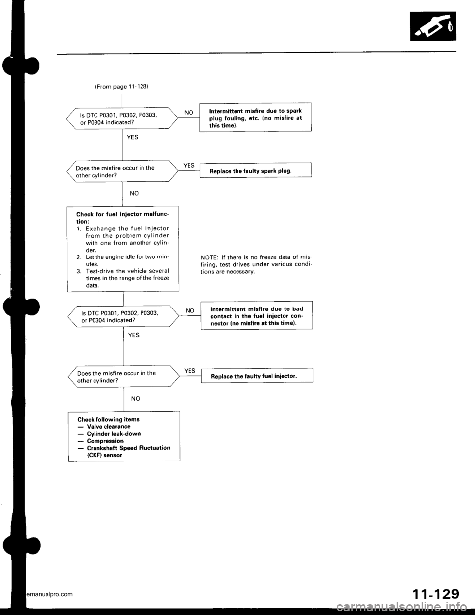
(From page 11-128)
lntormittent misfire due lo sparkplug fouling, etc. (no mislire at
this tim€).
ls DTC P0301, P0302, P0303,or P0304 indicated?
ooes the misfire occur in theother cylinder?Replace the faulty spark Plug.
Check lor fuel iniector maltunc-
t|on:1. Exchange the fuel injectorfrom the problem cylinderwith one from another cylin-der.2. Let the engine idle for two min
utes.3. Test'drive the vehicle severaltimes in the range of the freezedata,
lntermittent misfiro due lo bad
contrct in the fuel iniector con-nector {no misfire at this time).
ls DTC P0301, P0302, P0303,or P0304 indicated?
Does the misfire occur in theother cylinder?Replace lhe faulty luel inlector.
Check following items- Valvo clearance- Cvlinder l€ak-down- Compression- Crsnkshaft Speed FluctuationICKF) sensol
NOTE: lf there is no freeze data of misfiring, test drives under various condi_
tions are necessary.
11-129
www.emanualpro.com
Page 332 of 1395
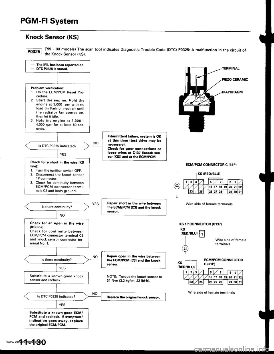
PGM-FI System
Knock Sensor {KSl
('99 - 00 models) The scan tool indicates Diagnostic Troublo Code (DTC) P0325: A malfunction in the circuit ofthe Knock Sensor (KS).
ECM/PCM CONNECTOR C 131P}
Wire side of female terminals
KS 1P CONNECTOR IC13?'
KSIRED/BLU)
KS(BED/BLU)
Wire side ol femaletermtnals
ECM/PCM CONNECTORc (31P)
- The MIL has been rooorted on.- DTC m325 is storod.
Problem verification:1. Do the ECM/PCir, Reset Procedure,2. Start the engine. Hold theengine at 3,000 rpm with noload (in Park or neutral) untilthe radiator tan comes on,then let it idle.3. Hold the engine at 3,000 -
4,000 rpm for at least 60 sec-onds,
Intermittent lailu.e, 3ystom is OKat thi3 tim. (te3t drive m.y benacalLrYr.Chock to. poor connsctions olloora wiros rt C137 lknock aon-.o. (KS)) and ar the ECM/FCM.
Ch€ck tor a short in the wir6 {KSlinel:1. Turn the ignition switch OFF.2, Disconnect the knock sensorlP connector.3. Check lor continuity betweenECM/PCM connector terminals C3 and body ground.
Replil rhort in the n irg b6{wocntho ECM/PCM lc:ll and the knocks€ngr1.
Check fo..n open in the wire{KS line):Check for continuity betweenECM/PCM connector terminal C3and knock sensor connector ter,minal No. 1.
B.pair opon in the wirc lrotweenlho ECM/PCM lctl and thc knockacnsor.
ls there cont;nuity?
Substitute a known-good knocksensor and recheck.
ls DTC P0325 indicated?Bcpl.ce the original knock 3€nsor,
Substituto a known-good ECM/PCM and .echeck. lf 3ymptom/indication goes away, replacethe original ECM/PCM.
NOTE: Torque the knock s6nsor to31 N.m (3.2 kgl.m, 23 lbf.ft).
1 1-130
Wire side ot female terminals
www.emanualpro.com
Page 339 of 1395
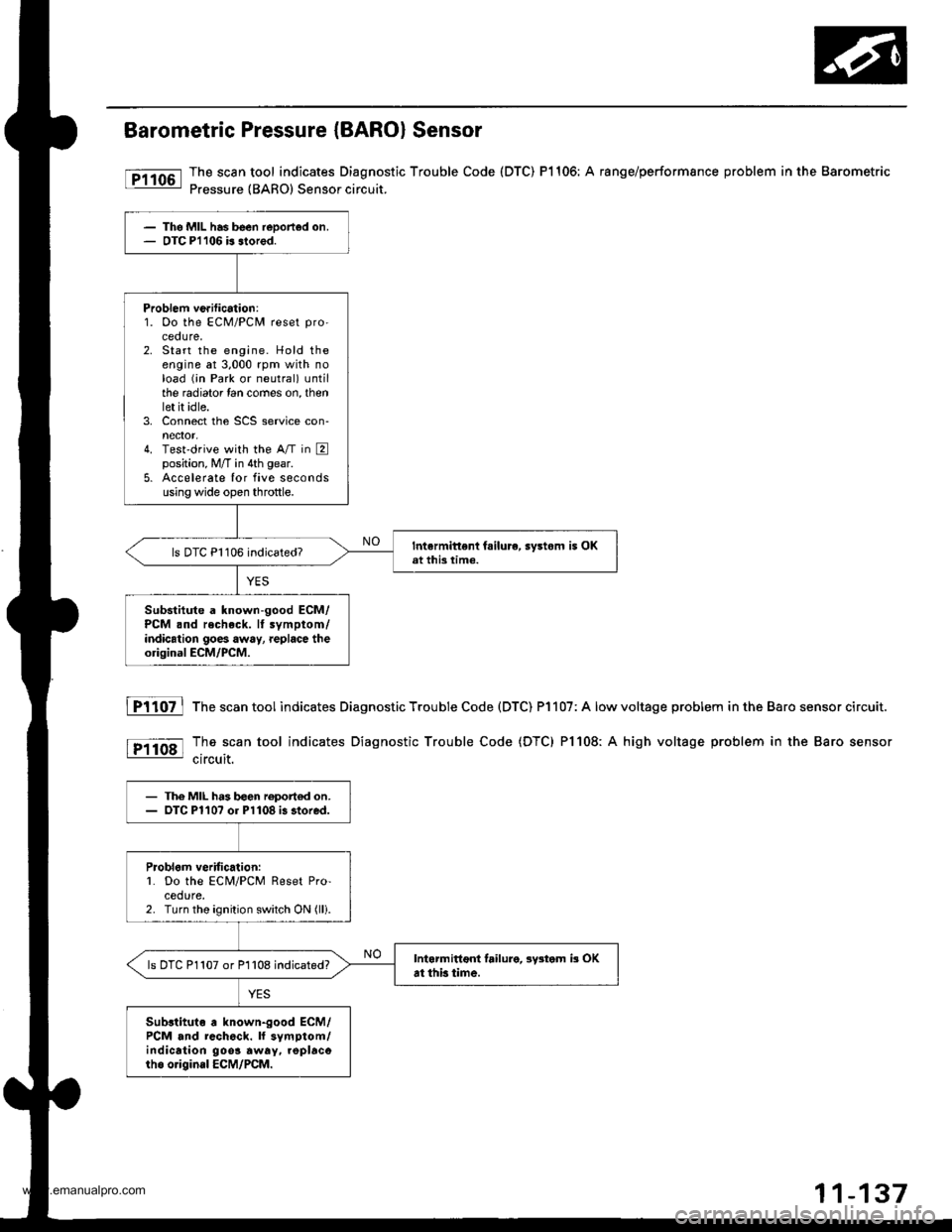
Barometric Pressure (BARO) Sensor
The scan tool indicates Diagnostic Trouble Code (DTC) P1106: A range/performsnce problem in the Barometric
Pressure {BARO) Sensor circuit.
The MIL has been reDorted on.OTC Pl106 b slored.
Problem ve.ification:1. Oo the ECM/PCM reset pro'
ceoure.2. Start the engine. Hold theengine at 3,000 rpm with noload (;n Park or neutral) untilthe radiator lan comes on, thenlet it idle.3. Connect the SCS service con-nector,4. Test'drive with the A/T in Eposition, M/T in 4th gear.
5. Accelerate Ior five secondsusing wide open throttle.
Intermittent fsilure, sy3tom i5 OKat this time.ls DTC P1106 indicated?
Substitute a known-good ECM/PCM .nd recheck. It symptom/indication goes away, replace theorigioal ECM/PCM.
fTiloz l
tP11o8l
The scan tool indicates Diagnostic Trouble Code (DTC) P1107: A low
The scan tool indicates Diagnostic Trouble Code (DTC) Pl108: A
circuit.
voltage problem in the Baro sensor circuit.
high voltage problem in the Baro sensor
- The MIL h.3 b€en roport€d on.- OTC Pl10? or Pl108 i3 stored.
Problom veritic.lion:L Do the ECM/PCM Reset Pro-cedure.2. Turn the ignition switch ON (lli.
Intarmittoni failure, lystom b OKat thb time.ls DTC P1107 or P1108 indicated?
Sub3tituto a known-good ECM/PCM and rcch6ck. ll symptom/indication 9oo3 away. .oplacorho o.igin.l ECM/PCM.
www.emanualpro.com