Jack HONDA CR-V 1998 RD1-RD3 / 1.G Owner's Guide
[x] Cancel search | Manufacturer: HONDA, Model Year: 1998, Model line: CR-V, Model: HONDA CR-V 1998 RD1-RD3 / 1.GPages: 1395, PDF Size: 35.62 MB
Page 1366 of 1395
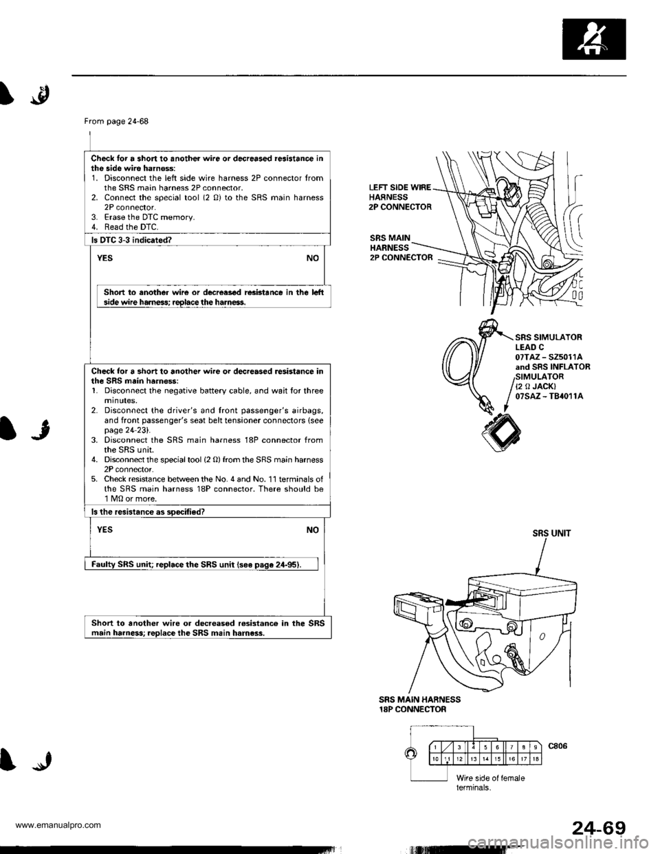
From page 24-68
Check lor a short to another wire or decreased reaistance inthe side wire harnoss:1. Disconnect the left side wire harness 2P connector tromthe SRS main harness 2P connector.2. Connect the special tool (2 0) to the SRS main harness2P connector.3. Erase the DTC memory.4. Read the DTC.
ls OTC 3-3 indicated?
YESNO
Short to another wire or decrcased resbtance in the le-hside wire harness; reglace the harneas.
Check lor a 3hort to another wire or dec.eased resistance inthe SRS main ha.ne$:1. Disconnect the negative battery cable, and wait for threeminutes,2. Disconnect the driver's and front passenger's airbags,and front passenger's seat belt tensioner connectors (seepage 24 23l'.3. Disconnect the SRS main harness 18P connector fromthe SRS unit.4. Disconnect the special tool (2 O) from the SRS main harness2P connector.5. Check resistance between the No. 4 and No. 11 terminals ofthe SRS main harness 18P connector. There should be1 M0 or more.
ls the resistanc€ as soocified?
NOYES
Faulty SRS unit; replace the SRS unit lso€ paqe 24-95).
Short to another wire or decr€asod rosistanco in the SBSmain harness; replace the SRS main harness.
\.p
LEFT SIDE WIREHARNESS2P CONNECTOR
SRS MAINHANNESS
C0a
2P CONNECTOR
SRS SIMULATORLEAD C07TAZ - SZ5011Aand SRS INFLAToRSIMULATOR{2 0 JACK}07sAz - TB4011A
IJ
SRS MAIN HARNESS18P CONNECTOR
SRS UNIT
lerminals.
IJ
t,rutEr-
24-69
www.emanualpro.com
Page 1367 of 1395
Troubleshooting
DTC 3-4
CAUTION: Whenever the ignition switch is ON (lll, ol
has been turned OFF for l6ss than thr6e minutes, b€
careful not to bump the SRS unit; lho airbags could
accidentally deploy and caus€ damage or iniuries.
{
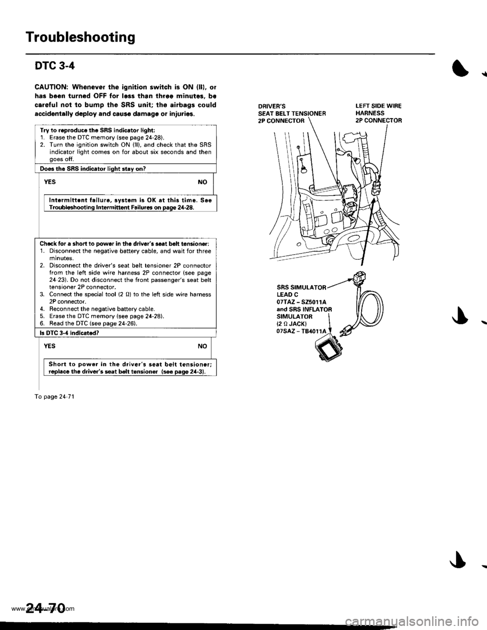
DRIVER'SSEAT BELT TENSIONER2P CONNECTOR
LEFT SIDE WIREHARNESS2P CONNECIOR
SRS SIMULATORLEAD C07TAZ - SZ5011Aand SRS INFLATORSIMULATOR I{2 o JACK} Iozsaz - tamrrl i
Try lo reproduco th6 SRS indicator light:1. Erasethe DTC memory (see page 24-28).2. Turn the ignition switch ON (ll), and check that the SRSindicator light comes on for about six seconds and thenooes off,
Doe3 the SRS indicator liqht stav on?
NOYES
Intcrmitt.nt f.ilur., iystem is OK at this time. SoeTroubla3hooting Intermittent Failurca on Dage 24-28.
Checklor a shortlo Dowar in the driver'3 3€at beh tonsioncr:1. Disconnoct the negative battery cable, and wait for threeminutes.2. Disconnect the driver's seat belt tensioner 2P connectorfrom the left side wire harness 2P connector (see page24 23). Do not disconnect the front passenger's seat belttensioner 2P connector,3. Connect the special tool {2 0) to the left side wire harness2P connector.4. Reconnect the negative battery cable.5. Erase the DTC memory {see page 24-28).6. Read the DTC (see page 24-26).
ls DTC 3-4 indicsted?
NOYES
Short to powar in the d.iver's seat belt tensioner;replace the d.iver's seat belt tensione. {3ee pago 2il-31.
To page 24'71
24-70
www.emanualpro.com
Page 1368 of 1395
)
From page 24-70
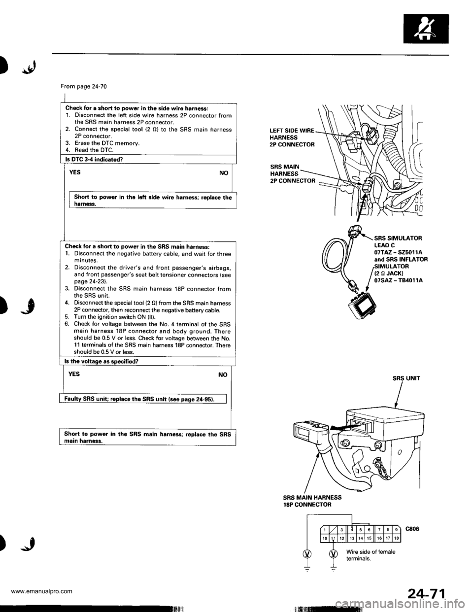
Chock tor a short lo power in the sid€ wi.e harness:1. Disconnect the left side wire harness 2P connector fromthe SRS main harness 2P connector.2. Connect the sDecial tool {2 O) to the SRS maan harness2P connector,3. Eraso the DTC memory.4. Read the DTC.
b DTC 3-4 indiclted?
NOYES
Short to power in the left side wire ha.n6ss; replece thenarness.
Check for a short to power in the SRS mein harness:1. Disconnect the negative battery cable, and wait for threemrnutes.2. Disconnect the driver's and lront passenger's airbags,and front passenger's seat belt tensioner connectors (seepage 24-231.3. Disconnect the SRS main harness 18P connector tromthe SRS unit.4. Disconnectthe specialtool(2 0)from the SRS main harness2P connector, then reconnectthe negative battery cable.5. Turn the ignition switch ON (lll.6. Check lor voltage between the No. 4 terminal ol the SFSmain harness '18P connector and body ground. Thereshould be 0.5 V or less. Check for voltage between the No.11 terminals ol the SRS main harness 18P connector. Thereshould be 0.5 V or less.
ls tho voltage as specffied?
YESNO
Faulty SRS unit; replace tho SRS unit lsee paqe 24-95).
Short to power in the SRS m.in harness;.eplace the SRSmain hame3a.
LEFT SIDE WIREHARNESS2P CONNECTOR
SRS MAINHARNESS
h
(
C
00
2P CONNECTOR
SRS SIMULATORLEAO C07TAZ - SZ5011Aand SRS INFLATOR
(2 0 JACKI07SAZ - TB/t011A
)
SRS MAIN HARNESS18P CONNECTOR
)
24-71
www.emanualpro.com
Page 1369 of 1395
Troubleshooting
DTC 3-5
CAUTION: Whonover tho ignition switch is ON (ll), or
has been turned OFF for less than thres minutes, b€
careful not to bump the SRS unit; the airbags could
accidontally deploy and cause damsgo or iniurirs.
*r
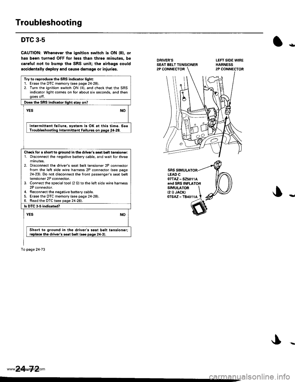
DRIVER'SSEAT BELT TENSIONER
SRS SIMULATORLEAD C07TAZ-S25011Aand SRS INFLATORSIMULATOR \(2 0 JACK' Iozsnz -teronl t
Try to reproduco the SRS indioto. light:1. Erase the DTC memory (s66 pag6 24-28).2. Turn the ignition switch ON (ll), and check that the SRSindicator light comos on Ior about six seconds, and thengoes off.
Do€. the SRS indicsto. light 3tav on?
YESNO
lnto.mitlont hilure, ryltom is OK at thia timc. SesT.oubleshootinq Intermittont Failuros on page 2+28.
Ch€ck for a short to ground in the djivoi's soat b6h tonsioner:1. Disconnect the negative battery cable, and wait tor threemtnutes.2. Disconnoct the driver's seat belt tensioner 2P connectorIrom the l€ft side wire harness 2P connector (see page24-23). Do not disconnect the front passenger's seat belttensioner 2P connector.3. Connect the special tool (2 0) to the left side wire harness2P connector,4. Rgconnect the negative battery cable.5. Erase the DTC memory (see page 24-28).6. Read the DTC (see page 21-26).
ls DTC 3-5 indicated?
YESNO
Short to ground in the driver's soai belt tensioner;repllce the driver'3 seat belt ls€e Daq6 24-31.
To page 2a-73
24-72
www.emanualpro.com
Page 1370 of 1395
)
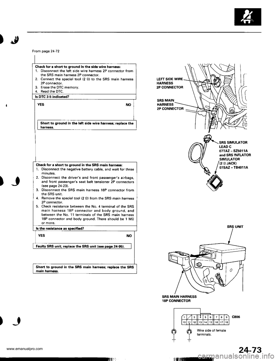
LEFT SIDE wlREHARNESS2P CONNECTOR
SRS MAINHARNESS
(
C
00
2P CONNECTOR
SRS SIMULATORLEAD C07TAZ - SZ5011Aand SRS INFLATORSIMULATOR
/ (2 o JACK)
/ 07sAz - TB4o11A
I
)
SRS MAIN HABNESS18P CONNECTOR
)
Frcm page24-12
Check lor . short to ground in lhe lido wire hrrnassi1. Disconnect the l€lt side wiro hamess 2P connector fromthe SRS main harness 2P connector.2. Connect the special tool (2 0) to the SRS main harness2P connoctor.3. Erase the DTC memory.4. Read the DTC.
Short to ground in the lolt side wi.e harno3s; .eplsce thehamer3.
Check for a short to ground in tho SRS main harna+t:1. Disconnect tho negative battery cable, and wait for threemtnutes.2. Disconnect the drive/s and front passenger's airbags,and front passenger's seat bolt tensioner 2P connectors(see page 24-231.3. Disconnect the SRS main harness l8P connector fromthe SRS unit.4. Remove the spacialtool {2 0) from the SRS main hamess2P connector,5. Check resistance between the No. 4 terminal of the SRSmain harness 18P connector and body ground, andbetween the No. ll terminals ofthe SRS main harness18P connector and body ground. There should be 1 M0or more.
Short to ground in the SRS m.in hrrnar3; roplaco tho SRSmein hamoSs.
24-73
www.emanualpro.com
Page 1372 of 1395
)
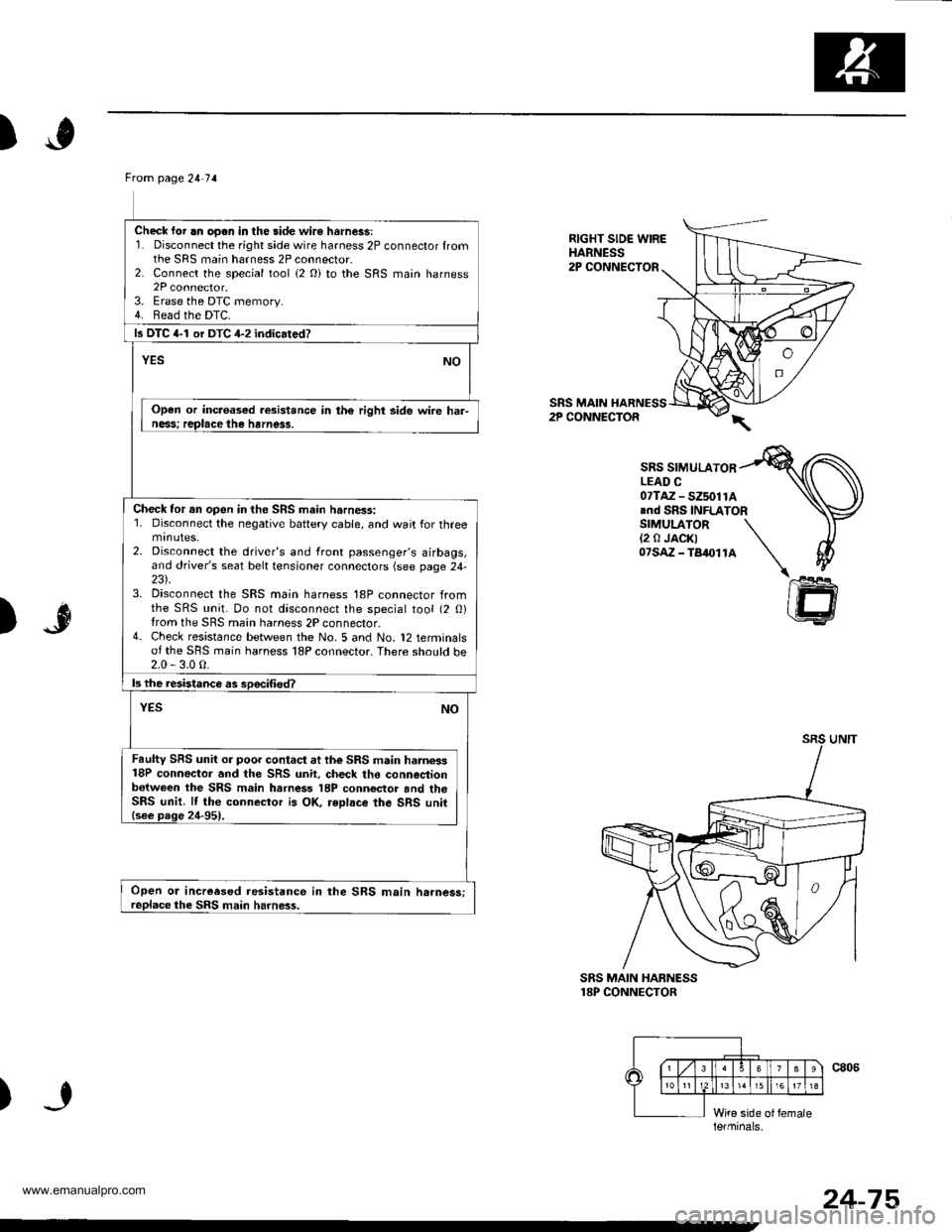
Ftom page 2!-7 a
Check lor .n oo.n in the side wire hsrness:1. Disconnect the right side wire harness 2P connector fromthe SRS main harness 2P connector.2. Connect the special tool (2 Oi to the SRS main harness2P connector.3. Erase the DTC memory.4. Bead the DTC.
ls DTC 4-1 or DTC 4-2 indicated?
NOYES
Open or inc.oased resistance in th€ right side wire har-ness; replace the harness.
Check tor an open in the SRS main harness:1. Disconnect the negative battery cable, and wait for threemtnutes.2. Disconnect the driver's and front passenger's airbags,and driver's seat belt tensioner connectors (see page 24-23\.3. Disconnect the SRS main harness 18P connector fromthe SRS unit. Do not disconnect the special tool (2 0)from the SRS main harness 2P connector.4- Check resistance between the No. 5 and No. 12 terminalsof the SRS main harness 18P connector. There sho!ld be2.0 - 3.0 0.
ls the resistanca as soecified?
NOYES
Faulty SRS unit or poor contact at the SRS main harne3s18P conneclor and the SRS unit, check the connestionb€tween the SRS main harness 18P conn€ctor and th6SRS unit. lf the connector is OK, reDlace the SRS unit{see page 24-951.
Open or increesed resistanco in the SRS main h.rnes3;replace the SRS main harness.
RIGHT SIDE WIREHARNESS2P CONNECTOR
SRS MAIN HARNESS2P CONNECTOR
SRS SIMULATORLEAD C07TAZ - SZ5011A.nd SRS INFLATORSIMULATOR(2 0 JACK)07sAz - TB4011A
)"r$
SRS MAIN HABNESS18P CONNECTOR
)
le.minals.
24-75
www.emanualpro.com
Page 1373 of 1395
Troubleshooting
DTC 4-3
CAUTION: Whonev.r ths ignition switch is ON (ll), or
has been turned OFF tor less than throe minutes, b€
careful not to bump tho SRS unit; the airbags could
accidentally deploy and csuse damage or iniuries.
{
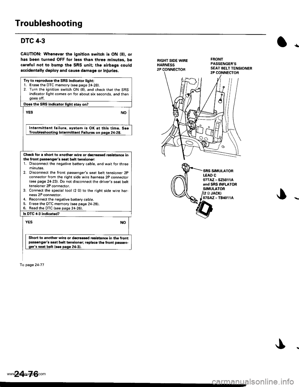
RIGHT SIDE WIREHARNESS2P CONNECTOR
FRONTPASSENGER'S
SRS SIMULATORLEAD C07TM - SZ5011Aand SRS INFLATORSIMULATOR
/2 o JACKIl07sAz - TB4011A
tnat2s>,-ar'--\>
Try lo reproducothc SRS indicator light:'1. Erase the DTC memory (see page 2{-28).2. Turn the ignition switch ON {ll}, and check that the SRSindicator light comes on for about six seconds, and thengoes off.
Doos the SRS indicstor light stay on?
YESNO
Intermittent failure, rystgm ia OK rt this timo. S6cTroubloshooting Intermittont Failu.os on pago 2+28.
Chock to. a short to .nothor wira or decre8od ro3btance inthe froni pa3sengor'3 aoat belt ten3ioner:1. Disconnect the negative battery cable, and wait for threemrnutes.2. Disconnect the front passenger's seat belt tensioner 2Pconnector from the right side wire hamess 2P connector(see page 24-23). Do not disconnect the driver's seat belttensioner 2P connector.3. Connect the special tool (2 O) to the right side wire har-ness 2P connoctor.4. Reconnect the negative battgry cable.5. Erase the DTC memory (see page 24-28).6. Read the DTC lsee page 24-261.
|3 DTC G3 indicatod?
YESNO
Short to .noth6r wire o. dc6e.r€d r€aktanco in the frontpassenger'3 s€at boh teniioner; roplacc the lront pass6n-g6r's aeat belt (s€e psge 2a-31.
To page 24-77
24-76
www.emanualpro.com
Page 1374 of 1395
From page 24-76
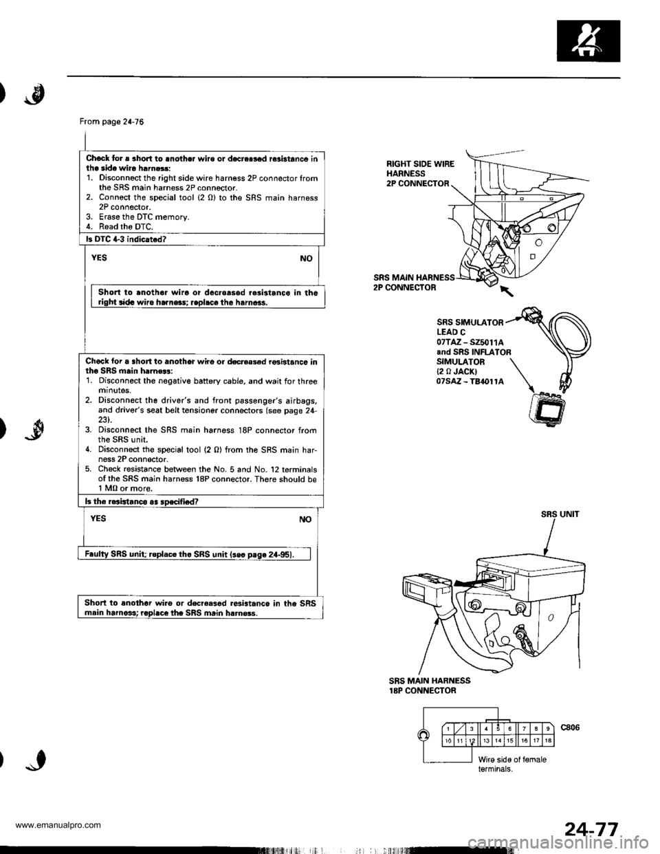
Chock to. a aho.l to lnothcr wire or d€creslod rosbtanco inth. side wiro harn.$:1. Disconnoct the right side wire harness 2P connector lromthe SRS main harness 2P connector.2. Connoct the special tool (2 O) to the SRS main harness2P connector.3. Erase the DTC memory.4. Read tho DTC.
13 DIC +3 indicated?
YESNO
Short to .noth6r wiro or doc.oasod r.sistanco in thGdght sida wiro ha]ne3s; rapl.ce the hamcas.
Chack loi a short to anothor wire o. docreas€d rGbtancc intho SRS main h.]n€$:1. Disconnect the negative battery cable, and wait for threemtnutes,2. Disconnect th6 driver's and front passenger's airbags,and driver's seat belt tensioner connectors (see page 24-
3. Disconnect the SRS main harness 18P connector fromthe SRS unit.4. Disconnect the special tool (2 0) from the SRS main har-ness 2P conn€ctor.5. Check resistance between the No. 5 and No. '12 terminalsof the SRS main harness 18P connector. There should be1 MO or more.
b the raaistanco aa soscifiedT
YESNO
F.ulty SRS unit; roplac€ tho SRS unit lseo pase 24-951.
Short to enothor wi.o or decree3od r*istance in the SRSmain harnoit rophco the SRS main ha.nsss.
RIGHT SIOE WIREHARNESS2P CONNECTOR
SRS MAIN2P CONNECTOR
SRS SIMULATORLEAD C07TAZ - SZ50114and SRS INFLATORSIMULATOR{2 0 JACK)07saz - Ta1ol1A
)
SBS MAIN HARNESS18P CONNECTOR
c806\6
15
l;iid€ of {6maleterminals,
I
24-77
www.emanualpro.com
Page 1375 of 1395
Troubleshooting
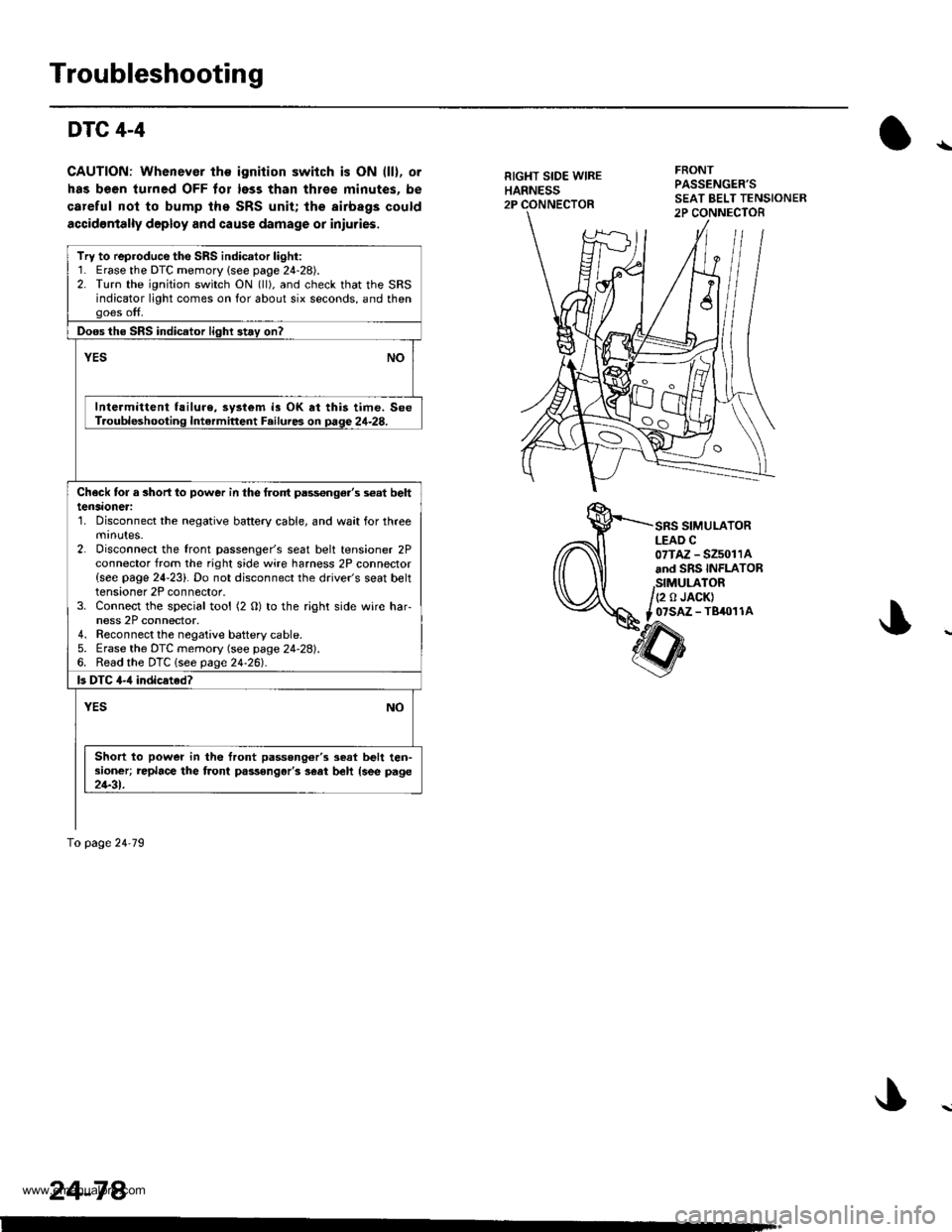
DTC 4-4
CAUTION: Whenever the ignition switch is ON (ll), or
has been turned OFF tor less than thlee minutes. be
careful nol to bump the SRS unit; the airbags could
accidontally deploy and cause damage or iniuries.
RIGHT SIDE WIREHARNESS2P
FRONTPASSENGER'S
SRS SIMULATORLEAD C07TAZ - SZ5011Aand SRS INFLATOR
,StMULATOR/(2 o JACK)
t _07SAZ - TBiro1 1A
Try to reproduce the SRS indicator light:1. Erase the DTC memory {see page 24-28).2. Turn the ignition switch ON (ll), and check that the SRSindicator light comes on for about six seconds, and thengoes off.
Doos the SRS indicator light 3t.y on?
vEsNO
Intermittent f!ilure, system is OK at this time. SeeT.oubleshooting Intermittent F.ilures on page 24-28.
Check tor a 3horl lo power in the frolt pass€nge.'s s€at belttensaoneri'1. Disconnect the negative battery cable, and wait for threemrnutes.2. Disconnect the front passenger's seat belt tensioner 2Pconnector from the right side wire harness 2P connector{see page 24-23}. Do not disconnect the driver's seat belttensioner 2P connector.3. Connect the special tool (2 O) to the right side wire har-ness 2P connector.4. Reconnect the negaiive baftery cable.5. Erase the DTC memory (see page 24-28).6. Read the DTC lsee page24-261.
ls DTC 4-,1 indicated?
YESNO
Short to power in the front passong6r'3 seat belt ten-sioner; replace the front passongar'3 s€at beh {see page21-31.
To page 24'79
24-78.
www.emanualpro.com
Page 1376 of 1395
)
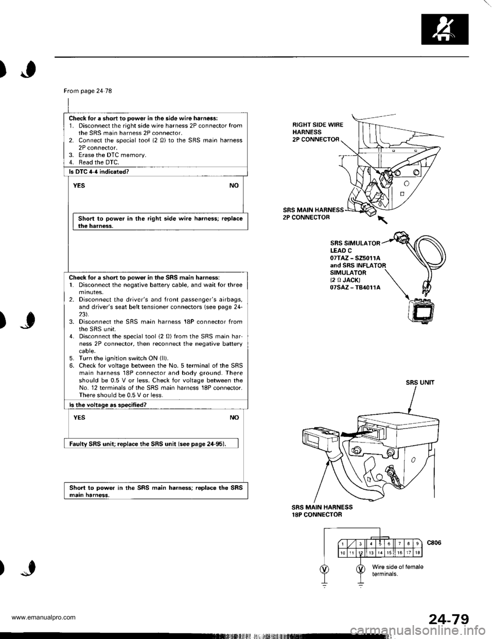
RIGHT SIDE WIREHARNESS2P CONNECTOR
SRS MAIN2P CONNECTOR
SBS SIMULATORLEAD C07TAZ - SZ5011Aand SRS INFLATORSIMULATOR \(2 0 JACK) \07sAz-T84011A \\
)J
)
@
SRS MAIN HARNESS18P CONNECTOR
Ftom page 24 78
Check for a short to power in the side wire harn6s:1. Disconnect the right side wire harness 2P connector fromthe SRS main harness 2P connector,2- Connect the special tool (2 0) to the SRS main harness2P connector.3. Erase the DTC memory.4. Read the DTC.
ls DTC 4-{ indicated?
YESNO
Short to power in the right side wire harness; replacethe harness.
Check tor a short to oow6r in the SRS main harness:1. Disconnect the negative battery cable, and wait for threemtnutes,2. Disconnect the driver's and front passenger's airbags,and driver's seat belt tensioner connectors (see page 24-23).3. Disconnect the SRS main harness 18P connector fromthe sRS unit.4. Disconnect the special tool i2 0) from the SRS main harness 2P connector, then reconnect the negative batterycaore.5. Turn the ignition switch ON (ll).
6. Check for voltage between the No. 5 terminal of the SRSmain harness 18P connector and body ground. Thereshould be 0.5 V or less. Check for voltage between theNo. 12 terminals of the SRS main harness 18P connector.There should be 0.5 V or less.
ls the voltage as specified?
NOYES
Faulty SRS unit; replace the SRS unit (see pase 24-95).
Short to power in the SRS main harness; replace the SRSmain harness.
24-79
www.emanualpro.com