Vehicle speed sensor HONDA CR-V 1998 RD1-RD3 / 1.G Owner's Guide
[x] Cancel search | Manufacturer: HONDA, Model Year: 1998, Model line: CR-V, Model: HONDA CR-V 1998 RD1-RD3 / 1.GPages: 1395, PDF Size: 35.62 MB
Page 779 of 1395

26. Connect the vehicle speed sensor (VSS). the coun-
tershaft speed sensor. and the A,/T gear position
switch connectors,
VEHICLE SPEEO
SPEED SENSOACO'{NECTOR
Connect the lock-up control solenoid valve connec-
tor, then install the harness clamp on the clamp
bracket.
HARNESS CI-AMP
27.
RADIATOR HOSECLAMP
TRANSMISSIONGROUND CAB1ITERMINAL
LOCK-UP OONTROLSOLENOID VALVECONNECTOR
6x1.0mm12 N'm (1.2 kgi.m,8.? tbtftl
28.
29.
Instail the transmission ground cable terminal on
the transmission hanger, and install the radiator
hose clamp on the transmission hanger,
Connect the starter cables to the starter, and install
the harness clamD on the clamD bracket. Make sure
the crimped side of the starter cable ring terminal is
facing out.
STARTEBCABLE
STARTER CAAtf,
Install the air cleaner housing assembly and the
intake air duct.
Refill the transmission with ATF (see page 14-161).
Connect the battery positive terminal and negative
terminal.
Set the parking brake, Start the engine, and shift the
transmission through all gears three times.
Check the shift cable adjustment (see page 14-271]-.
Check the tront wheel alignment and adjust it if
needed (see section 18).
Let the engine reach normal operating temperature
(the radiator fan comes on) with the transmission in
E or N position, then turn it off and check the ATF
level {see page 14-160).
Perform a road test (see page 14-157 and 14-158).
30.
31.
34.
CLAMP BRACKET
37.
14-263
www.emanualpro.com
Page 952 of 1395
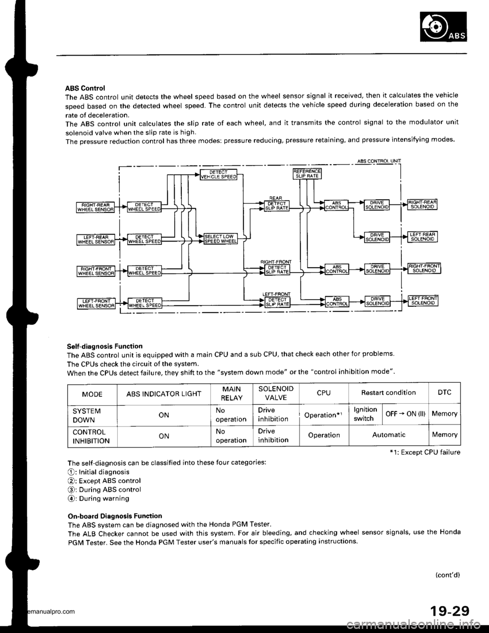
ABS Control
The ABS control unit detects the wheel speed based on the wheel sensor signal it received, then it calculates the vehicle
speed based on the detected wheel speed. The control unit detects the vehicle speed during deceleration based on the
rate of deceleration.
The ABS control unit calculates the slip rate of each wheel, and it transmits the control signal to the modulator unit
solenoid valve when the slip rate is high
The pressure reduction control has three modes: pressure reducing, pressure retaining, and pressure intensi{ying modes.
Self-diagnosis Function
The ABS control unit is equipped with a main cPU and a sub cPU, that check each other for problems.
The CPUs check the circuit of the system.
When the CPUS detect failure, they shift to the "system down mode" or the "control inhibition mode".
The self-diagnosis can be classitied into these four categories:
O: Initial diagnosis
O: Except ABS control
O; During ABS control
@: During warning
On-board Diagnosis Function
The ABS system can be diagnosed with the Honda PGM Tester.
The ALB Checker cannot be used with this system. For air bleeding. and checking wheel sensor signals, use the Honda
PGIM Tester. See the Honda PGM Tester user's manuals for specific operating instructions.
(cont'd)
19-29
ABS CONTROL I-INIT
MODEABSINDICATOR LIGHTMAIN
RE LAY
SOLENOID
VALVERestan conditionDTC
SYSTEM
DOWNONNo
operatron
Drive
inhibitionOperation*rlgnition
switchOFF - oN (ll)Memory
CONTROL
INHIBITIONONNo
operaton
Drive
inhibitionOperationAutomaticlVemory
*1: Except CPU failure
www.emanualpro.com
Page 954 of 1395
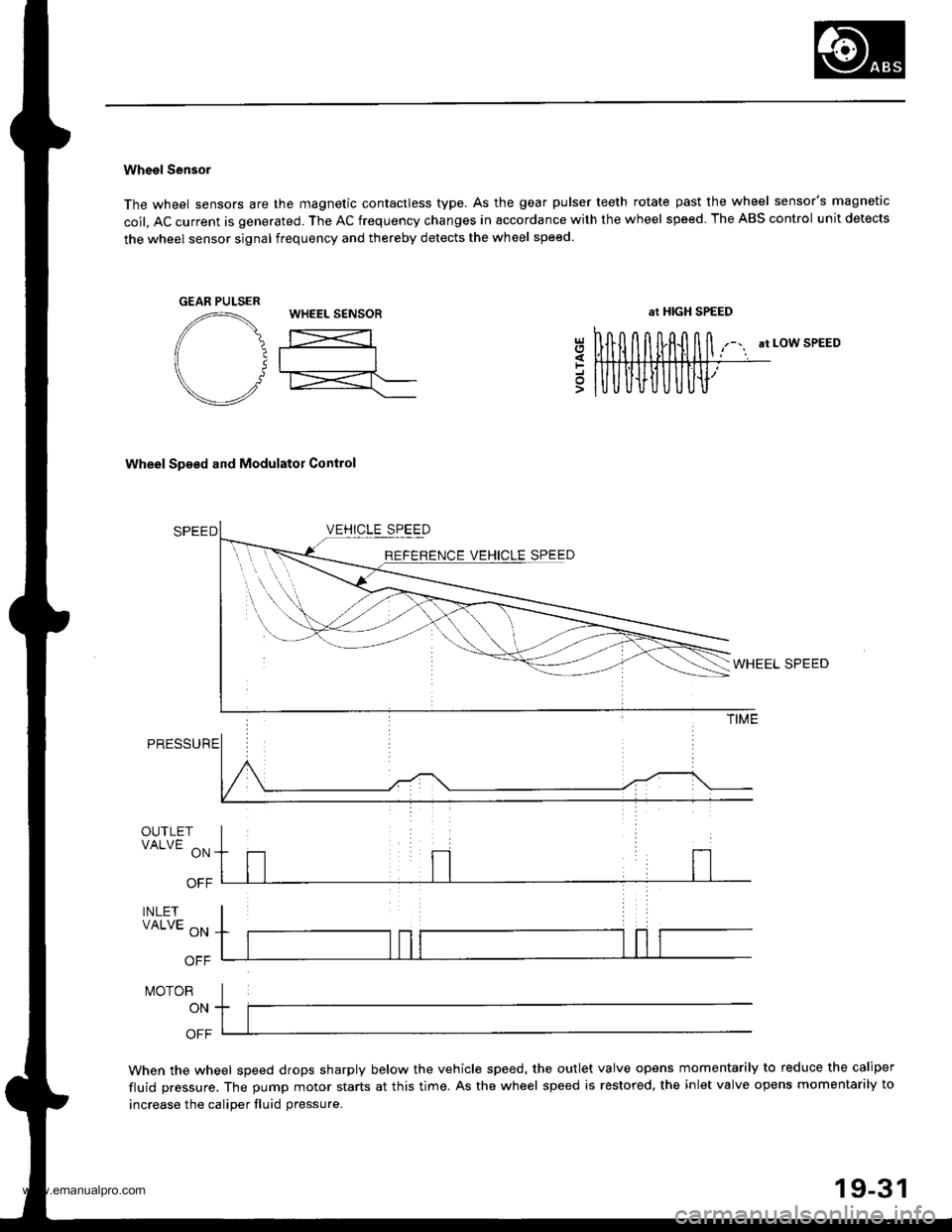
Wheel Sensor
The wheel sensors are the magnetic contactless type. As the gear pulser teeth rotate past the wheel sensor's magnetic
coil, AC current is generated. The AC frequency changes in accordance with the wheel speed. The ABS control unit detects
the wheel sensor signal frequency and thereby detects the wheel speed
at LOW SPEED
wheel Sp€od and Modulatot Control
VEHICLE SPEED
VEHICLE SPEED
WHEEL SPEED
PRESSU
OUTLETVALVE ON
OFF
INLETVALVE ON
OFF
MOTOR
ON
OFF
When the wheel speed drops sharply below the vehicle speed, the outlet valve opens momentarily to reduce the caliper
fluid pressure. The pump motor starts at this time. As the wheel speed is restored. the inlet valve opens momentarily to
increase the caliDer fluid oressure.
F
GEAR PULSER
19-31
www.emanualpro.com
Page 959 of 1395
Troubleshooting Precautions
ABS lndicalor
1 lf the system is oK, the ABS indicator goes off two seconds after turning the ignition switch oN 1l) wathout staningthe engine, and then comes on again and goes off after two seconds. This occurs because the ABS control unit isturned on by the lG2 power source.2. The ABS indicator comes on when the ABS control unit detects a problem in the system. However, even thouoh thesystem is operating properly, the ABs indicator will come on too, under the following conditions:. Signal disturbance
. Wheel spin
. Only drive wheels rotate. Battery voltage fluctuates
To determine the actual cause of the problem, question the customer about the problem, taking these conditions intoconsideration:
3 When a problem is detected and the ABS indicator comes on, the indicator can stay on until the ignition switch isturned OFF, or it can automatically go off, depending on the mode.. Indicator stays on untilthe ignition switch is turned off: When the system is in the system down mode.. Indicator automatically goes off: When the system is in the control inhibition mode.4 The ABS indicator stays on when the system is reactivated without erasing the DTC, but it goes off after starting thevehicle.
When the wheel sensor system is faulty and the ABS indicator comes on. the algorithm of the system automatically turnsoff the ABS indicator after the wheel speed signal returns to the normal speed. Also, when the DTc is erased, the cpu isreset and the ABS indicator goes off when the system checked out normal by the initial diagnosis.Therefore, test-drive the vehicle after servicing the wheel sensor system. and be sure that the ABS indicator does notcome on.
5 When the ABS control unit outputs battery voltage to the gauge assembly, the ABS indicator ooes off.
Diagnostic Trouble Code (DTCI
1. The diagnostic trouble code (DTc) is memorized when a problem is detected and the ABS indicator does not go off,or when the ABS indicator comes on.The DTc is not memorized when the ABS indicator comes on unress the cpu is activated,2 The memory can hold any number of DTCs. However, when the same DTc is detected twice or more, the tater one iswritten over the old one.
Therefore, when the same problem is detected repeatedly, it is recorded as one DTC.3. The DTCs are indicated in the order of ascending number, not in the order they occur.4. The DTCS are memorized in the EEPROM (non-volatile memorv).Therefore, the memorized DTcs cannot be canceled by disconnecting the battery. perform the specified procedures toerase the DTCS.
Self-diagnosis
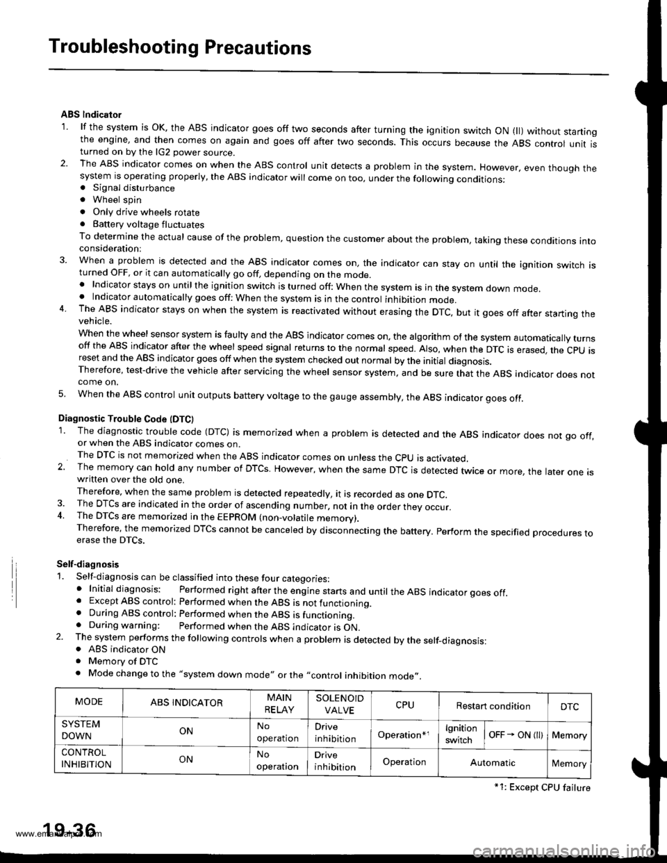
1. Self-diagnosis can be classified into these four categories:' Initial diagnosis: Performed right after the eng ine starts and untir theABS indicator goes off.. Except ABS control: Performed when the ABS is not functioning.. During ABS control: Performed when the ABS is functioning.. During warning: Performed when the ABS indicator is ON.2. The system performs the fo|owing contrors when a probrem is detected by the serf-diagnosis:. ABS indicator ON. Memorv of DTC. Mode changetothe "system down mode,, or the ,,control inhibition mode,,.
MODEABS INDICATORMAIN
RELAY
SOLENOID
VALVECPURestart conditionDTC
SYSTEM
DOWNONNo
operation
Drive
inhibitionOperation*rlgnition
switchoFF - ON l)Memory
CONTROL
INHIBITIONONNo
operal|on
Drive
inhibitionOperationAutomaticlMemory
*1: Except CPU failure
19-36
www.emanualpro.com
Page 1174 of 1395
![HONDA CR-V 1998 RD1-RD3 / 1.G Owners Guide
Connector ldentification and Wire Harness Routing
Engino Wire Harness
Connecto; or
Terminal
Number of
CavitiesLocationConneqts toNotos
c101
c102
c103
c 104
c105
c105
c106
c 107
c 108
c 109
c]10
c1ll HONDA CR-V 1998 RD1-RD3 / 1.G Owners Guide
Connector ldentification and Wire Harness Routing
Engino Wire Harness
Connecto; or
Terminal
Number of
CavitiesLocationConneqts toNotos
c101
c102
c103
c 104
c105
c105
c106
c 107
c 108
c 109
c]10
c1ll](/img/13/5778/w960_5778-1173.png)
Connector ldentification and Wire Harness Routing
Engino Wire Harness
Connecto; or
Terminal
Number of
CavitiesLocationConneqts toNotos
c101
c102
c103
c 104
c105
c105
c106
c 107
c 108
c 109
c]10
c1l'l
c112
c113
c't 14
cl16
cl16
c117
c118
c119
c120
c121
c't22
c't23
c't25
cl26
cl27
cr 28
cl29
c130
c131
c132
c 133
c134
c134
c135
c 136
10
6
1
2
1
2
1
10
20
31
16
22
l0
l0'14
14
1
Left side of engine compartment
Left side of engine compartment
Middle of engine
Middle of engine
Left side of engine compartment
Left side of engine compartment
Middle of engine
Middle of engine
Middle of engine
Middle of engine
Middle of engine
Middle of engine
Middle of engine
Middle of engine
Middle of engine
Middle of engine
Middle of engine
Middle of engine
Middle of engine
Middle of engine
Middle of engine
Right side of engine
Middle of engine
Behind right kick panel
Under right side of dash
Under right side of dash
Under right side of dash
Under right side of dash
Under right side of dash
Right side of engine
Right side of engine
Middle of engine
Middle of engine
Middle of engine
Middle of engine
Middle of engine
Middle of engine
Left side of engine compartment
Middle of engine
Middle of engine
Main wire harness (C304)
Main wire harness (C305):'97 - 98 models
No. 1 fuel injector
Crankshaft speed fluctuation (CKF) sensor
Alternator
Alternator
Engine oil pressure switch
No.2 fuel injector
Evaporative emission (EVAP) purge
control solenoid valve
No. 3 fuel injector
No. 4 fuel injector
Primary heated oxygen sensor(Primary HO2S) (sensor 1)
Radiator fan switch
Coolant temperature sending unit
Engine coolant temperature (ECT) sensor
Mainshaft speed sensor
Lock-up control solenoid valve
Back-up light switch
Shift control solenoid valve
Linear solenoid valve
Countershaft speed sesnsor
Starter solenoid
Distributor
Junction connector
PCM
ECIWPCM
ECM/PCM
ECM/PCM
Main wire harness (C,|:}1)
IVT gear position switch
Vehicle speed sensor (VSS)
Throttle position (TP) sensor
MAP sensor
ldle air control (lAC)valve
lntake air temperature (lAT) sensor
Junction connector
Junction connector
Power steering pressure (PSP) switch
Junction connector
Knock sensor (KS)
A/r
USA
Canada
Alr
AlT
M/'r
Afi
'97mooel
'97 model'98 - 00
mooets
'99 - 00
models
T101
r102
Left side of en0ine companment
Right side of engine compartment
Alternator
Under-hood fuse/relay box
G101Middle of engineEngine ground, via engine wire harness
23-14
www.emanualpro.com
Page 1216 of 1395
Gauge Assembly
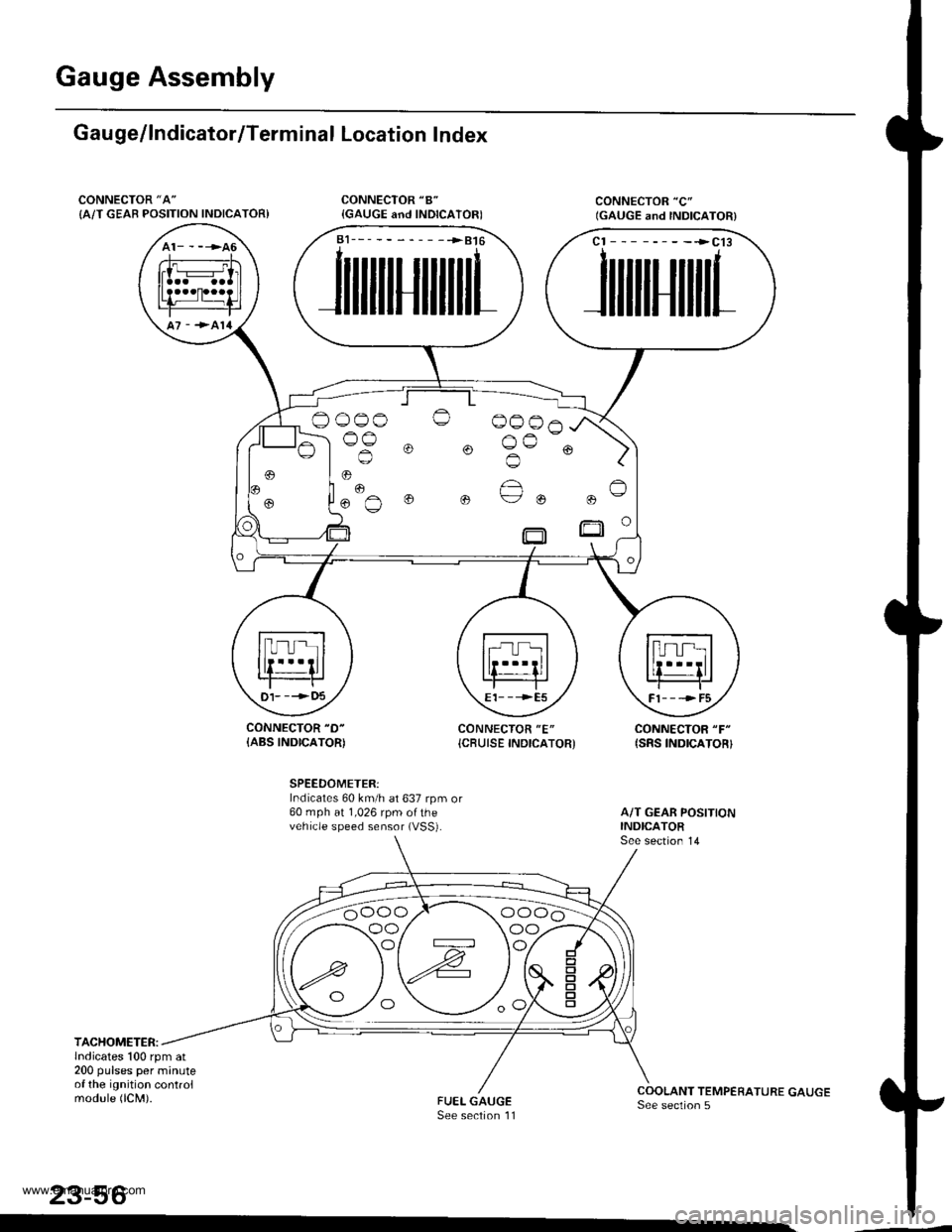
Gau ge/lndicator/Terminal Location Index
CONNECTOR "A"
{A/T GEAB POSITION INDICATOR)
CONNECTOR "D-
{ABS INDICATOR)CONNECTOR "E"
{CBUISE INDICATOR'CONNECTOR "F"
{SRS INDICATOR}
SPEEDOMETER:Indicates 60 km/h at 637 rpm or60 mph at 1,026 rpm ofthevehicle speed sensor (VSS).
TACHOMETER:lndicates 100 rpm at200 pulses per minuteof the ignition controlmodule (lCM).
23-56
a1___-__-____>816
JilililIJililil1
cl --------->cl3
JililtHililL
,
.. "€""^
o o ue ou
t)1- --->t)5E1- - -->E5Fl---->F5
oo/ \oo
www.emanualpro.com
Page 1222 of 1395
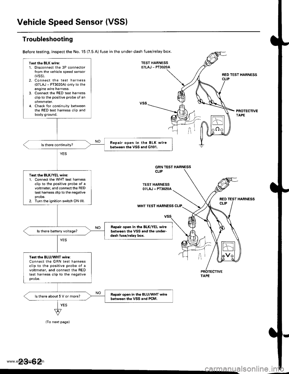
Vehicle Speed Sensor (VSSI
T6st tho BLK wirei1. Disconnect the 3P connectorfrom the vehicle speed sensor{VSS).2. Connect the test harness
{07LAJ - PT3020A) only to theengine wire harness.3. Connect the FED test harnessclip to the positive probe of anohmmeter,4. Check for continuity betweenthe RED test harness clip andbody ground.
Repair open in the BLK wirebetwGon the vSS .nd G101.
T.st the BLK/YEL wire:1. Connect the WHT test harnessclip to the positive probe of avohmeter, and connect the REDtest harness clip to the negativeprobe.2. Turn the ignition switch ON (ll).
Rep.ir op.n in th. BLK/YEL wirebetwaen the VSS rnd the und6r-dash fuse/.6lav box.ls there battery voltage?
Test the BLU/WHT wi.s:Connect the GRN test harnessclip to the posilive probe of avoltmeter. and connect the REDtest harness clip to the negativeprobe.
Repair open in the BLU/WHT wirobstweon the VSS and PCM.ls there about 5 V or more?
Troubleshooting
Before testing, inspect the No. 15 (7.5 A) fuse in the underdash fuse/relay box.
TEST HARNESSOTLAJ - PT3O2OA
RED TEST HARNESS
PROTECTIVETAPE
GRN TEST HARNESSCLIP
TEST HARNESSOTLAJ - PT3O2OA
REOCLIPWHT TEST HARNESS CLIP
(To next page)
23-62
HARNESS
TAPE
www.emanualpro.com