bearing HONDA CR-V 1998 RD1-RD3 / 1.G Owner's Guide
[x] Cancel search | Manufacturer: HONDA, Model Year: 1998, Model line: CR-V, Model: HONDA CR-V 1998 RD1-RD3 / 1.GPages: 1395, PDF Size: 35.62 MB
Page 463 of 1395
Mainshaft Assembly
Clearance Inspection
NOTE; lf replacement is required, always replace the
synchro sleeve and hub as a set.
L Support the bearing inner race with a socket. and
Dush down on the mainshaft.
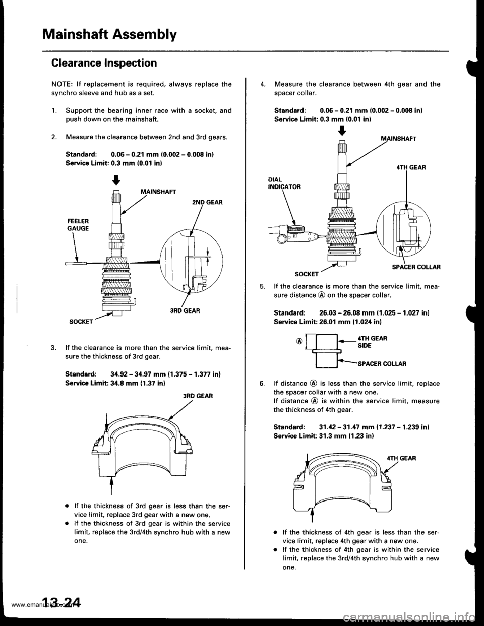
2. Measure the clearance between 2nd and 3rd oears.
Siandard: 0.06 - 0.21 mm 10.002 - 0.008 in)
Servica Limit: 0.3 mm (0.01 in)
lf the clearance is more than the service limit, mea-
sure the thickness of 3rd gear.
Standard: 34.92 - 34.97 mm {1.375 - 1.377 in)
Service Limit 34.8 mm (1.37 in)
3RD GEAR
lf the thickness of 3rd gear is less than the ser-
vice limit, replace 3rd gear with a new one.
lf the thickness of 3rd gear is within the service
limit, replace the 3rd/4th synchro hub with a new
one.
13-24
+
4. Measure the clearance between 4th gear and the
spacer coIar,
Standard: 0.06 - 0.21 mm {0.002 - 0.008 in)
Servic€ Limit: 0.3 mm {0.01 inl
lf the clearance is more than the service limit, mea-
sure distance @ on the spacer collar,
Standard: 26.03 - 26.08 mm {1.025 - 1.027 inl
Service Limit: 26.01 mm {1.02,[ in]
o[-l:-g;;em
fp-rro.ERcoLLAR
6.tf distance @ is less than the service limit, replace
the sDacer collar with a new one.
lf distance @ is within the service limit. measure
the thickness of 4th gear.
Standard: 31.42 - 31.'17 mm 11.237 - L239 inl
Sarvicc Limit:31.3 mm {1.23 in)
lf the thickness of 4th gear is less than the ser-
vice limit, replace 4th gear with a new one.
lf the thickness of 4th gear is within the service
limit, replace the 3rd/4th synchro hub with a new
one,
www.emanualpro.com
Page 465 of 1395
Mainshaft Assembly
Inspection
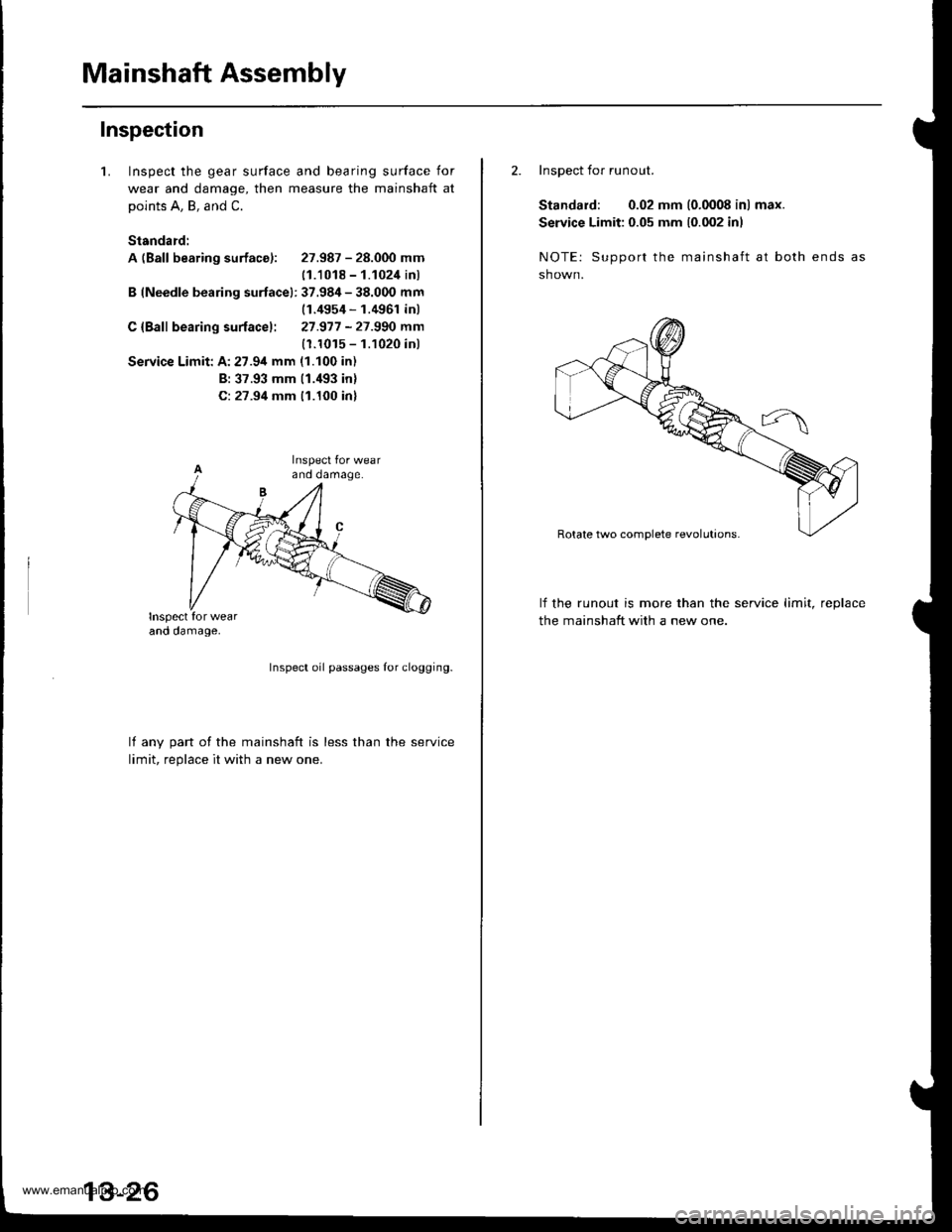
1.Inspect the gear surface and bearing surface for
wear and damage, then measure the mainshaft at
points A, B, and C.
Standard:
A (Ball bearing surface): 27.987 - 28.000 mm
11.1018 - 1.1024 inl
B (Needle bearing surfacel: 37.984 - 38.000 mm(1.4954 - 1.4961 inl
C {Bafl bearing surfacel: 27.977 -27.990 mm
(1.1015 - 1.1020 inl
Service Limit: A:27.94 mm (1.100 in)
B: 37.93 mm (1.'193 inl
C: 27.94 mm 11.100 inl
Inspect oil passages Ior clogging.
lf anv oart of the mainshaft is less than the service
limit. reolace it with a new one.
2. Inspect for runout.
Standard: 0.02 mm (0.0008 in) max.
Service Limit: 0.05 mm 10.002 inl
NOTE: Support the mainshaft at both ends
sh own.
lf the runout is more than the service limit, reDlace
the mainshaft with a new one.
www.emanualpro.com
Page 466 of 1395
Reassembly
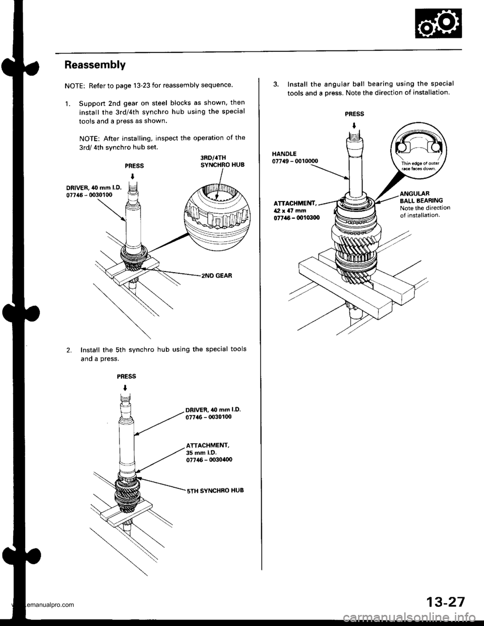
NOTE: Refer to page 13-23 for reassembly sequence.
1. Suppon 2nd gear on steel blocks as shown, then
install the 3rd/4th synchro hub using the special
tools and a press as shown.
NOTE: After installing, inspect the operation of the
3rd/ 4th synchro hub set.
PRESS
I
3RD/4THSYNCHRO HUB
DRIVER, ,l(} mm l.O.
07746 - 0030'�1 00
2.
2NO GEAR
Install the sth synchro hub using the special tools
and a press.
PRESS
I
DRlvER,40 mm l.D.
077{6 - 00301(x)
ATTACHMENT,35 mm l.D.077i16 - lx)3ollx)
sTH SYNCHBO HUB
3. Install the angular ball bearing using the special
tools and a oress. Note the direction of installation.
PRESS
I
077a6 - 0011x100
HANDLE07749 - 0010000
ATTACHMENT,/Vl x a7 mm
BALL BEARINGNote the dirediono{ installation.
13-27
www.emanualpro.com
Page 467 of 1395
Countershaft Assembly
Index
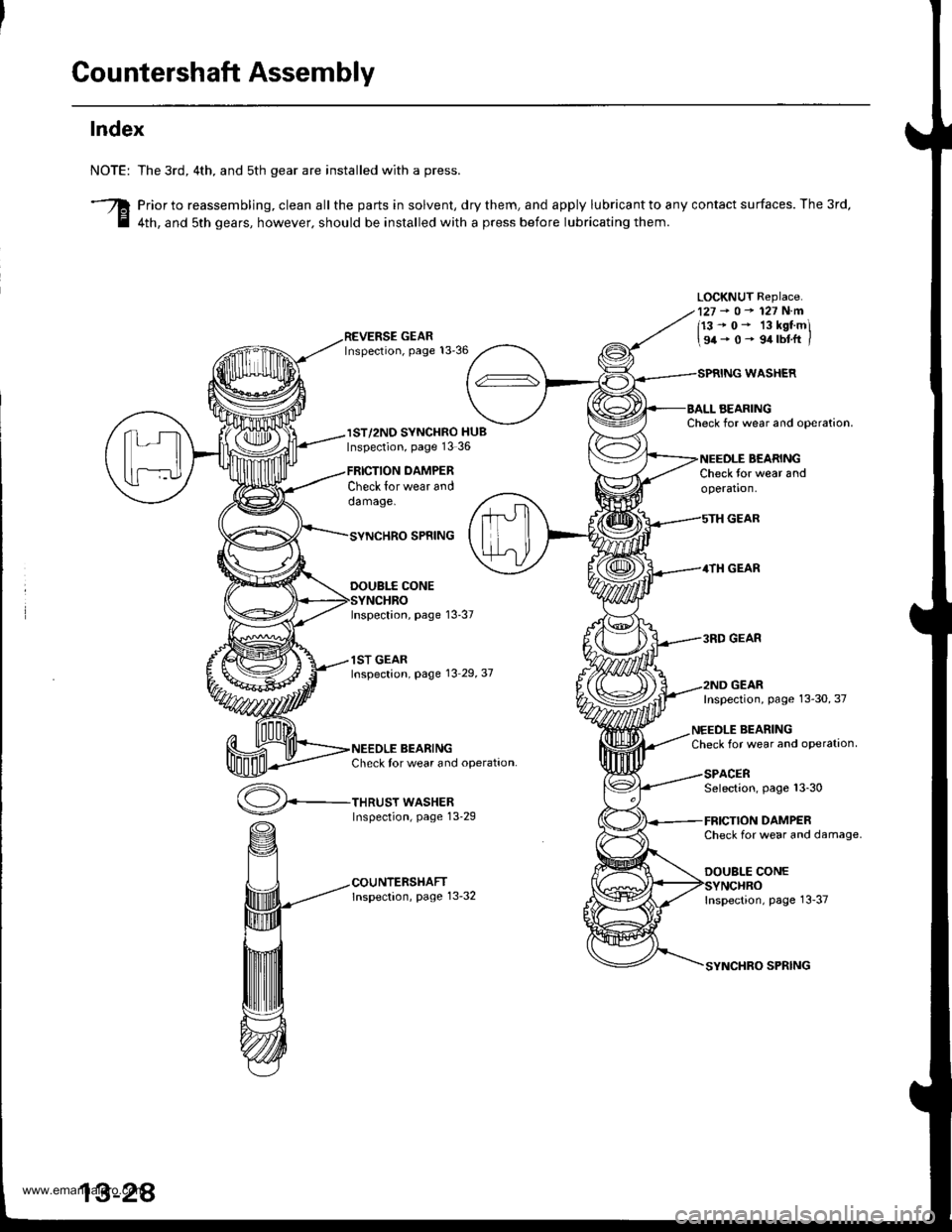
NOTE:
3
The 3rd, 4th. and sth gear are installed with a press.
Prior to reassembling, clean all the parts in solvent, dry them, and apply lubricant to any contact surfaces. The 3rd,
4th, and sth gears, however. should be installed with a press before lubricating them.
LOCKNUT Replace.127-o-127N.m
113-0- 13kstmi
\94-0- 9.trbtft /
IST/2ND SYNCHRO HUBInspection, page 13 36
Check lor wear anddamage.
THRUST WASHERInspection, page 13-29
DAMPER
WASHER
AEARINGCheck for wear and ooeration.
BEARINGCheck for wear andoperation.
GEAR
4TH GEAR
3RD GEAR
GEAR
SPNING
DOUBI.f CONE
Inspection, page 13-37
1ST GEARInspection, page 13 29,37
BEARINGCheck tor wear and operation.
Inspection, page 13-30, 37
NEEDLE BEARINGCheck for wear and oPeration
SPACERSelection, page 13-30
DAMPERCheck for wear and damage.
DOUBLE CONE
Inspection, page 13-37
SPRING
www.emanualpro.com
Page 470 of 1395
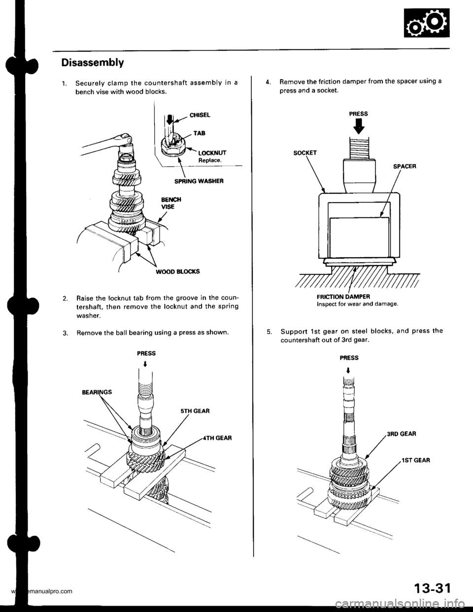
Disassembly
1.
2.
Securely clamp the countershaft assembly in a
bench vise with wood blocks.
SPRIiIG WASHEF
BETICHvtsE
W(X)D BLOCKS
Raise the locknut tab from the groove in the coun-
tershaft, then remove the locknut and the spring
washer.
Remove the ball bearing using a press as shown.
CHISEL
4. Remove the Jriction damper from the spacer using a
press and a socket.
Support lst gear on steel blocks, and press the
countershaft out of 3rd gear.
PRESS
t
5.
PRESS
I
3RD GEAR
1ST GEAR
FRICTION DAMPERInspect lor wear and damage.
13-31
www.emanualpro.com
Page 471 of 1395
Countershaft Assembly
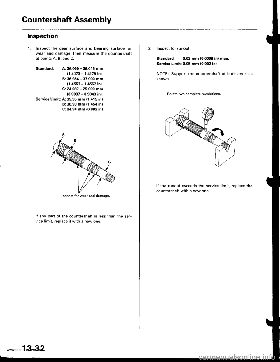
Inspection
1. Inspect the gear surface and bearing surface Ior
wear and damage, then measure the countershaft
at points A, B, and C.
Standa.d:A: 36.000 - 36.015 mm
11.,1173 - f.ill79 inl
B: 36.98/t - 37.000 mm
{r.4561 - 1.4567 inl
C: 24.987 - 25.000 mm
{0.98:17 - 0.9843 inl
Servics Limit: A:35,95 mm (1.'115 in)
B: 36.93 mm (1.454 in)
C: 24.94 mm (0.982 in)
lf anv part of the countershaft is less than the ser-
vice limit. reolace it with a new one.
lnspect for wear and damage.
13-32
2. Inspect for runout.
Standard: 0.02 mm 10.0008 inl max.
Service Limit: 0.05 mm {0.002 inl
NOTE: Support the countershaft at both ends as
shown.
Rotate two complete revolutions.
lf the runout exceeds the service limit, reDlace the
countershaft with a new one.
www.emanualpro.com
Page 472 of 1395
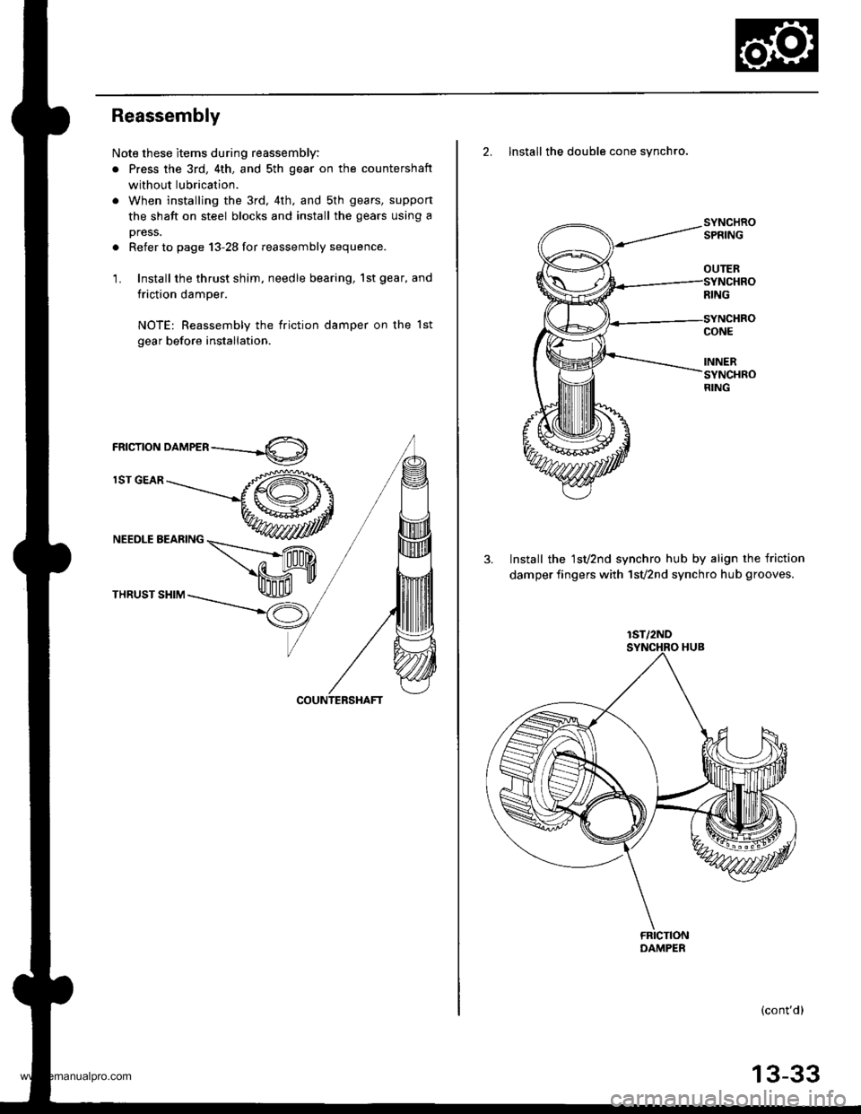
Reassembly
Note these items during reassembly:
. Press the 3rd, 4th, and sth gear on the countershaft
without lubrication.
. When installing the 3rd, 4th. and sth gears, suppon
the shaft on steel blocks and install the gears using a
press.
. Refer to page 13-28 for reassembly sequence.
1. Install the thrust shim, needle bearing, 1st gear, and
friction damper.
NOTE: Reassembly the friction damper on the lst
gear before installation.
rnrcrroru orn,leen ----.-4O)
lST GEAR
NEEDLE BEARING
THRUST SHIM
2. Install the double cone synchro.
3. Install the 1sv2nd synchro hub by align the friction
damper fingers with 1svznd synchro hub grooves.
(cont'd)
OUTER
lST/2ND
13-33
www.emanualpro.com
Page 474 of 1395
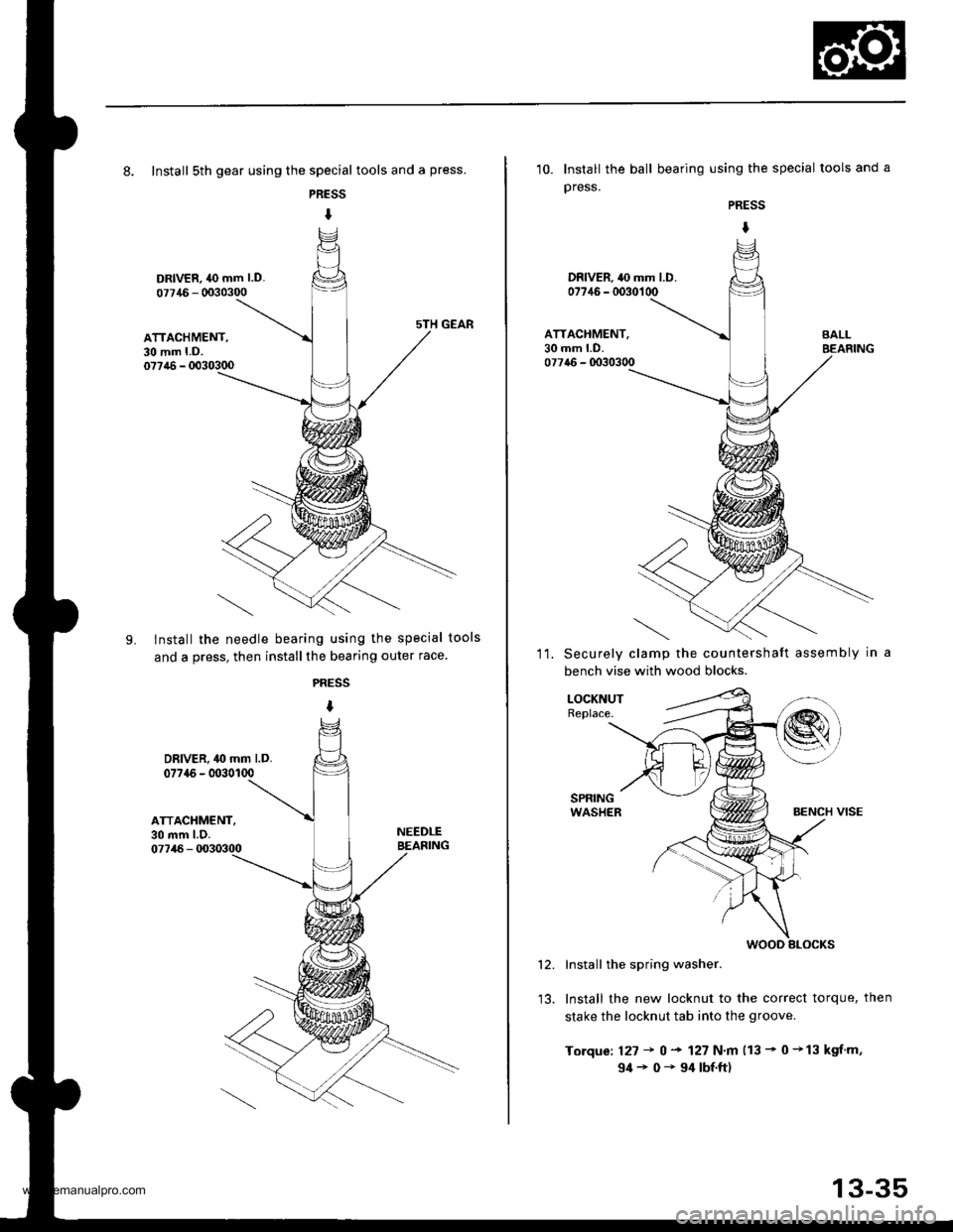
8. Install sth gear using the special tools and a press.
PRESS
I
DRIVER, 40 mm l.D.
07715 - 0030300
ATTACHMENT,30 mm LD.077,16 - 0030300
LInstall the needle bearing using the special tools
and a press, then installthe bearing outer race
PRESS
I
DRIVER. 40 mm l.D.077{6 - 0030100
ATTACHMENT,30 mm l.D.07746 - 0030300
NEEDLEBEASING
10. Install the ball bearing using the special tools and a
press.
PRESS
I
DRIVER. 40 mm LD.07746 - 0030100
ATTACHMENT,30 mm LD.077a6 - 0030300
11.Securely clamp the countershaft assembly in
bench vise with wood blocks.
LOCKNUTReplace.
Install the spring washer.
Install the new locknut to the correct torque, then
stake the locknut tab into the groove.
Torque: 127 + 0 + 127 N.m 113 - 0 +13 kgf.m,
94+0-94|bf.ft)
12.
wooD slocKs
13-35
www.emanualpro.com
Page 477 of 1395
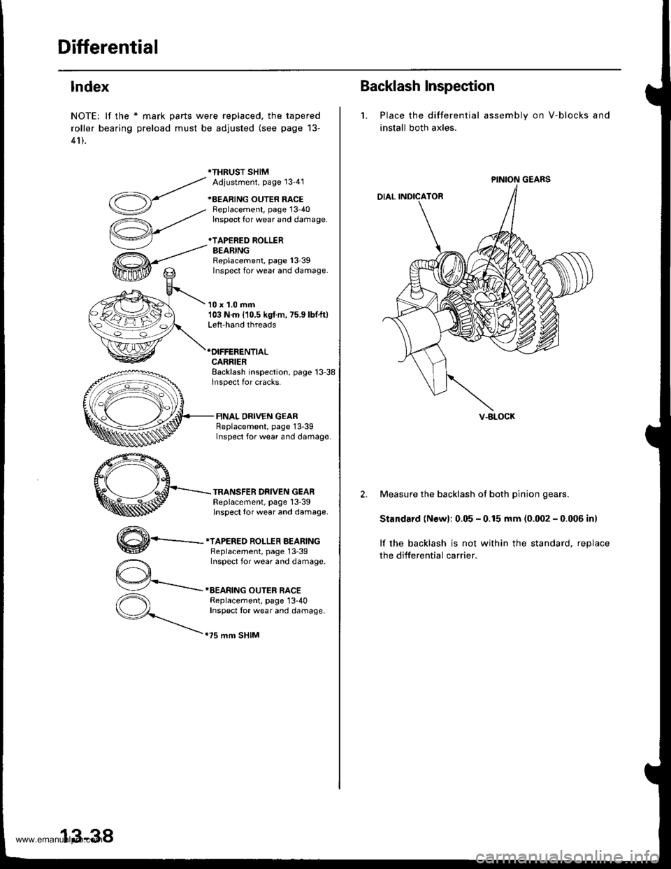
Differential
lndex
NOTE: lf the * mark parts were replaced, the tapered
roller bearing preload must be adjusted (see page 13-
41).
*THRUST SHIMAdiustment, Page 13'41
+BEARING OUTER RACEBeplacement, page 13 40Inspect for wear and damage.
*TAPERED ROLLERBEARINGReplacement, page l3-39Inspect for wear and damage.
10 x 1.0 mm103 N.m {10.5 kgf m, 75.9 lbf.ft}Left-hand threads
CARRIERBacklash inspection, page 13 38lnspect for cracks.
FINAL DRIVEN GEARReplacement, page 13-39Inspect for wear and damage
TRANSFER DRIVEN GEARReplacement, page 13-39Inspect {or wear and damage.
,,4\
W-
*TAPERED ROLLER BEARINGBeplacement, page 13'39Inspect for wear and damage.
IEEARING OUTER RACEReplacement, page 13-40Inspect for wear and damage.
.75 mm SHIM
13-38
Backlash Inspection
1. Place the differential
install both axles.
assembly on V-blocks and
PINION GEARS
V-BLOCK
2. Measure the backlash ot both pinion gears.
Standard (Newl: 0.05 - 0.15 mm (0.002 - 0.006 inl
lf the backlash is not within the standard, reolace
the differential carrier.
www.emanualpro.com
Page 478 of 1395
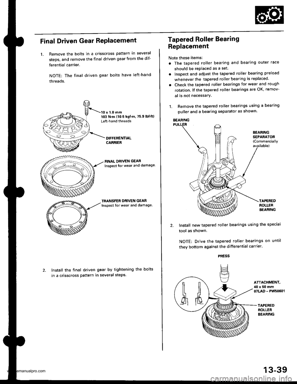
Final Driven Gear RePlacement
LRemove the bolts in a crisscross pattern in several
steps, and remove the final driven gear from the dif-
ferential carrier.
NOTE: The final driven gear bolts have left-hand
threads.
10 x 1.0 mm103 N.m (10.5 kgf m,75.9lbf'ftlLeft'hand threads
FINAL DRIVEN GEAR
lnsoect {or weal and damage
TRANSFER ORIVEN GEARInspect for wear and damage.
Install the final driven gear by tightening the bolts
in a crisscross pattern in several steps.
Tapered Roller Bearing
Replacement
Note these items:
. The tapered roller bearing and bearing outer race
should be replaced as a set.
. Inspect and adiust the tapered roller bearing preload
whenever the tapered roller bearing is replaced'
. Check the tapered roller bearings for wear and rough
rotation. lf the tapered roller bearings are OK, remov-
al is not necessary.
1. Remove the tapered roller bearings using a bearing
puller and a bearing separator as shown.
Install new tapered roller bearings using the special
tool as shown.
NOTE: Drive the tapered roller bearings on until
they bottom against the differential carrter.
PRESS
IJ
BEARINGSEPAFATOB{Commercially
ATTACHMENT,,10 x 50 mm07LAD - PWs060 l
BEARING
13-39
www.emanualpro.com