HONDA CR-V 1998 RD1-RD3 / 1.G Owner's Guide
CR-V 1998 RD1-RD3 / 1.G
HONDA
HONDA
https://www.carmanualsonline.info/img/13/5778/w960_5778-0.png
HONDA CR-V 1998 RD1-RD3 / 1.G Owner's Guide
Page 1244 of 1395
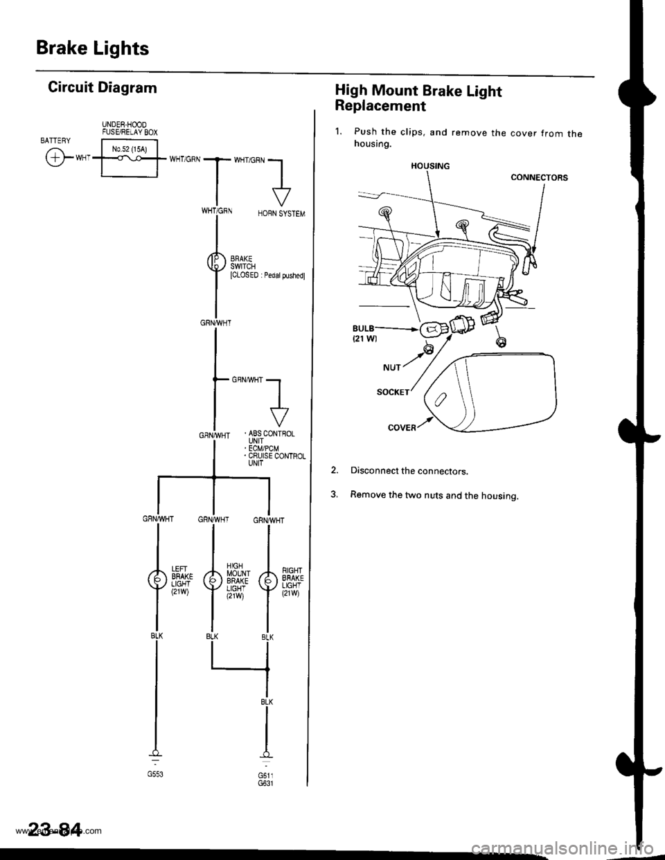
Brake Lights
High Mount Brake Light
Replacement
1. Push the clips, and remove the cover from thehousing.
Disconnect the connectors.
Remove the two nuts and the housing.
2.
HOUSING
Gircuit Diagram
UNDER.HOODFUSE/RELAY BOXBATTENY
/,i | No.s2 {15A) |
\Y*-I=f*-'o*T*'no"l
IV
T:,^-,
HORNSYSTEM
I
i.t53l| *",*"",
GRNA,VHT
GBNMHT -.1
I
I
. ABS CONTFOLUNIT' ECM/PCM. CRUISE CONTROLUNIT
GRNAVHT GRNWH
ll
tl
A[$^Jlr A
Yi,?'il Y
tlBLK BLK
llrl
IBLK
I
I
d
oi,,
RIGHTEFAKELIGHT(21w)
LEFIBFAKELIGHT(2rw)
BLK
G553
23-84
www.emanualpro.com
Page 1245 of 1395
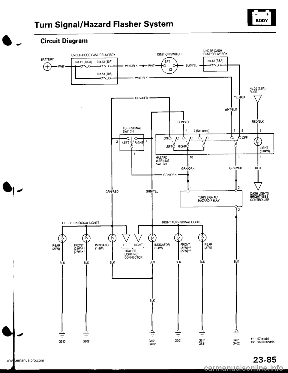
Turn SignallHazard Flasher System
UNDEF HOOD FUSE/NELAY BOX
N0.30 (7.54)FUSE
V
IREO/BLK
l,
t'IFqD
.+
DASH LIGHTSBSIGHTNESSCONTROLLER
HAZARDWARNINGswtTcH
_ GRN/ORN
YEUBLK
WHTiELK
GRNAVHT
O -. Circuit Diagram
BATTEFY
@**'
q-
103
GRN/ORN
INDICATOR
TFAILERLIGHTINGCONNECTOR
INDICATOR(1.4W)
BLK
G553
IGN T]ON SWITCHUNDER.OASHFUSE/RELAY BOX
No 12 (7.sA)
l----r-l-----i-F-- --------_ \
BtK
G401G402
:i1r'97model*2 :'98-00 models
23-85
www.emanualpro.com
Page 1248 of 1395
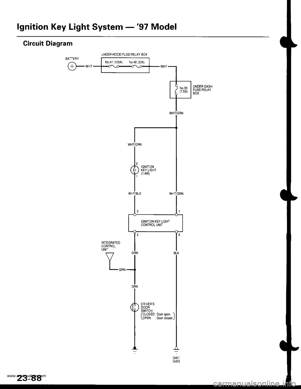
lgnition Key Light System -'97 Model
Circuit Diagram
IJNDER-HOOD FUSE/HELAY BOXBATEBY l-Noj',roo{ l;;f
tF*-'--ff::f-*"-l
.l-----
| ; )"t li|illsx"r
I
WNT/GRN
WHT/CRN
I
,k ,0r,, o,u( P I KEYLGHT
Y
{14w)
IWHT/BLK
OR VER'S000R9!rl9rl^ ^I ULU5EU:UOOrOpen I(OPEN :Door dosed J
www.emanualpro.com
Page 1250 of 1395
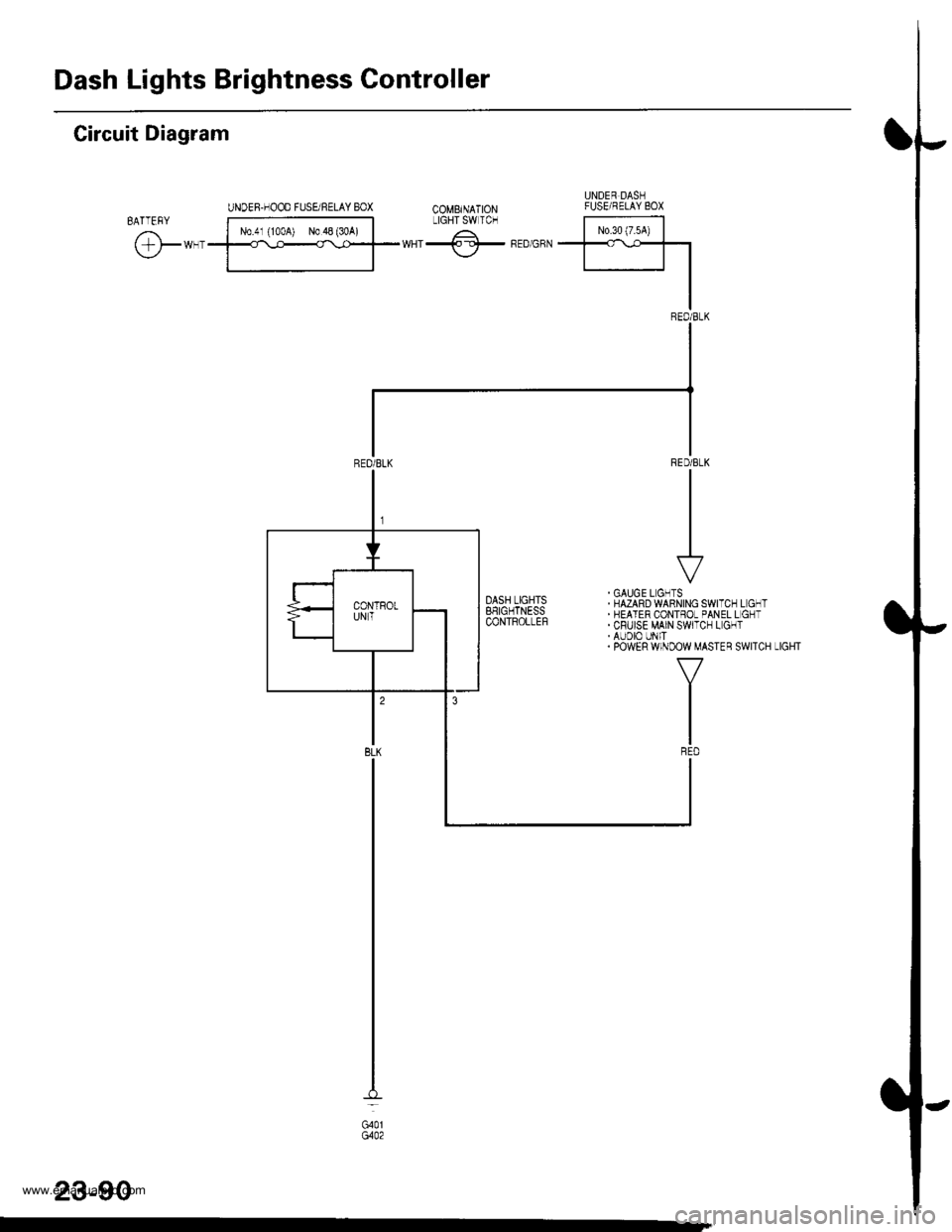
Dash Lights Brightness Controller
Circuit Diagram
23-90
G401
www.emanualpro.com
Page 1253 of 1395
IJ
o-,
lJ
Circuit Diagram
UNOER.I]OOO FUSERELIY BOXBA--FqY [t..*;;;;l
\:/-*-.........-='_Fn-'.,,
t_* d,*^*
I
r"$$i,,,,,*,,
Iii{il''
"r**I
lt
I
.-" Iuffi**,".",
-
LTG
(I/f\\9/I FRoNTI PASSENGEF'S| 0@R) | swrlcNJ lTcLosED D@'
l!oPEN:D@'I
I
I
IrJ----r
I Y l^,,o.orro| | | coNthoL
I F#l*'
FI
INDCATOF!ICH'I
f7
IIIBLU/EL(
23-93
ftrr
www.emanualpro.com
Page 1255 of 1395
Accessory Socket
IGNITION SWITCH
Circuit Diagram
UNDER_HOOO FUSE/RELAY 8OX
o-.
l-
lJ
txt
Fffi^-.rr-.rrl 6\
t-'**1*fffiT wHT'BrK +*HT-137F wHr BLK
| -*T]
UNDER-DASHFUSE/RELAYBOX
YEL/GflN RED/BLK
lt
tl
tl
$Ni*" t-*r-
tl8LK 8LK
tl
ll-:a -:
G401 G40tG4A2 G4A2
J-i,_,
l ft- € l333iEi.''' 'l
I
'"*'
,*1. I
tl
ir*?:r"$
|
tlBLK 8LK
tl
lt-l
G553 G40tG4A2
IREO/GRN
(
) No.6
i{10A)
II
i ll%ti i l9:,'3
IT
YEL
I/BLK YEL/GRN YEL,
GRN
23-95
www.emanualpro.com
Page 1258 of 1395
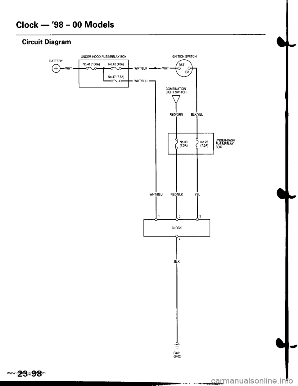
Glock -'98 - 00 Models
Circuit Diagram
BATTERY
@-*"
UNDEE,HOOD FUSE/RELAY BOX
No.41(1004) N0.42140A)-l
N0.47 (7.54)
UNOEN.DASHFUSgFELAY8ox
IGN TION SWlTCH
23-98
G40tG402
www.emanualpro.com
Page 1261 of 1395
E
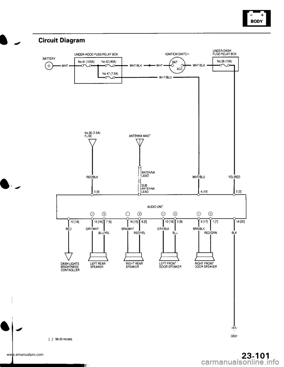
t J Circuit Diagram
UNDER.HOOO FUSE/FELAY BOXUNOEB,DASHFIJSE/RELAY BOX
l-^*"-l
T'5 1-T
I
I
I
I
I
IYEURED
No.30 (7.5A)FUSE
WHT,tsLK
BRN/BLK
s tr4 | 1 l7l
a,-,
1s l16l| 7[61
GHY,ryVHT
IGNITION SWITCH
AUOIO UNIT
oo oo
LEFT REARSPEAKERRIGHT BEARSPEAKERLEFI FRONTDOOF SPEAKERRIGHT FBONTDOOB SPEAKER
23-101
www.emanualpro.com
Page 1265 of 1395
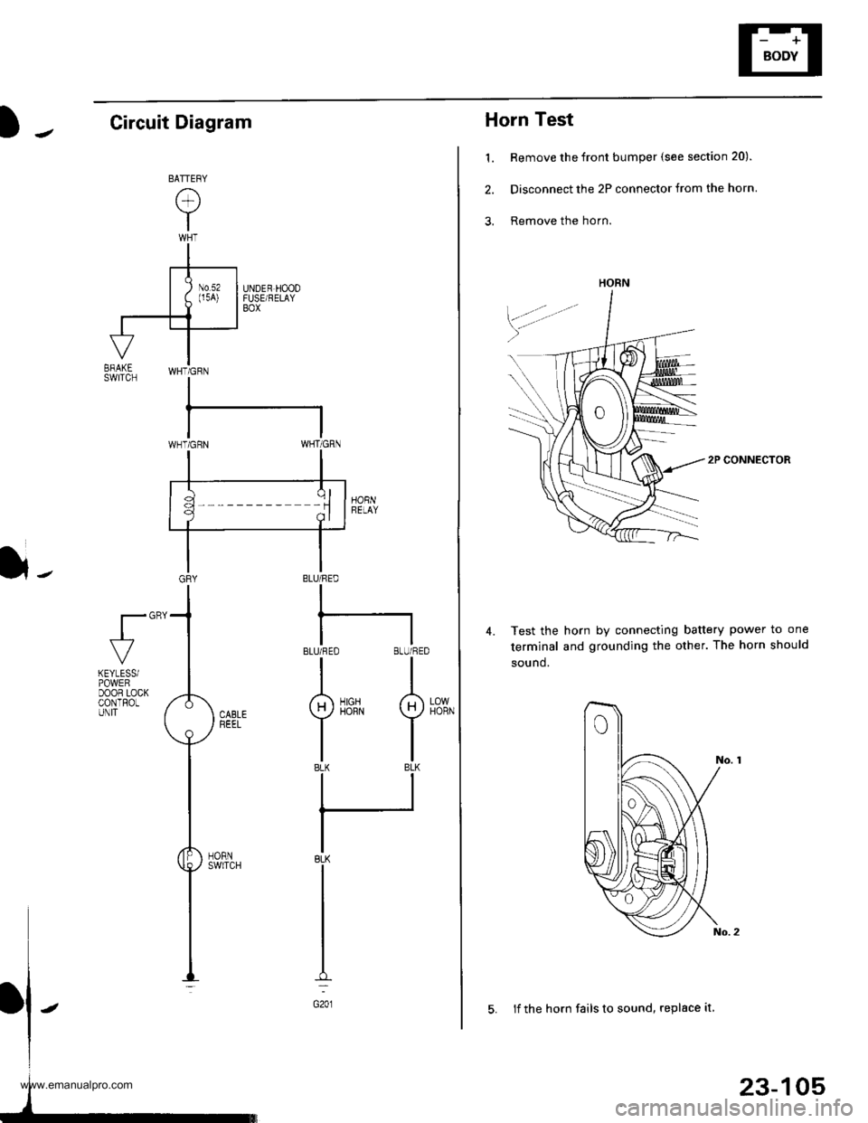
Horn Test
1. Remove the front bumper (see section 20).
2. Disconnect the 2P connector from the horn
3, Remove the horn.
2P CONNECTOR
Test the horn by connecting battery power to one
terminal and grounding the other. The horn should
sound.
4.
HORN
23-105
5. lf the horn fails to sound, replace it
Circuit Diagram
}-BLU/FED
I
BLUi FEO BLU/RED
II
g)iirrN I
tlBLK BLK
ll
IBLK
I
I
I
G201
fl"'
LOWHORN
KEYLESSiPOWEFDOOR LOCKCONTROLUNIT
www.emanualpro.com
Page 1267 of 1395
Power Mirrors
Circuit Diagram
IGNITION SWITCH
lBAI \-€l ^rc2l.Y
YEL
I
-t----t
I lu.'x I
IBLKIryEL
@"*'
POWEN MIRRON SWTCH
UNDER,DASHFUSE/RELAYB0x
GRN vHT +l
35
BLK
-:
G551
l,-
[ ] : '9&00 rnodels
UNDER.HOOD FUSURELAY BOX
N0.41 (100A) N0.42 (40A)WHT/8LK +WHT
YEUREDBLUMHT
-
23-107
www.emanualpro.com
![HONDA CR-V 1998 RD1-RD3 / 1.G Owners Guide
IJ
o-,
lJ
Circuit Diagram
UNOER.I]OOO FUSERELIY BOXBA--FqY [t..*;;;;l
\:/-*-.........-=_Fn-.,,
t_* d,*^*
I
r"$$i,,,,,*,,
Iii{il
"r**I
lt
I
.-" Iuffi**,".",
-
LTG
(I/f\\9/I FRoNTI PASSENGEFS| HONDA CR-V 1998 RD1-RD3 / 1.G Owners Guide
IJ
o-,
lJ
Circuit Diagram
UNOER.I]OOO FUSERELIY BOXBA--FqY [t..*;;;;l
\:/-*-.........-=_Fn-.,,
t_* d,*^*
I
r"$$i,,,,,*,,
Iii{il
"r**I
lt
I
.-" Iuffi**,".",
-
LTG
(I/f\\9/I FRoNTI PASSENGEFS|](/img/13/5778/w960_5778-1252.png)
![HONDA CR-V 1998 RD1-RD3 / 1.G Owners Guide
Accessory Socket
IGNITION SWITCH
Circuit Diagram
UNDER_HOOO FUSE/RELAY 8OX
o-.
l-
lJ
txt
Fffi^-.rr-.rrl 6\
t-**1*fffiT wHTBrK +*HT-137F wHr BLK
| -*T]
UNDER-DASHFUSE/RELAYBOX
YEL/GflN RED/BLK
lt
t HONDA CR-V 1998 RD1-RD3 / 1.G Owners Guide
Accessory Socket
IGNITION SWITCH
Circuit Diagram
UNDER_HOOO FUSE/RELAY 8OX
o-.
l-
lJ
txt
Fffi^-.rr-.rrl 6\
t-**1*fffiT wHTBrK +*HT-137F wHr BLK
| -*T]
UNDER-DASHFUSE/RELAYBOX
YEL/GflN RED/BLK
lt
t](/img/13/5778/w960_5778-1254.png)
![HONDA CR-V 1998 RD1-RD3 / 1.G Owners Guide
Power Mirrors
Circuit Diagram
IGNITION SWITCH
lBAI \-€l ^rc2l.Y
YEL
I
-t----t
I lu.x I
IBLKIryEL
@"*
POWEN MIRRON SWTCH
UNDER,DASHFUSE/RELAYB0x
GRN vHT +l
35
BLK
-:
G551
l,-
[ ] : 9&00 rnodels
U HONDA CR-V 1998 RD1-RD3 / 1.G Owners Guide
Power Mirrors
Circuit Diagram
IGNITION SWITCH
lBAI \-€l ^rc2l.Y
YEL
I
-t----t
I lu.x I
IBLKIryEL
@"*
POWEN MIRRON SWTCH
UNDER,DASHFUSE/RELAYB0x
GRN vHT +l
35
BLK
-:
G551
l,-
[ ] : 9&00 rnodels
U](/img/13/5778/w960_5778-1266.png)