fuse HONDA CR-V 1998 RD1-RD3 / 1.G Owner's Guide
[x] Cancel search | Manufacturer: HONDA, Model Year: 1998, Model line: CR-V, Model: HONDA CR-V 1998 RD1-RD3 / 1.GPages: 1395, PDF Size: 35.62 MB
Page 405 of 1395
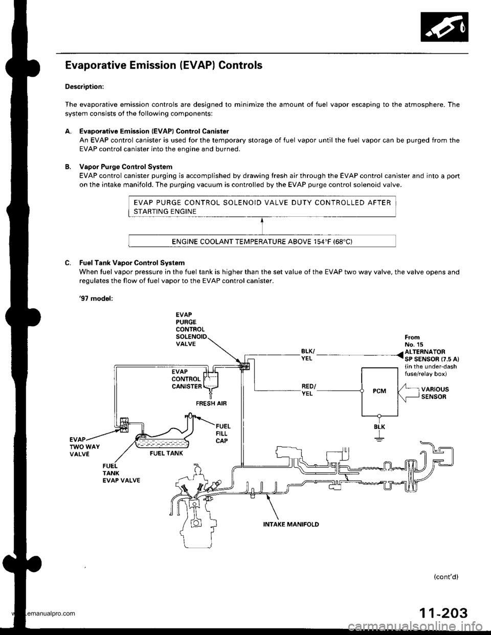
EVAP PURGE CONTROL SOLENOID VALVE DUTY CONTROLLED AFTER
STARTING ENGINE
ENGINE COOLANT TEMPERATURE ABOVE 154"F (68'C)
Evaporative Emission (EVAP) Controls
Description:
The evaporative emission controls are designed to minimize the amount of fuel vapor escaping to the atmosphere. The
system consists of the following components:
A. Evaporative Emission (EVAPI Control Canister
An EVAP control canister is used for the temporary storage of fuel vapor until the luel vapor can be purged from the
EVAP control canister into the enqine and burned.
B. Vapor Purge ConirolSystem
EVAP control canister purging is accomplished by drawing fresh air through the EVAP control canister and into a pon
on the intake manifold. The purging vacuum is controlled by the EVAP purge control solenoid valve.
C. Fuel Tank Vapor Control System
When fuel vapor pressure in the fuel tank is higher than the set value of the EVAP two way valve, the valve opens and
regulates the flow ot fuel vapor to the EVAP control canister.
'97 model:
EVAPPURGECONTROL
VALVEFromNo. 15BLK/ /ALTERNATORYEL I sP SENSOR r7.s At(in the under-dashfuse/relay box)
VARIOUSSENSORFEESH AIF
BLK
I
FUEI- TANK
(cont'd)
11-203
INTAKE MANIFOLD
www.emanualpro.com
Page 407 of 1395

'97 model:
The scan tool indicates Diagnostic Trouble Code (DTC) P0441: Evaporative Emission (EVAP) control system
insufficient purge flow.
Description
By monitoring the purge line vacuum with the MAP sensor, the PCM can detect insufficient EVAP control system purge
flow.
Possiblo Cause
. EVAP Purge Control Solenoid Valve
. EVAP Purge Control Solenoid Valve Circuit
. EVAP Control Canister
. Vacuum Lines
. PCM
Troubleshooting Flowchart
EVAP PURGE CONTROL
SO1TNOID VALVE 2P
CoNNECTOR (C108)
(v)
YL
Wire side of female
termrnals
(cont'd)
11-205
Th€ MIL has b€en reooited on.DTC P0441 is .tored.
Problem verificationl1. Start the engine. Hold theengine at 3,000 rpm with noload (in Park or neut.al) untilthe radiator fan comes on.2. Do the PCM Reset Procedure.3. Connect the SCS service con-nector,4. Test drive under following con'ditions on the road.- without any electrical load- Transmission in @ or @position- Engine speed between1 ,2OO - 2,4OO rpfi.- Decelerate from 50 mph (80
km/h)to 15 mph (24 km/h)Intermittent trilure, sydern is OKat this time. Check for Door con-nections or loose wir€3 at C108
IEVAP purge control solonoidvalvol .nd at the PCM.
ls DTC P0441 indicated?
Check tor an open in the wire (lcl
linel:1. Turn the ignition switch OFF.2. Disconnect the EVAP purge
control solenoid valve 2P con-nector.3. Turn the ignition switch ON (ll).
4. Measure voltage between bodyground and the EVAP purge
control solenoid valve 2P con-nector terminal No. '1,
R€pafu open in thc wir6 b€tw€enthG EVAP purge control solenoidvalve and the No. 15 ALTEBNA-TOR SP SENSOR (7.5 A)fuse.
ls there batlery voltage?
(To page 11'206)
www.emanualpro.com
Page 564 of 1395
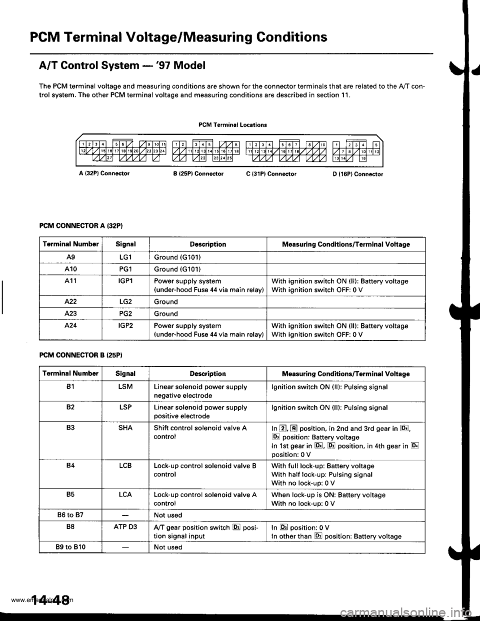
PGM Terminal Voltage/Measuring Conditions
A/T Control System -'97 Model
The PCM terminal voltage and measuring conditions are shown for the connector terminals that are related to the Ay'T con-
trol system. The other PCM terminal voltage and measuring conditions are described in section 11.
PCM Terminal Locations
A {32P} ConnectorB (25P1 ConnectolC {31PI ConnectorD {16P}Connector
PCM CONNECTOR A {32P}
FCM CONNECTOR B (25P)
Torminal NumbcrSignslDescriptionMeasuring Conditions/Terminal Vohage
A9LG1Ground (G101)
A10PG1Ground {G101)
At1IGPlPower supply system(under-hood Fuse 44 via main relav)
With ignition switch ON (ll): Battery voltage
With ignition switch OFF: 0 V
422Ground
Ground
424IG P2Power supply system(under-hood Fuse 44 via main relav)
With ignition switch ON (ll): Battery voltage
With ignition switch OFF: 0 V
Terminal NumberSignalDescriptionMeasuring Conditions/Terminal Vohage
B1LSMLinear solenoid power supply
negative electrode
lgnition switch ON (ll): Pulsing signa
82LSPLinear solenoid power supply
positive electrode
lgnition switch ON (lll: Pulsing signa
B3SHAShift control solenoid valve A
control
In @, @ position, in 2nd and 3rd gear in E,
E position: Battery voltage
In 1st gear in E. F! position, in 4th gear in E
position: 0 V
B4LCBLock-up control solenoid valve B
control
With full lock-up: Battery voltage
With half lock-up: Pulsing signal
With no lock-up: 0 V
B5LCALock-up control solenoid valve A
control
When lock-up is ON: Baftery voltage
With no lock-up: 0 V
86 to 87Not used
B8ATP D3,VT gear position switch E posi-
tion signal input
In E position: 0V
In other than E position: Battery voltage
89 to 810Not used
14-48
www.emanualpro.com
Page 565 of 1395

PCM CONNECTOR B (25P) lcont'd)
PCM CONNECTOR C {31PI
PCM CONNECTOR D II6PI
Terminal NumbelSignalDescriptionMeasuring Conditions/Terminal voltage
811SHBShift control solenoid valve B
control
In E, E position, in 1st and 2nd gear in -q,
Er position: Battery voltage
In B position, in 3rd gear in qd, q:l,in atn
gear in D. position: 0 V
812ILUlnterlock controlWhen ignition switch is ON (ll), brake pedal
deDressed and accelerator oedal released:0 V
B13D4 INDD4 Indicator light controlWhen ignition switch is first turned ON (ll): 6 V
or more for tlvo seconds
In lDll position: 6V or more
814NMSGMainshaft speed sensor ground
815NMMainshaft speed sensor signal
InpuI
Depending on engine speed: Pulsing signal
When engine is stopped: 0 V
816ATP RAy'T gear position switch Eposition signal input
In E position; OV
In other than E position: Battery voltage
817ATP 2Ay'T gear position switch E posi-
tion signal input
InEposition:0V
In other than E position: Battery voltage
B18ATP 1A/T gear position switch El posi-
tion signal input
InEposition:0V
In other than E position: Battery voltage
819 to 821Not used
B�22NCSGCountershaft speed sensor ground
NCCountershaft speed sensor signal
Inpur
Depending on vehicle speed: Pulsing signal
when vehicle is stooped: 0 V
824ATP D4A/T gear position switch iql posi-
tion signal input
In E position: 0V
In other than lgal position: Baftery voltage
825ATP NPAy'T gear position switch E and
N position signals input
In E and E positions: 0V
In otherthan @ and ffi positions:5 V
Terminal NumberSignalDescriptionMeasuring Conditions/Terminal Voltage
SCSService check signalWith ignition switch ON (ll) and service check
connector open: 5 V
With ignition switch ON (ll) and service check
connector connected with special tool: 0 V
c10VBUBack-up power system(under-hood Fuse 47)
Always battery voltage
Terminal NumberSignalDescriptionMeasuring Conditions/Terminal Voltage
STOP SWBrake switch signal inputBrake pedal pressedr Battery voltage
Brake pedal released: 0 V
14-49
www.emanualpro.com
Page 566 of 1395
![HONDA CR-V 1998 RD1-RD3 / 1.G Owners Guide
PCM Circuit Diagram (A/T Gontrol System)
98 Model
UNOEF-HOOO FUSAFELAY sox
_YEL_
09 lD0 lDl,l lDl5
PNK BLU
F rronr
f-r------}-er
F_ cRN _______]_f- PN(
F_ GFNTBLX
F_ gnN
*,,,,)83HfL
f *-> 311 HONDA CR-V 1998 RD1-RD3 / 1.G Owners Guide
PCM Circuit Diagram (A/T Gontrol System)
98 Model
UNOEF-HOOO FUSAFELAY sox
_YEL_
09 lD0 lDl,l lDl5
PNK BLU
F rronr
f-r------}-er
F_ cRN _______]_f- PN(
F_ GFNTBLX
F_ gnN
*,,,,)83HfL
f *-> 311](/img/13/5778/w960_5778-565.png)
PCM Circuit Diagram (A/T Gontrol System)
'98 Model
UNOEF-HOOO FUSAFELAY sox
_YEL_
09 lD0 lDl,l lDl5
PNK BLU
F rronr
f-'r'------}-'er'
F_ cRN _______]_f- PN(
F_ GFNTBLX
F_ gnN
*,',,,)83Hf'L
f *'-> 3111"?"
I
1*[-lll-,I I Gro]
UNOEF-DASHFUSE/BELAYBOX
I
rGD2 I ocr I oG2 | V8 S0. I SIOP SW I CAs
ATP IDl ,ATP , ATP , A-P , ATP , A_PNP lrND lR lD4 lD3 12 ll
sr{rTat
14-50
www.emanualpro.com
Page 568 of 1395
![HONDA CR-V 1998 RD1-RD3 / 1.G Owners Guide
PCM Circuit Diagram (A/T Control System)
99 - 00 Models
IJNOERHOOD FUSE/FELAY EoXEATTERY
IJNOER DASIIFUS/FELAYBOX
-]-
T8LKryEL
l.
]T
IBLX,YEL
D9 100 | 0r4 | Drt I Btg
GAUGEASSEMELYFffi[t**
f Lom HONDA CR-V 1998 RD1-RD3 / 1.G Owners Guide
PCM Circuit Diagram (A/T Control System)
99 - 00 Models
IJNOERHOOD FUSE/FELAY EoXEATTERY
IJNOER DASIIFUS/FELAYBOX
-]-
T8LKryEL
l.
]T
IBLX,YEL
D9 100 | 0r4 | Drt I Btg
GAUGEASSEMELYFffi[t**
f Lom](/img/13/5778/w960_5778-567.png)
PCM Circuit Diagram (A/T Control System)
'99 - 00 Models
IJNOER'HOOD FUSE/FELAY EoXEATTERY
IJNOER DASIIFUS'/FELAYBOX
-]-
T8LKryEL
l.
]T
IBLX,'YEL
D9 100 | 0r4 | Drt I Btg
GAUGEASSEMELYFffi[t**
f L'om {+ sr&BrLr --1 l-
LTGRN
BLKtsLU
FED
YEL
8LU
LI BLU
F-lwr-i
|--FED----.1
|-BFN--
f- Lr sLrJ -l
,I,-r
G4o1
d
G401
AIP,O,0,ATP,ArPlO/D04 t5w t2 tr tN0
){:-\
!r'TGEAF POS]IION
14-52
www.emanualpro.com
Page 570 of 1395

PCM Terminal Voltage/Measuring Conditions
A/T Control System -'98 - 00 Models
The PCM terminal voltage and measuring conditions are shown for the connector terminals that are related to the A"/T con-
trol system. The other PCM terminal voltage and measuring conditions are described in section 11.
FCM Connector Terminal Localions
NOTE: 819 and C3 terminalsare applied to'99 - 00 models.
o (16Pt
T6rminal NumberSignalDescriptionMeasuring Conditions/Terminal Voltage
A5CRSDownshift signal input from
cruise control unit
When cruise control is used; Pulsing signal
A10scsTiming and adjustment service
check signal (5 V from PCM)
With ignition switch ON (ll) and service check
connector open:5 V
With ignition switch ON (ll) and service check
connector jumped with special tool: 0 V
A14('98 model)
D4 INDD4 indicator light control
{Voltage from PCM turns D4 light
oN)
When ignition switch is first turned ON (ll):
Battery voltage for two seconds
In E position: Battery voltage
A14
('99 - 00 models)
D INDD indicator light control(Voltage from PCM turns D light
oN)
When ignition switch is first turned ON (ll):
Baftery voltage for two seconds
ln E position: Battery voltage
428ILUInterlock control(Voltage from PCM)
When ignition switch ON {ll), brake pedal
depressed, and accelerator pedal released:
Battery voltage
A.32STOP SWBrake switch signal inputBrake pedal pressed; Battery voltage
Brake pedal released: 0 V
FCM CONNECTOR B I25P}
Terminal NumberSignalDescriptionMeasuring Conditions/Terminal Voltage
B1IGPlPower supply circuit from main
relay via under-hood Fuse 44
With ignition switch ON {ll): Battery voltage
With ignition switch OFF: 0 V
82PG1Ground (G101)
B8LSMLinear solenoid power supply
negative electrode
IG P2Power supply circuit from main
relay
With ignition switch ON (ll): Baftery voltage
With ignition switch OFF: 0 V
810PG2Ground (G101)
B17Linear solenoid power supply
positive electrode
With ignition switch ON (ll): Pulsing signal
819
('99 - 00 models)
O/D INDOver-Drive (O/D) OFF indicator
light control
When ignition switch is first turned ON (ll):
0 V for two seconds
O/D OFF indicator light ON:0 V
O/D OFF indicator light OFF: Battery voltage
s20Ground (G101)
B�21VBUBack-up power supply(under-hood Fuse 47)
Always battery voltage
B�22LG2Ground (G101)
14-54
www.emanualpro.com
Page 571 of 1395
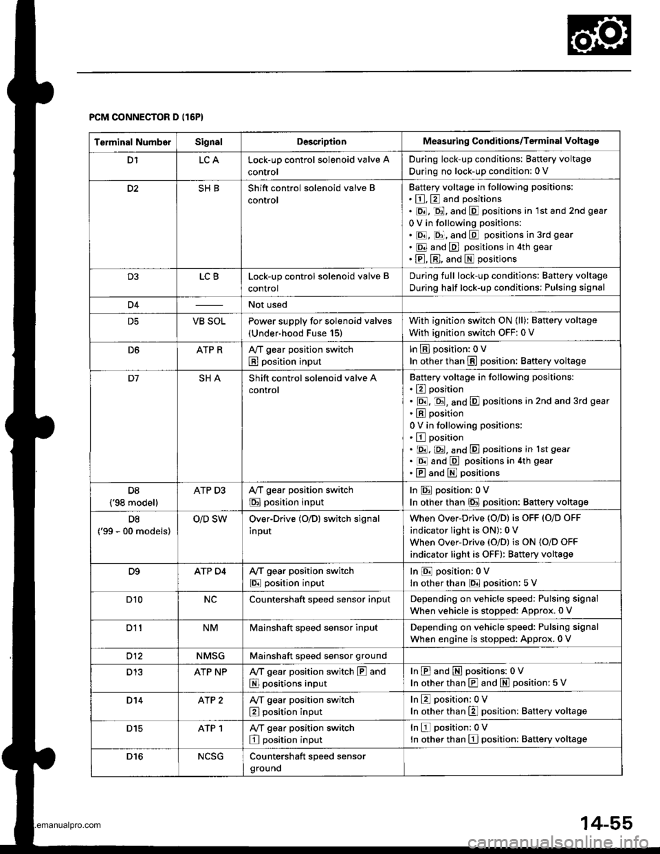
Terminal NumborSignalDescriptionMeasuring Conditions/Terminal Voltage
D1LCALock-up control solenoid valve A
control
During lock-up conditions: Baftery voltage
During no lock-up condition: 0 V
D2SHBShift control solenoid valve B
control
Battery voltage in following positions:
. E, E and positions
. E, -ql, and E positions in lst and 2nd gear
0 V in following positions:
. E, E;, and E positions in 3rd gear
. E and E positions in 4th gear
. E, El, and El positions
D3LCBLock-up control solenoid valve B
control
During full lock-up conditions: Battery voltage
During half lock-up conditions; Pulsing signal
D4Not used
D5VB SOLPower supply for solenoid valves
(Under-hood Fuse 15)
With ignition switch ON (ll); Battery voltage
With ignition switch OFF: 0 V
D6ATP RAy'T gear position switch
B position input
In E position: OV
In other than E position: Baftery voltage
D7SHAShift control solenoid valve A
control
Battery voltage in following positions:
. E position
. E, E, and E positions in 2nd and 3rd gear
. E position
0 V in following positions:
. E position. E. E, and E positions in lst gear
. Erl and E positions in 4th gear
.EandEpositions
D8
{'98 model}
ATP D3Ay'T gear position switch
E position input
In E position: 0V
In other than E position: Baftery voltage
D8
('99 - 00 models)
O/D SWOver-Drive (O/D) switch signal
input
When Over-Drive {O/D) is OFF (O/D OFF
indicator light is ON): 0 V
When Over-Drive {O/D) is ON {O/D OFF
indicator light is oFF): Battery voltage
D9ATP D4A/f gear position switch
E position input
In E position: 0V
In other than E position: 5 V
D10NCCountershaft sDeed sensor inoutDepending on vehicle speed: Pulsing signal
when vehicle is stopped: Approx.0 V
Dl1NMMainshaft speed sensor inputDepending on vehicle speed: Pulsing signal
When engine is stopped: Approx. 0 V
D12NMSGMainshaft speed sensor ground
D13ATP NPA,/T gear position switch E and
El positions input
InEandEpositions: 0V
In other than E and m position: 5 V
D14AlP 2A/T gear position switch
El position input
InE position; 0V
In other than E position: Battery voltage
D15ATP 1A,/T gear position switch
E position input
InEposition:0V
ln other than El position: Battery voltage
D16NCSGCountershaft speed sensor
grouno
PCM CONNECTOR D (16P)
14-55
www.emanualpro.com
Page 572 of 1395
Troubleshooting Procedures
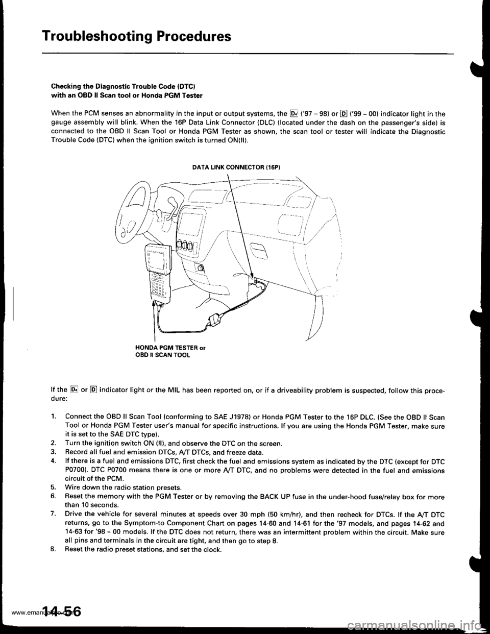
Checking ths Diagnostic Trouble Code (DTC)
with an O8D ll Scan tool or Honda PGM Tsster
When the PCM senses an abnormality in the input or output systems, the El ('97 - 98) or E ('99 - O0) indicator light in thegauge ass€mbly will blink. When the 16P Data Link Connector (DLC) {located under the dash on the passenger's side) is
connected to the OBD ll Scan Tool or Honda PGM Tester as shown, the scan tool or tester will indicate the Diagnostic
Trouble Code (DTC) when the ignition switch is turned ON(ll).
HONDA PGM TESTER olOBD II SCAN TOOL
lf the E or E indicator light or the MIL has been reported on, or if a driveability problem is suspected, follow this proce-
dure:
1. Connect the OBD ll Scan Tool (conforming to SAE J1978) or Honda PGM Tester to the 16P DLC. (See the OBD ll ScanTool or Honda PGM Tester user's manual for specific instructions. lf you are using the Honda PGM Tester, make sureit is set to the SAE DTC Wpe).2. Turn the ignition switch ON (ll), and observe the DTC on the screen
3. Record allfuel and emission DTCS, A,,/T DTCS, and freeze data.
4. lf there is a fuel and emissions DTC, first check the fuel and emissions system as indicated by the DTC (except for DTCP0700). DTC P0700 means there is one or more Ay'T DTC, and no Droblems were detected in the fuel and emissionscircuit of the PCM.
5. Wire down the radio station presets.
6. Reset the memory with the PGM Tester o. by removing the BACK UP fuse in the under-hood fuse/relay box for morethan 10 seconds.
7. Drive the vehicle for several minutes at speeds over 30 mph (50 km/hr), and then recheck for DTCS. lf the A/T DTCreturns, 9o to the Symptom-to Component Chart on pages 14-60 and 14-61 for the '97 models, and pages 14-62 and14-63 for '98 - 00 models. lf the OTC does not return, there was an intermittent problem within the circuit. Make sureall pins and terminals in the circuit are tight, and then go to step 8.8. Reset the radio Dreset stations, and set the clock.
DATA LINK CONNECTOR {16PI
[ -=.r,
ili,i /i,
v,., i
14-56
www.emanualpro.com
Page 575 of 1395
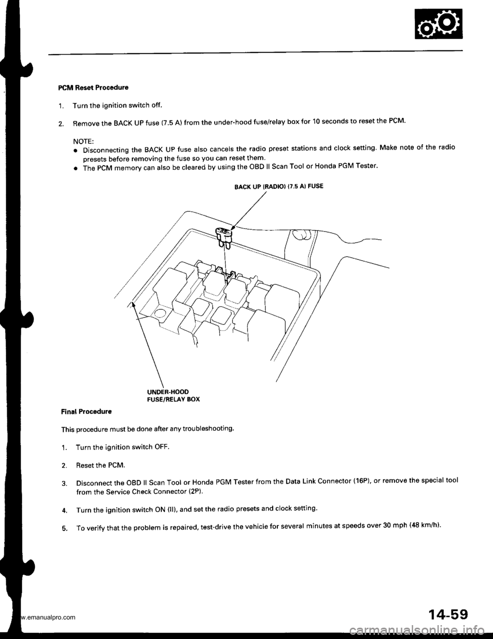
PCM Reset Procedure
'1. Turn the ignition switch off
2. Remove the BACK UP fuse (7.5 A) from the under-hood fuse/relay box for 10 seconds to reset the PCM.
NOTE:
. Disconnecting the BACK Up fuse also cancels the radio preset stations and clock setting Make note of the radio
presets before removing the fuse so you can reset them
. The PCM memorv can also be cleared by using the OBD ll Scan Tool or Honda PGM Tester'
UNDER.HOODFUSE/RELAY BOX
Final Proceduro
This procedure must be done after any troubleshooting.
1. Turn the ignition switch OFF.
2. Reset the PCM.
3. Disconnect the OBD ll Scan Tool or Honda PGM Tester from the Data Link Connector (16P), or remove the special tool
from the Service Check Connector (2P).
4. Turn the ignition switch ON (ll), and set the radio presets and clock setting'
5, To verify that the problem is repaired. test-drive the vehicle for several minutes at speeds over 30 mph (48 km/h).
BACK UP IRADIO} {7.5 AI FUSE
14-59
www.emanualpro.com