rod HONDA CR-V 1998 RD1-RD3 / 1.G Owner's Guide
[x] Cancel search | Manufacturer: HONDA, Model Year: 1998, Model line: CR-V, Model: HONDA CR-V 1998 RD1-RD3 / 1.GPages: 1395, PDF Size: 35.62 MB
Page 332 of 1395
PGM-FI System
Knock Sensor {KSl
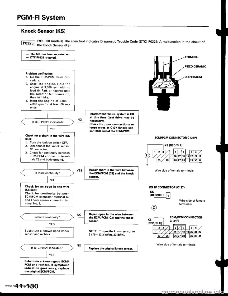
('99 - 00 models) The scan tool indicates Diagnostic Troublo Code (DTC) P0325: A malfunction in the circuit ofthe Knock Sensor (KS).
ECM/PCM CONNECTOR C 131P}
Wire side of female terminals
KS 1P CONNECTOR IC13?'
KSIRED/BLU)
KS(BED/BLU)
Wire side ol femaletermtnals
ECM/PCM CONNECTORc (31P)
- The MIL has been rooorted on.- DTC m325 is storod.
Problem verification:1. Do the ECM/PCir, Reset Procedure,2. Start the engine. Hold theengine at 3,000 rpm with noload (in Park or neutral) untilthe radiator tan comes on,then let it idle.3. Hold the engine at 3,000 -
4,000 rpm for at least 60 sec-onds,
Intermittent lailu.e, 3ystom is OKat thi3 tim. (te3t drive m.y benacalLrYr.Chock to. poor connsctions olloora wiros rt C137 lknock aon-.o. (KS)) and ar the ECM/FCM.
Ch€ck tor a short in the wir6 {KSlinel:1. Turn the ignition switch OFF.2, Disconnect the knock sensorlP connector.3. Check lor continuity betweenECM/PCM connector terminals C3 and body ground.
Replil rhort in the n irg b6{wocntho ECM/PCM lc:ll and the knocks€ngr1.
Check fo..n open in the wire{KS line):Check for continuity betweenECM/PCM connector terminal C3and knock sensor connector ter,minal No. 1.
B.pair opon in the wirc lrotweenlho ECM/PCM lctl and thc knockacnsor.
ls there cont;nuity?
Substitute a known-good knocksensor and recheck.
ls DTC P0325 indicated?Bcpl.ce the original knock 3€nsor,
Substituto a known-good ECM/PCM and .echeck. lf 3ymptom/indication goes away, replacethe original ECM/PCM.
NOTE: Torque the knock s6nsor to31 N.m (3.2 kgl.m, 23 lbf.ft).
1 1-130
Wire side ot female terminals
www.emanualpro.com
Page 338 of 1395
PGM-FI System
Vehicle Speed Sensor (VSSI {cont'd}
'98 - 00 models:
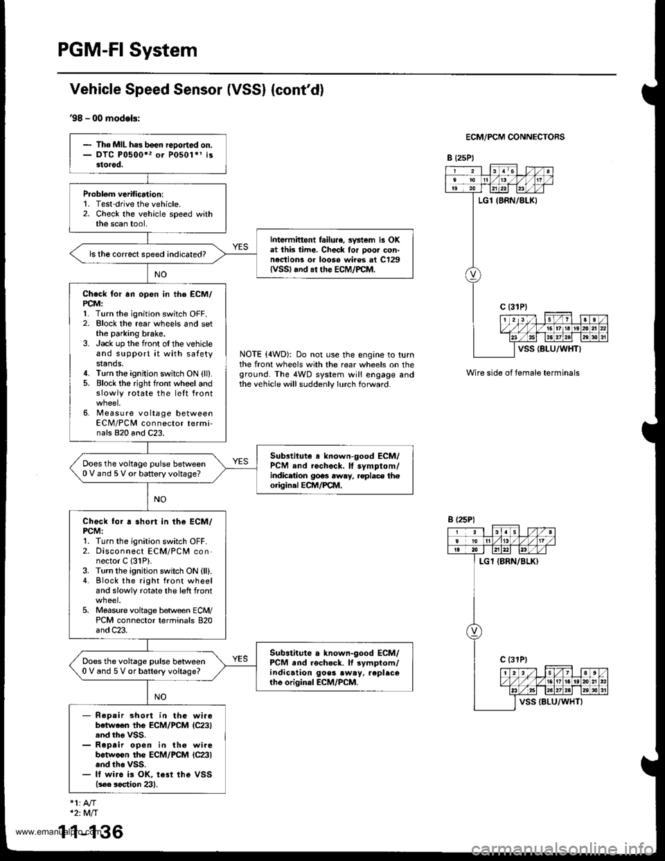
ECM/PCM CONNECTORS
B t25Pl
NOTE (4WD): Do not use the engine to turnthe front wheels with the rear wheels on theground. The 4WD system will engage andthe vehicle will suddenly lurch forward.
Wire side of female terminals
- The MIL ha3 been reDoned on.- DTC P0500" or P0501*1 i33torod.
Probl6m verification:1. Test-drive the vehicle.2. Check the vehicle speed withthe scan tool,
Intermittont failu.e, svstem is OKat thk time. Check for poor con-nection! or loose wiros at C129lvss) .nd ar the EcM/PcM.
ls the correct speed indicated?
Check for rn open in the ECM/PCM:l� Turn the ignition switch OFF.2. Elock the rear wheels and setthe parking brake.3. Jack up the front oI the vehicleand support it with satetystands.4. Turn the ignition switch ON {ll}.5. Block the right front whoel andslowly rotate the lett front
6. Measure voltage betweenECM/PCM connector termi-nals 820 and C23.
Substitute a known-good ECM/PCM and rochock. ll symptom/indicetion 9063 away, .oplace th€origin.l ECM/PCM.
Does the voltage pulse between0 V and 5 V or battery voltage?
Check for a short in the ECM/PCMI1. Turn the ignition switch OFF.2. Disconnect ECM/PCM connector C 131P).3. Turn the ignition swilch ON {ll).4. Block the right front wheeland slowly rotate the left front
5. Moasure voltage between ECM/PCM connector terminals 820and C23.
Sub.titute a known-good ECM/PCM and rschock. It rymptom/indication goos .w.y. replecerhe original ECM/PCM.
Does the voltage pulse betlveen0 V and 5 V or battery voltage?
- R.pair short in the wirobetwe€n the ECM/PCM lC23).nd tho VSS.- Roprir open in th6 wirebotweon the ECM/PCM lc23land th6 vss.- It wirc is OK, te3t ihe VSS(!€e soetion 23).
B (25P)
1
*2:Mft
1-136
www.emanualpro.com
Page 410 of 1395
Emission Control System
Evaporative Emission (EVAP) Controls (cont'd)
99 - 00 models:
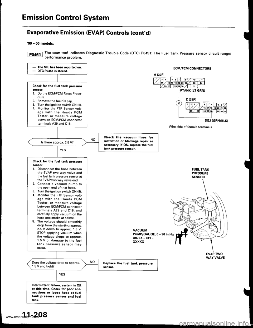
The scan tool indicates Diagnostic Trouble Code {DTC) P0451: The Fuel Tank Pressure sensor circuit range/oerformance Droblem.
ECM/PCM CONNECTORS
SG2 {GRN/BLK)
Wire side of {emaleterminals
FUEL TANKPRESSURESENSOR
VACUUMPUMP/GAUGE.0 -30 in.H9A973X - 041 -
XXXXX
- The MIL har been rooort€d on.- DTC P0451 b storod.
Check lor th6 tu6l tank pr€ssurelen30r:1. Do the ECM/PCM Reset Proce,oure.2. Remove the fuelfill cap.3. Turn the ignition switch ON (ll).4. Monitor the FTP Sensor voltage with the Honda PGMTester, or measure voltagebetween ECM/PCM connectorterminals A29 and C18.
Chock tho vacuum lin6s torrGlriction o. blockago repair asnecessary. lf OK, roplace the fueltank Drer3ur€ sentor.
ls there approx. 2.5 V?
Check for the fuel tank piessureSensot:L Disconnect the hose betweenthe EVAP two way valve andthe fuel tank pressure sensor atthe EVAP two way valve end.2. Connect a vacuum pump tothe open end ofthat hose.3. Turn the ignition switch ON (lll.4. Monitor the FTP S€nsor volt-age with the Honda PGMTester, or measure voltagebetween ECNI/PCNI connectorterminals A29 and C18, andcarefully appiy vacuum on thehose one stroke at a time.5. The voltage should smoothlydrop from the staning approx.2.5 V down to approx. 1.5 V.STOP applying vacuum whenthe voltage drops to approx.1.5 V or damage to the tueltank pressure sensor may
Does the voltage drop to approx.1.5 V and hold?
Intermittent tailuro. sv3tem is OKat this tim€. Chack to. poor con-n€ction6 or 10036 hose at fu6ltank pres3ure ionsor and fueltrnk.
a t32Pl
PTANK ILT GRNI
WAY VALVE
11-208
www.emanualpro.com
Page 421 of 1395
'98 - 00 mod€ls:
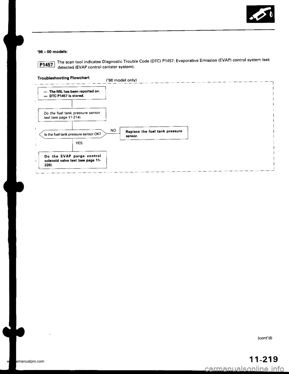
The scan tool indicates Diagnostic Trouble code (DTc) P1457: Evaporative Emission (EVAP) Control system leak
detected (EVAP control canister system).
Troubl6shooting Flowchart('98 model only)_]
I
- The MIL has been rePorted on.- DTC P1,157 is storod.
Do the fuel tank Pressure sensor
test {see page 11-214).
ls the {ueltank pressure sensor OK?
Do the EVAP Purge contlol
solenoid valve test lsea Page 1l_
220t.
(cont'dl
11-219
www.emanualpro.com
Page 431 of 1395
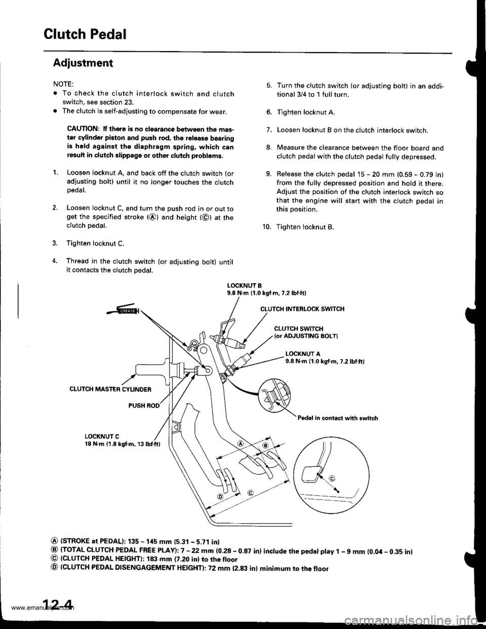
Clutch Pedal
Adiustment
NOTE:
. To check the clutch interlock switch and clutch
switch, see section 23.
. The clutch is self-adjusting to compensate for wear.
CAUTION: lf there is no clearance bstwa€n the mas-
ter cylinder piston and push rod, ths roloase bearingis held againsi the diaphragm spring, which canresuh in clutch slippage or other clutch probloms.
1. Loosen locknut A, and back off the clutch switch (or
sdjusting bolt) until it no longer touches the clutchpeoar.
2. Loosen locknut C, and turn the push rod in or out toget the specified stroke (@) and height (@) at theclutch oedal.
3. Tighten locknut C.
4. Thread in the clutch swirch (or adjusting bolt) untilit contacts the clutch oedal.
7.
5.
8.
q
Turn the clutch switch {or adjusting bolt} in an addi-
tional 3/4 to 1 full turn.
Tighten locknut A.
Loosen locknut B on the clutch interlock switch.
Measure the clearance between the floor board and
clutch pedalwith the clutch pedal fully depressed.
Release the clutch pedal 15 - 20 mm (0.59 - 0.79 in)
from the fully depressed position and hold it there,Adjust the position of the clutch interlock switch sothat the engine will start with the clutch pedal in
this position.
Tighten locknut B.10.
LOCKNUT B9.8 N.m 11.0 kgf.m, 7.2 lbf.ftl
CLUTCH INTERLOCK SWITCH
CLUTCH SWTTCH{or ADJUSTING BOLTI
L(rcKNUT A9.8 N.m {1.0 kg{.m,7.2 lbf.ftl
CLUTCH MASTER CYLINDER
PUSH ROD
Pedal in contact with swhch
LOCKNUT C18 N.m (1.8 kgf.m, 13lbtftl
@ {STROKE at PEDAL): 135 - 1its mm (5.31 - 5.71 in}
@ (TOTAL CLUTCH PEDAL FREE PLAY)i7 -22mm (0.28-0.87 in) inctude the pedat ptay 1 - 9 mm (0.0it- 0.35 inl@ (GLUTC,H PEDAL HE|GHTI: ltxt mm (7.20 inl ro rhe ftoor
o (CLUTCH PEDAL DTSENGAGEMENT HEtcHTl: 72 mm {2.txt inl minimum to the floor
\,/a_-_--/
12-4
www.emanualpro.com
Page 443 of 1395
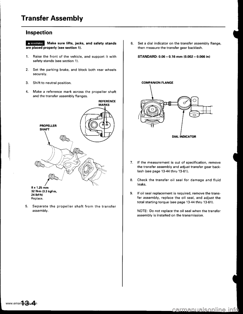
Transfer Assembly
lnspection
@ Make sure tifts, iacks, and satety stands
are placed properly (see section 1).
L Raise the front of the vehicle, and support it with
safety stands (see section 1).
2. Set the parking brake, and block both rear wheels
securely.
3. Shift to neutral oosition.
4. Make a reference mark across the DroDeller shaft
and the transfer assembly flanges,
REFERENCE
8 x 1.25 mm32 N.m (3.3 kg{.m.24 rbf.ftlReplace.
Separate the propeller shaft from the transfer
assemDty.
5.
13-4
6. Set a dial indicator on the transfer assembly flange,
then measure the transfer gear backlash.
STANDARD: 0.06 - 0.16 mm (0.002 - 0.006 in)
COMPAf{ION FI-ANGE
1.lf the measurement is out of specification, remove
the transfer assembly and adjust transfer gear back-
lash (see page 13-44 thru '13-61).
Check the transfer oil seal for damage and fluid
teaKs.
lf oil seal replacement is required, remove the trans-
fer assembly, replace the oil seal, and adjust the
total starting torque (see page 13-44 thru 13-61).
NOTE: Do not replace the oil seal when the transfer
assembly is installed on the transmission.
www.emanualpro.com
Page 515 of 1395
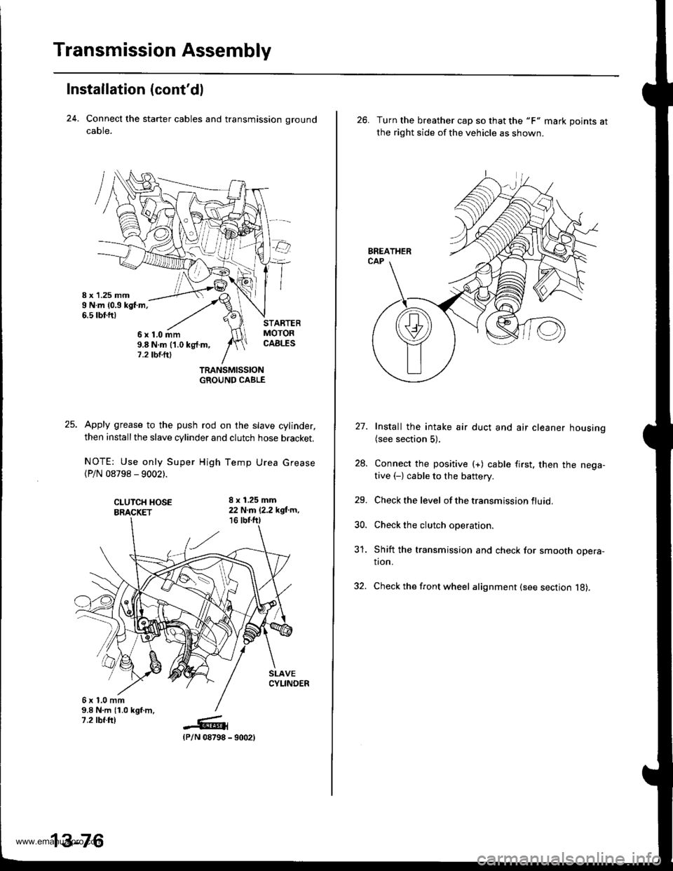
Transmission Assembly
Installation (cont'dl
24. Connect the starter cables and transmission ground
caore.
TRANSMISSIONGROUND CABLE
Apply grease to the push rod on the slave cylinder,
then install the slave cylinder and clutch hose bracket,
NOTE: Use only Super High Temp Urea Grease
{P/N 08798 - 9002).
CI-UTCH HOSEBRACKET
8 x 1.25 mm22 N.m 12.2 kgi-m,16 tbr.f0
6x1.0mm9.8 N.m {1.0 kgf.m,7.2 rbf.ftt_G1(P/N 08798
6x1.0mm9.8 N.m (1.0 kg{.m,7.2 tbt.ttl
13-76
- 9002)
26. Turn the breather cap so that the "F" mark points at
the right side of the vehicle as shown.
27. Install the intake air duct and air cleaner housing(see section 5),
28. Connect the positive (+) cable first. then the nega-
tive (-) cable to the battery.
29. Check the level of the transm ission f lu id.
30. Check the clutch operation.
31. Shift the transmission and check for smooth opera-tion.
32. Check the front wheel alignment (see section l8).
www.emanualpro.com
Page 520 of 1395
Description
General Operation (cont'dl
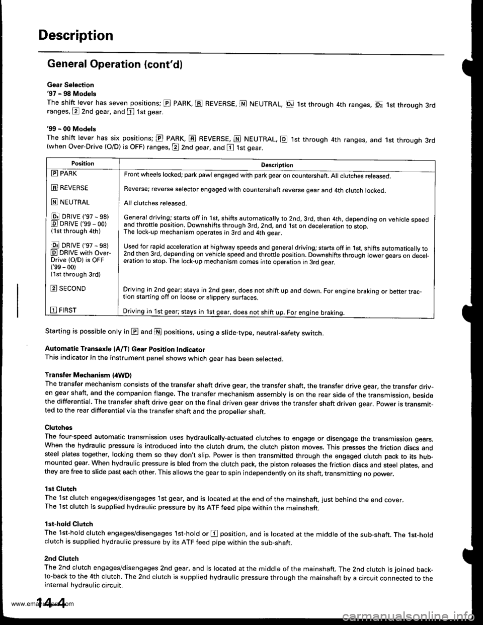
Gsar Selection'97 - 98 Models
The shift lever has seven positions; El PARK, ts REVERSE, N NEUTRAL, Ell 1st through 4th ranges, lpq 1st th.ough 3rdranges, P 2nd gear, and [ 1st gear
'99 - 00 Models
The shitt lever has six positions; El PARK, E REVERSE, E NEUTRAL. E ,lst through 4th ranges, and 1st through 3rd(when Over-Drive (O/D) is OFF) ranges. @ 2nd gear, and E 1st gear.
Starting is possible only in @ and @ positions. using a slide-type. neutral-safety switch.
Automatic Transaxle (A/T) Gear Position IndicatorThis indicator in the instrument panel shows which gear has been selected.
Transler Mochanism {4WD}
The transfer mechanism consists of the transfer shaft drive gear. the transfer shaft. the transfer drive gear, the transfer driv-en gear shaft, and the companion flange, The transfer mechanism assembly is on the rear side ot the transmission. besidethe differential. The transfer shaft drive gear on the final driven gear drives the transfer shaft driven qear. power is transmit-ted to the rear differential via the transfer shaft and the Drooeller shaft.
Clutches
The four-speed automatic transmission uses hydraulically-actuated clutches to engage or disengage the transmission gears.When the hydraulic pressure is introduced into the clutch drum, the clutch piston moves. This presses the friction discs andsteel plates together, locking them so they don't slip. Power is then transmifted through the engaged clutch pack to its hu$mounted gear. When hydraulic pressure is bled from the clutch pack, the piston releases the friction discs and steel plates, andthey are free to slide past each other. This allows the gearto spin independently on its shaft, transmitting no power.
lst Clutch
The 1st clutch engages/disengages lst gear, and is located at the end ofthe mainshaft, just behind the end cover.The 1st clutch is supplied hydraulic pressure by its ATF feed pipe within the mainshaft.
lst-hold Clutch
The 1st-hold clutch engages/disengages 1st-hold or E position, and is located at the middle of the sub-shaft. The 1st-holdclutch is supplied hydraulic pressure by its ATF feed pipe within the sub-shaft.
2nd Clutch
The znd ciutch engages/disengages 2nd gear, and is located at the middle of the mainshaft. The 2nd clutch is joined back-to-back to the 4th clutch. The 2nd clutch is supplied hydraulic pressure through the mainshaft by a circuit connected to theinternal hydraulic circuit.
PositionDescription
Reverse; reverse selector engaged with countershaft reverse gear and 4th clutch locked.
Allclutches released.
General driving; starts off in 1st, shifts automatically to 2nd, 3rd, then 4th, depending on vehicle speedand throftle position. Downshifts through 3rd,2nd, and lst on deceleration to stop.The lock-up mechanism operates;n 3rd and 4th gear.
used for rapid €cceleration at highway speeds and general driving; stans off in 1st, shifts automatically to2nd_then 3rd, dejending on vehicle speed and throttle position. Downshifts through lower gears on decel-eration to stop. The lock-up mechanism comes into operation in 3rd gear.
Driving in 2nd_gear; stays in 2nd gear, does not shift up and down. For engine braking or better trac_tion starting off on loose or slippery surfaces.
Driving in 1st gear; stays in 1st gear, does not shift up. For engine braking.
tll PARK
t!!l l|EvEn>E
E NEUTRAL
Ell DRrvE ('97 - sB)E DRrvE ('ss - oo)(1st through 4th )
E DRrvE {'97 - s8)O DRTVE with over-Drive (O/D) is OFF('99 - 00)(1st through 3rd)
E SECOND
E FIRST
14-4
www.emanualpro.com
Page 564 of 1395
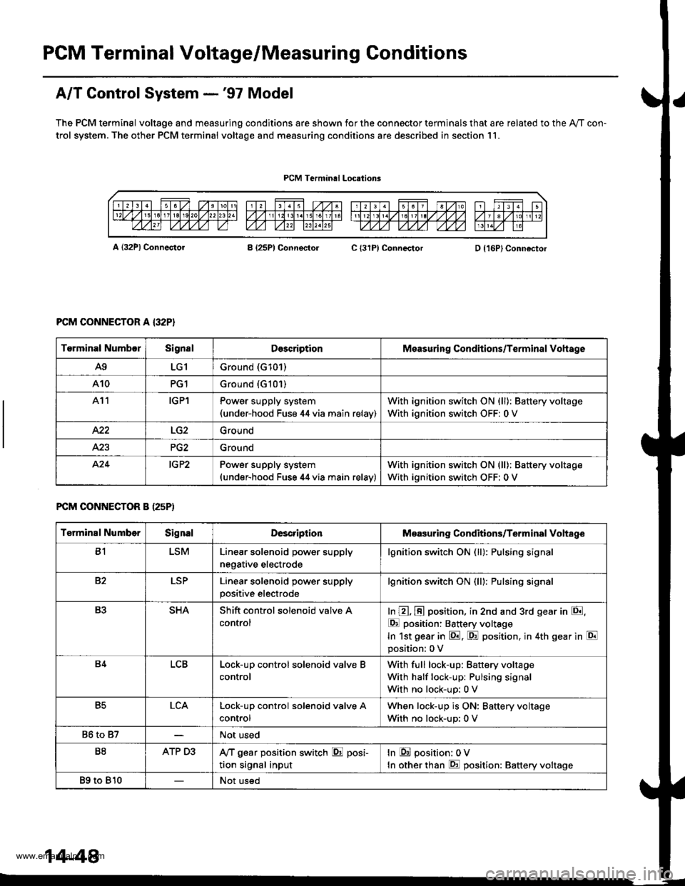
PGM Terminal Voltage/Measuring Conditions
A/T Control System -'97 Model
The PCM terminal voltage and measuring conditions are shown for the connector terminals that are related to the Ay'T con-
trol system. The other PCM terminal voltage and measuring conditions are described in section 11.
PCM Terminal Locations
A {32P} ConnectorB (25P1 ConnectolC {31PI ConnectorD {16P}Connector
PCM CONNECTOR A {32P}
FCM CONNECTOR B (25P)
Torminal NumbcrSignslDescriptionMeasuring Conditions/Terminal Vohage
A9LG1Ground (G101)
A10PG1Ground {G101)
At1IGPlPower supply system(under-hood Fuse 44 via main relav)
With ignition switch ON (ll): Battery voltage
With ignition switch OFF: 0 V
422Ground
Ground
424IG P2Power supply system(under-hood Fuse 44 via main relav)
With ignition switch ON (ll): Battery voltage
With ignition switch OFF: 0 V
Terminal NumberSignalDescriptionMeasuring Conditions/Terminal Vohage
B1LSMLinear solenoid power supply
negative electrode
lgnition switch ON (ll): Pulsing signa
82LSPLinear solenoid power supply
positive electrode
lgnition switch ON (lll: Pulsing signa
B3SHAShift control solenoid valve A
control
In @, @ position, in 2nd and 3rd gear in E,
E position: Battery voltage
In 1st gear in E. F! position, in 4th gear in E
position: 0 V
B4LCBLock-up control solenoid valve B
control
With full lock-up: Battery voltage
With half lock-up: Pulsing signal
With no lock-up: 0 V
B5LCALock-up control solenoid valve A
control
When lock-up is ON: Baftery voltage
With no lock-up: 0 V
86 to 87Not used
B8ATP D3,VT gear position switch E posi-
tion signal input
In E position: 0V
In other than E position: Battery voltage
89 to 810Not used
14-48
www.emanualpro.com
Page 570 of 1395

PCM Terminal Voltage/Measuring Conditions
A/T Control System -'98 - 00 Models
The PCM terminal voltage and measuring conditions are shown for the connector terminals that are related to the A"/T con-
trol system. The other PCM terminal voltage and measuring conditions are described in section 11.
FCM Connector Terminal Localions
NOTE: 819 and C3 terminalsare applied to'99 - 00 models.
o (16Pt
T6rminal NumberSignalDescriptionMeasuring Conditions/Terminal Voltage
A5CRSDownshift signal input from
cruise control unit
When cruise control is used; Pulsing signal
A10scsTiming and adjustment service
check signal (5 V from PCM)
With ignition switch ON (ll) and service check
connector open:5 V
With ignition switch ON (ll) and service check
connector jumped with special tool: 0 V
A14('98 model)
D4 INDD4 indicator light control
{Voltage from PCM turns D4 light
oN)
When ignition switch is first turned ON (ll):
Battery voltage for two seconds
In E position: Battery voltage
A14
('99 - 00 models)
D INDD indicator light control(Voltage from PCM turns D light
oN)
When ignition switch is first turned ON (ll):
Baftery voltage for two seconds
ln E position: Battery voltage
428ILUInterlock control(Voltage from PCM)
When ignition switch ON {ll), brake pedal
depressed, and accelerator pedal released:
Battery voltage
A.32STOP SWBrake switch signal inputBrake pedal pressed; Battery voltage
Brake pedal released: 0 V
FCM CONNECTOR B I25P}
Terminal NumberSignalDescriptionMeasuring Conditions/Terminal Voltage
B1IGPlPower supply circuit from main
relay via under-hood Fuse 44
With ignition switch ON {ll): Battery voltage
With ignition switch OFF: 0 V
82PG1Ground (G101)
B8LSMLinear solenoid power supply
negative electrode
IG P2Power supply circuit from main
relay
With ignition switch ON (ll): Baftery voltage
With ignition switch OFF: 0 V
810PG2Ground (G101)
B17Linear solenoid power supply
positive electrode
With ignition switch ON (ll): Pulsing signal
819
('99 - 00 models)
O/D INDOver-Drive (O/D) OFF indicator
light control
When ignition switch is first turned ON (ll):
0 V for two seconds
O/D OFF indicator light ON:0 V
O/D OFF indicator light OFF: Battery voltage
s20Ground (G101)
B�21VBUBack-up power supply(under-hood Fuse 47)
Always battery voltage
B�22LG2Ground (G101)
14-54
www.emanualpro.com