check oil HONDA CR-V 1998 RD1-RD3 / 1.G Repair Manual
[x] Cancel search | Manufacturer: HONDA, Model Year: 1998, Model line: CR-V, Model: HONDA CR-V 1998 RD1-RD3 / 1.GPages: 1395, PDF Size: 35.62 MB
Page 713 of 1395
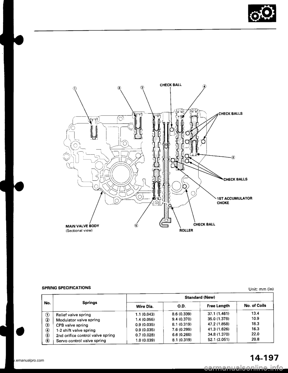
CHECK BALL
i)L)
lo
CHECK BALLS
lST ACCUMULATORCHOKE
CHECK EALLMAIN VALVE BODY(Sectionalview)
SPRING SPECIFICATIONSUnit: mm (in)
No.Springs
Standard {New)
Wire Dia.o.D.Froe LengthNo. of Coils
o
@
@
@
Relief valve spring
Modulator valve spring
CPB valve spring
1-2 shift valve spring
2nd orifice control valve spring
Servo control valve sPring
1.1 (0.043)
1.4 (0.055)
0.9 (0.03s)
0.9 (0.035)
0.7 (0.028)
1.0 t0.039)
8.6 (0.339)
9.4 (0.370)
8.1 (0.319)
7.6 (0.299)
6.6 (0.260)
8.1 {0.319)
37.1 (1.461)
35.0 (1.3781
41 .2 \1 .8581
41.3 (1.626)
34.8 (1.370)
52.1 (2.051)
'13.4
10.9
20.8
14-197
www.emanualpro.com
Page 714 of 1395
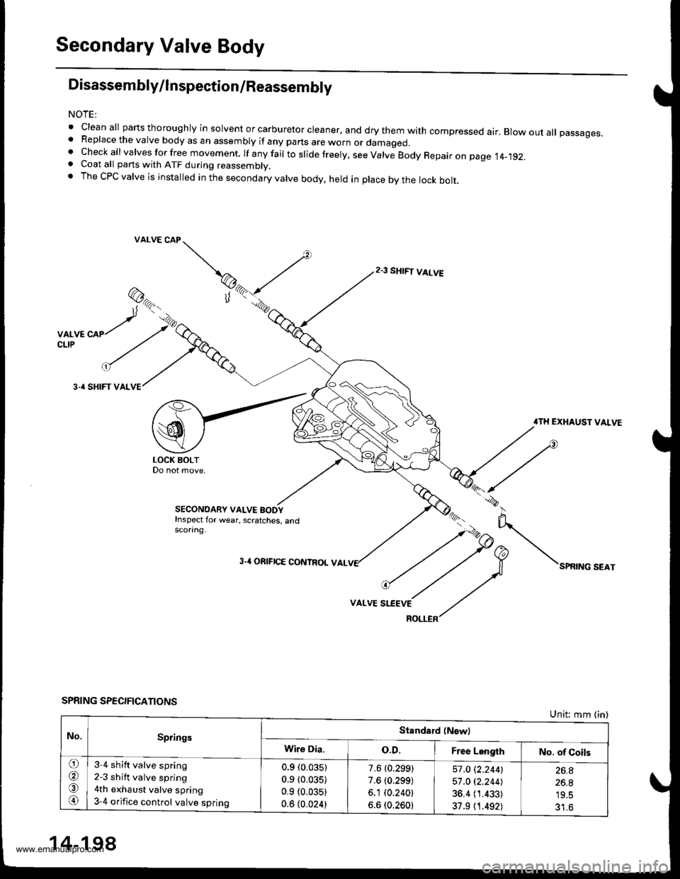
Secondary Valve Body
Disassembly/lnspection/Reassembly
NOTE:
' clean all parts thoroughly in solvent or carburetor cleaner. and dry them with compressed air. Blow out aU passages,. Replace the valve body as an assembly if any parts are worn or damaged.t check all valves for free movement. rf anyfair to sride freery. see varve Body Repair on page 14-192.. Coat all parts with ATF during reassembly.. The CPC valve is installed in the secondary valve body, held in place by the lock bolt.
@,.-.t'tr.,
,rr'^'//u
"/ ./
3-' SHIFT VALVE
VALVE CAP
SPRING SPEC!FICATIONS
2.3 SHIFT VALVE
VALVE SLEEVE
ROLLER
ilTH EXHAUST VALVE
N"*,"o"*,
Unit: mm (in)
t*-1
SECONOARY VALVE BODYInspect for wear, scratches, andscorang.
3.4 ORIFICE CONTROL VAL
No.SpringsStandald {Nswl
Wire Dia.o.D.Free LengthNo. of Coils
o
@
o
@
3 4 shift valve spring
2-3 shift valve spring
4th exhaust valve spring
3-4 orifice control valve spring
0.9 (0.035)
0.9 (0.035)
0.9 {0.035)
0.6 {0.024}
7.6 (0.299)
7.6 (0.299)
6.1 (0.240t
6.6 (0.2601
57 .O i.2.2441
57 .O 12.244J
36.4 (1.433)
37.9 (1.492)
26.A
26.8
19.5
31.6
14-198
www.emanualpro.com
Page 715 of 1395
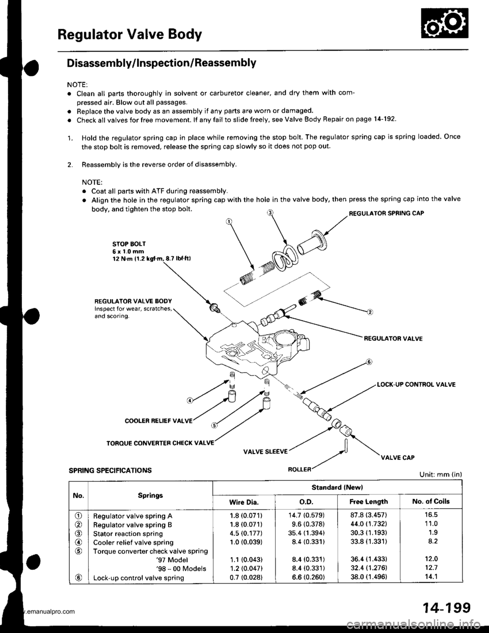
Regulator Valve Body
Disassembly/lnspection/Reassembly
NOTE:
o Clean all parts thoroughly in solvent or carburetor cleaner, and dry them with com-
pressed air. Blow out all passages.
. Replace the valve body as an assembly if any parts are worn or damaged.
. Checkall valvesforfree movement. lf anyfail toslidefreely, see Valve Body Repair on page l4-192.
'1. Hold the regulator spring cap in place while removing the stop bolt. The regulator spring cap is spring loaded Once
the stop bolt is removed, release the spring cap slowly so it does not pop out.
2. Reassembly is the reverse order of disassembly.
NOTE:
. Coat all parts with ATF during reassembly.
. Align the hole in the regulator spring cap with the hole in the valve body, thenpress the spring cap into the valve
REGULATOR SPSING CAPbody, and tighten the stop bolt.
STOP BOLT6x1.0mm12 N.m 11.28.? tbt.fil
REGULATOR VALVE BODYlnspect for wear, scratches,ano scoflng.
REGULATOR VALVE
No,SpringsStandard {New}
wire Dia.o.D.F ee LengthNo. ot Coils
o
@
@,6
a,
Regulator valve spring A
Regulator valve spring B
Stator reaction spring
Cooler relief valve spring
Torque converter check valve spring'97 Model'98 - 00 Models
Lock-up control valve spring
1.8 (0.071)
1.8 (0.071)
4.5 (0.177)
1.0 {0.039)
1.1 (0.043)
1.2lO.O47l
0.7 t0.028)
14.7 (0.579)
9.6 (0.378)
35.4 (1.394)
8.4 {0.331)
8.4 (0.331)
8.4 (0.331)
6.6 (0.260)
87.8 (3.457)
44.0 t1.7321
30.3 (1.193)
33.8 (1.331)
36.4 (1.433)
32.4 11.2761
38.0 (1.496)
'11.0
1.9
't2.0
12.7
14.'l
14-199
www.emanualpro.com
Page 717 of 1395
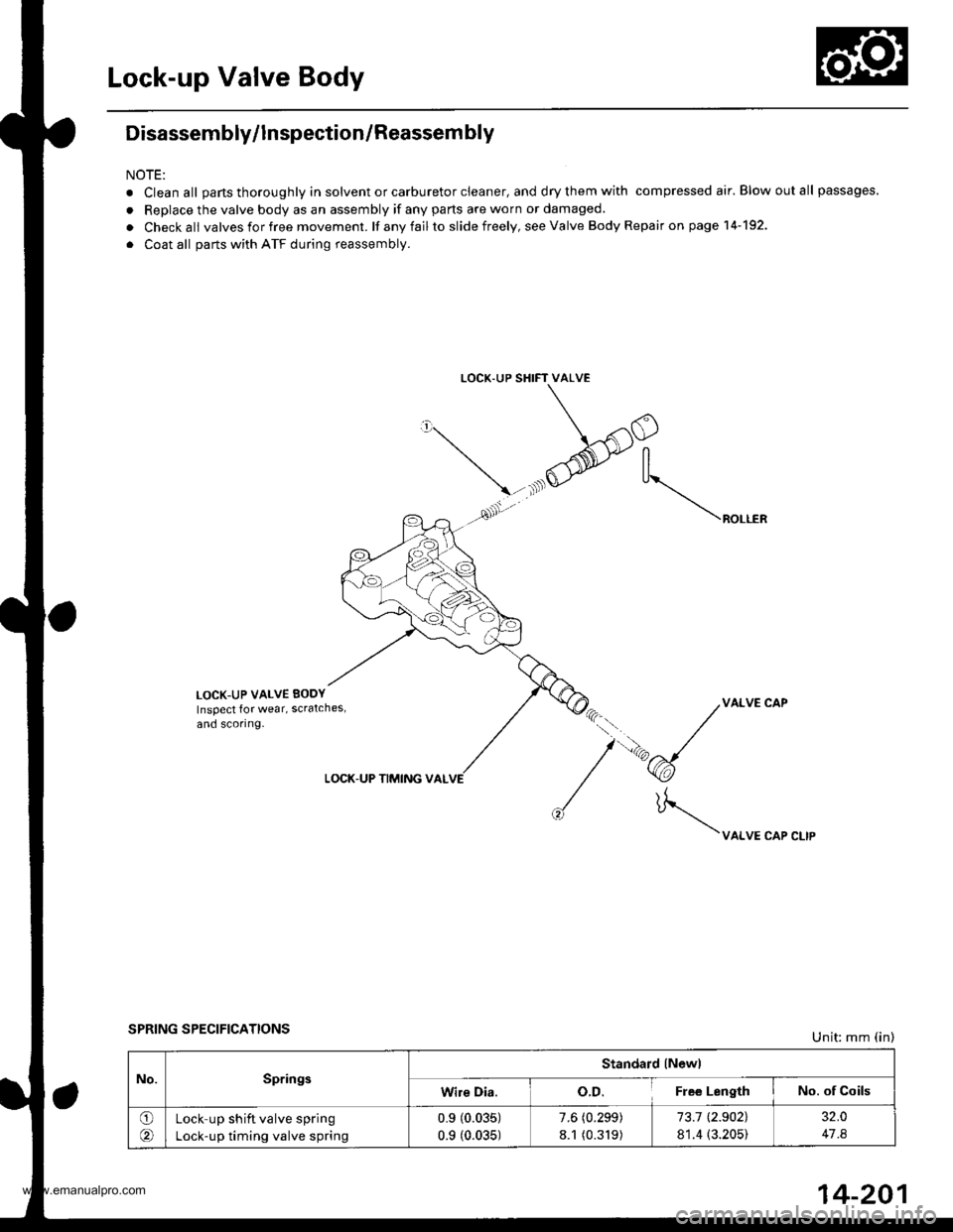
Lock-up Valve Body
Disassembly/lnspection/Reassem bly
NOTE:
. Clean all parts thoroughly in solvent or carburetor cleaner, and dry them with compressed air. Blow out all passages.
. Replace the valve body as an assembly if any parts are worn or damaged.
. Checkall valvesforfree movement. lf anyfailto slide freely, seeValve Body Repairon page 14-192.
. Coat all parts with ATF during reassembly.
LOCK.UP SHIFT VALVE
\/'
\-.xlO
@-tr
, ^ ,As'. \"o...*
LOCK-UP VALVE EODY
Inspect lor wear, scratches,
and scoring.
VALVE CAP
\uo.*"or".,,
LOCK-UP TIMING VAL
SPRING SPECIFICATIONSUnit: mm (in)
No.SpringsStandard lNewl
Wire Dia.o.D.Fle€ LengthNo. of Coils
O(Lock up shift valve spring
Lock-up timing valve spring
0.9 (0.035)
0.9 (0.035)
7.6 (0.299)
8.1 (0.319)
73.1 t2.902),
81.4 (3.205)
32.0
47 .8
14-201
www.emanualpro.com
Page 796 of 1395
Description
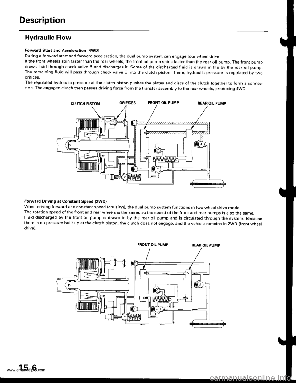
Hydraulic Flow
Forward Start and Acceleration l4WD)During a forward start and forward acceleration, the dual pump system can engage four wheel drive.lf the front wheels spin faster than the rear wheels, the front oil pump spins faster than the rear oil pump. The front pump
draws fluid through check valve B and discharges it. Some of the discharged fluid is drawn in the by the rear oil pump.The remaining fluid will pass through check valve E into the clutch piston. There, hydraulic pressure is regulated by twoorifices.
The regulated hydraulic pressure at the clutch piston pushes the plates and discs of the clutch together to form a connec-tion. The engaged clutch then passes driving force from the transfer assembly to the rear wheels, producing 4WD.
oRrFtcEsFRONT OIL PUMPREAR OIL PUMP
Forward Driving at Constant Speed lzWD)When driving forward at a constant speed (cruising), the dual pump system functions in two wheel drive mode.The rotation speed of the front and rear wheels is the same, so the speed of the front and rear pumps is also the same.Fluid discharged by the front oil pump is drawn in by the rear oil pump and is circulated through the system. Becausethere is no pressure built up at the clutch piston, the clutch does not engage, and the vehicle remains in 2WD (front wheeldrive).
FRONT OIL PUMP
15-6
www.emanualpro.com
Page 797 of 1395
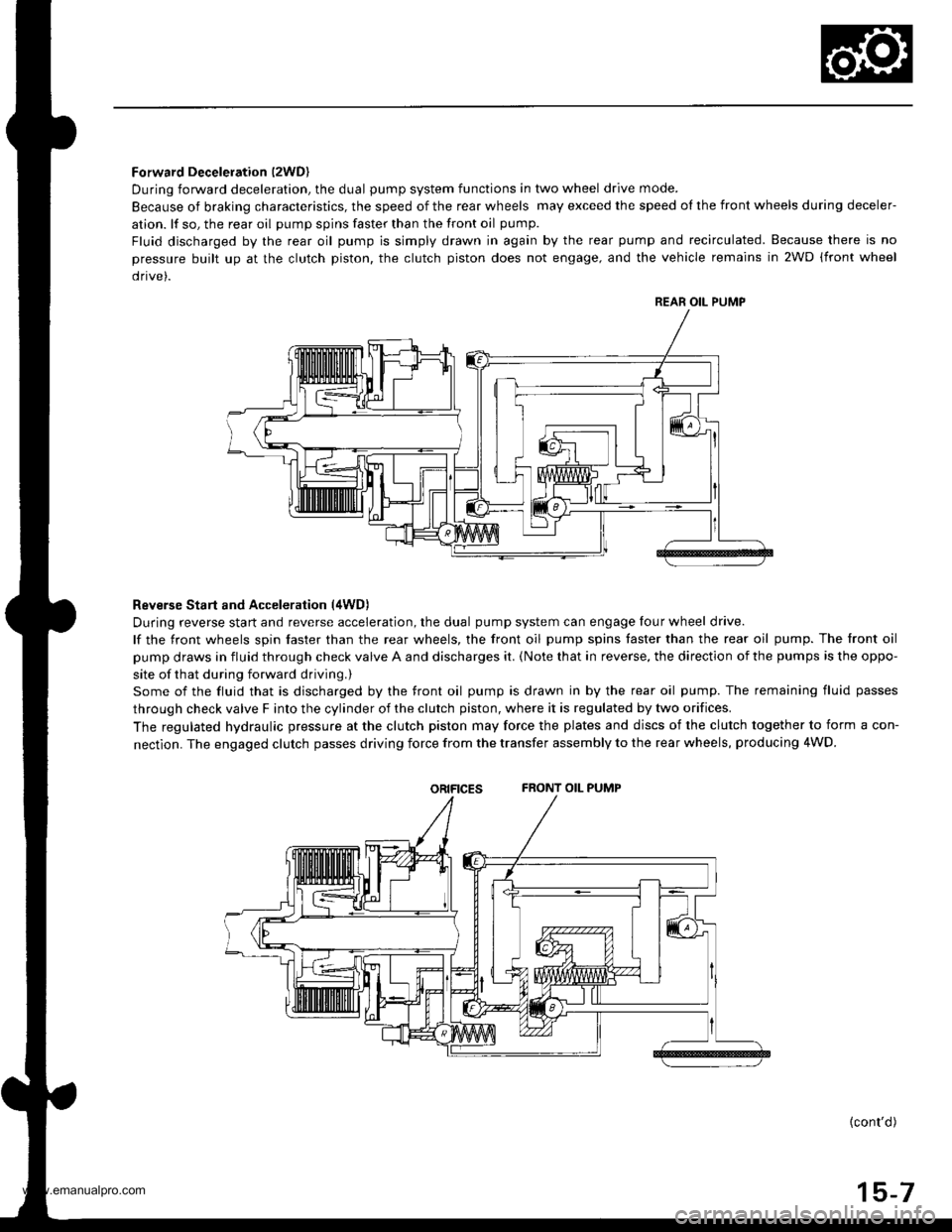
Forward Deceleration l2WDl
During forward deceleration, the dual pump system functions in two wheel drive mode.
Because of braking characteristics, the speed of the rear wheels may exceed the speed ol the front wheels during deceler-
ation. lf so, the rear oil pump spins faster than the front oil pump.
Fluid discharged by the rear oil pump is simply drawn in again by the rear pump and recirculated. Because there is no
pressure built up at the clutch piston. the clutch piston does not engage, and the vehicle remains in 2WD (front wheel
drive).
Reverse Start and Acceleration (4WD)
During reverse start and reverse acceleration, the dual pump system can engage four wheel drive.
lf the front wheels spin faster than the rear wheels, the front oil pump spins faster than the rear oil pump. The front oil
pump draws in fluid through check valve A and discharges it. {Note that in reverse, the direction of the pumps is the oppo-
site of that during forward driving.)
Some of the fluid that is discharged by the front oil pump is drawn in by the rear oil pump. The remaining fluid passes
through check valve F into the cylinder of the clutch piston, where it is regulated by two orifices.
The regulated hydraulic pressure at the clutch piston may force the plates and discs of the clutch together to form a con-
nectlon. The engaged clutch passes driving force from the transfer assembly to the rear wheels, producing 4WD.
oRtFtcEsFRONT OIL PUMP
{cont'd)
15-7
REAR OIL PUMP
www.emanualpro.com
Page 798 of 1395
Description
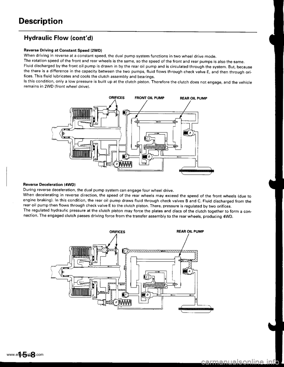
Hydraulic Flow (cont'dl
Reverse Driving at Constant Speed l2WD)when driving in reverse at a constant speed, the dual pump system functions in two wheel drive mode.The rotation speed of the front and rear wheels is the same, so the speed of the front and rear pumps is also the same,Fluid discharged by the front oil pump is drawn in by the rear oil pump and is circulated through the system. But, becausethe there is a difference in the capacity between the two pumps, fluid flows through check valve E, and then through ori-Iices. This fluid lubricates and cools the clutch assembly and bearings.ls this condition, only a low pressure is built up at the clutch piston. Therefore the clutch does not engage, and the vehicleremains in 2WD (front wheel drive).
Reverse Deceleration l/tWDl
During reverse deceleration, the dual pump system can engage four wheel drive.When decelerating in reverse direction, the speed of the rear wheels may exceed the speed of the front wheels (due toengine braking). In this condition, the rear oil pump draws fluid through check valves B and C. Fluid discharged from therear oil pump then flows through check valve E to the clutch piston. There, pressure is regulated by two orifices.The regulated hydraulic pressure at the clutch piston may force the plates and discs of the clutch together to form a con,nection. The engaged clutch passes driving force from the transfer assembly to the rear wheels, producing 4WD.
oRtFtcEsREAR OIL PUMP
www.emanualpro.com
Page 803 of 1395
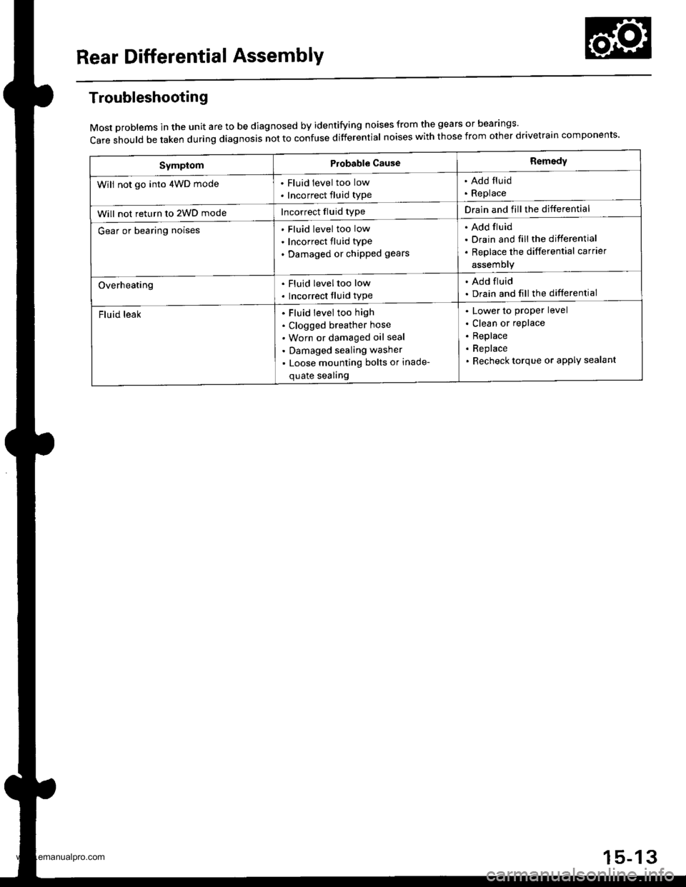
Rear Differential AssemblY
Troubleshooting
Most problems in the unit are to be diagnosed by identifying noises from the gears or bear'ngs'
care should be taken during diagnosis not to confuse differential noises with those from other drivetra'n components'
SymptomProbable CauseRemedy
Will not go into 4WD mode. Fluid level too low
. Incorrect fluid type
. Add fluid. Replace
Will not return to 2WD modeIncorrect fluid typeDrain and fill the differential
Gear or bearing noisesFluid level too low
Incorrect fluid type
Damaged or chipped gears
Add fluid
Drain and fill the differential
Replace the differential carrier
assemory
Overheating. Fluid leveltoo low
. Incorrect fluid type
. Add fluid. Drain and fill the differential
Fluid leakFluid level too high
Clogged breather hose
Worn or damaged oil seal
Damaged sealing washer
Loose mounting bolts or inade-
quate sealing
Lower to proper level
Clean or replace
Replace
Replace
Recheck torque or aPPIY sealant
15-13
www.emanualpro.com
Page 804 of 1395
Maintenance
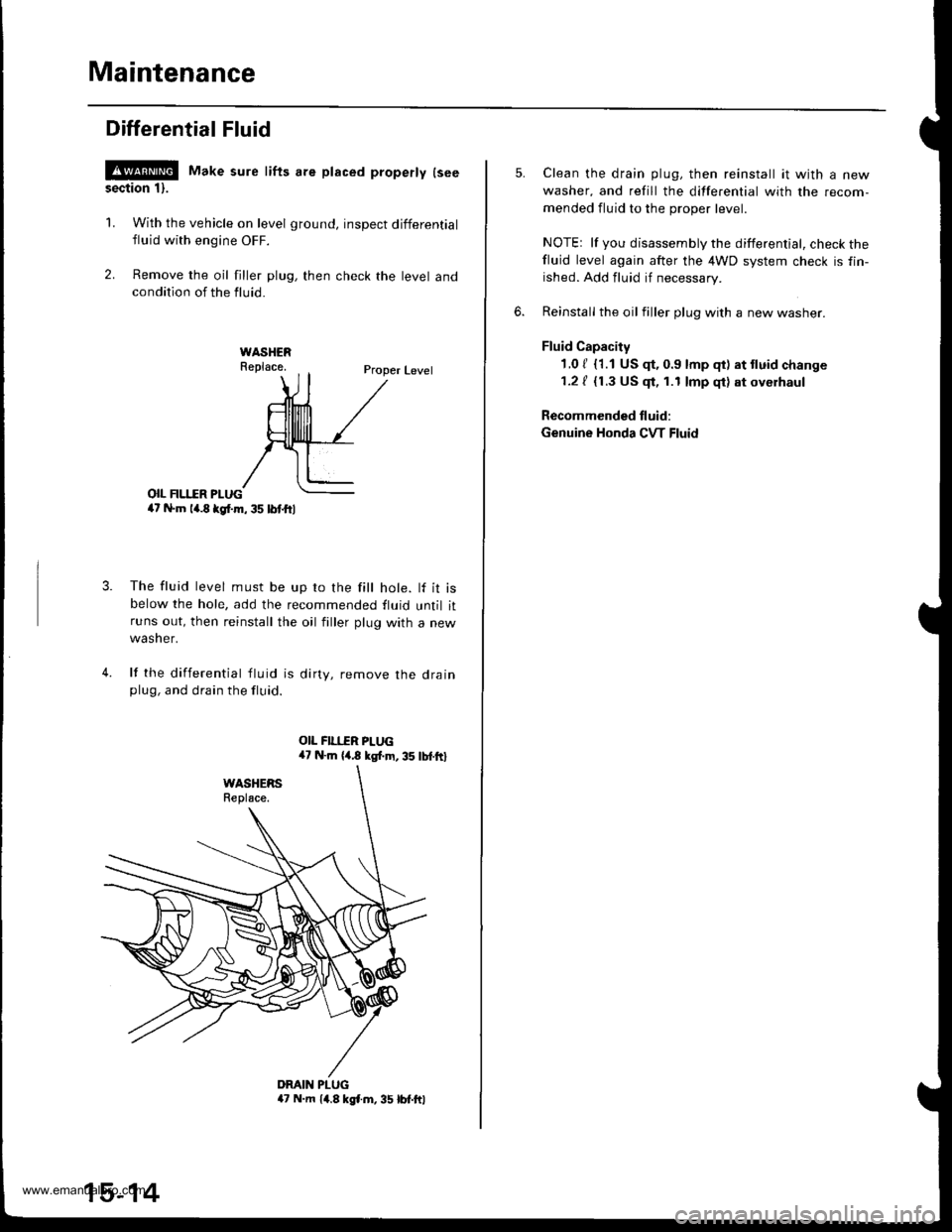
Differential Fluid
!@ Make sure lifts are placed properly lseesection 1).
1. With the vehicle on level ground, inspect differential
fluid with engine OFF.
2. Remove the oil filler plug, then check the level andcondition of the fluid.
Proper Level
o|I FII.IIR PI-UG4t N.m la.8 kgl.m, 35 lbl.ftl
The fluid level must be up ro the fill hole. lf it isbelow the hole, add the recommended fluid until itruns out, then reinstall the oil filler plug with a new
wasner.
lf the differential tluid is dirty, remove the drainplug, and drain the fluid.
4.
DMIN PLUGa7 N.m 14.8 kgl.m, 35 lbt.ftl
15-14
Clean the drain plug, then reinstall it with a new
washer, and refill the differential with the recom-
mended fluid to the proper level.
NOTEr lf you disassembly the differential, check thefluid level again after the 4WD system check is fin-
ished. Add fluid if necessary.
Reinstall the oil filler plug with a new washer.
Fluid Capacity
1.0 / {1.1 US $, 0.9 lmp qt) at tluid change
1.2 / {1.3 US $, 1.1 lmp qt) at oyerhaul
Recommended fluid:
Genuine Honda CVT Fluid
www.emanualpro.com
Page 833 of 1395
Front DriveshaftsIntermediate Shaft
Installation {cont'd}
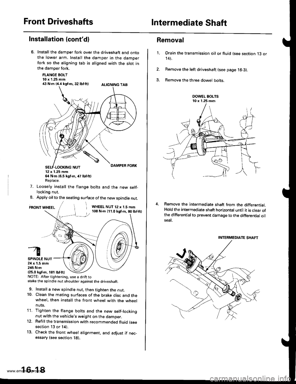
Install the damper fork over the driveshaft and ontothe lower arm. Install the damper in the damperfork so the aligning tab is aligned with the slot inthe damper fork.
FLANGE BOLT10 x 1.25 mm€ N.m {4.i1kst.n,32 lbf.ftl ALtcNtNG TAB
12x 1.25 mm64 N.m {6.5 kgf.m, 47 lbf.ftlReplace.
7. Loosely install the flange bolts and the new self-locking nut.
8. Apply oil to the seating surface of the new spindle nut.
FRONT WHEELi WHEEL NUT 12 x 1.5 mm108 N.m (11.0 kgf.m,80lbf.ftl
SPINDLE NUT24 x 1.5 mm245 N.m{25.0 ksf.m, 181 lbf.ft)NOTE: Atter tightening. use a drift tostake the spindle nut shoulder against the driveshaft.
9. Install a new spindle nut, then tighten the nut.10. Clean the mating surfaces of the brake disc and thewheel. then install the front wheel with the wheelnuts,
1'1. Tighten the flange bolts and the new setf-lockingnut with the vehicle's weight on the damper.12. Refill the transmission with recommended fluid (see
section 13 or 14).
13. Check the front wheel alignment. and adjust if nec-essary (see section 18).
16-18
1.
Removal
Drain the transmission oil or fluid (see section 13 or14).
Remove the left driveshaft (see page 16-3).
Remove the three dowel bolts.
Remove the intermediate shaft from the differential.Hold the intermediate shaft horizontal until it is clear ofthe differentialto prevent damage to the differential oilseal.
INTERMEDIATE SHAFT
www.emanualpro.com