fuse box HONDA CR-V 1998 RD1-RD3 / 1.G Repair Manual
[x] Cancel search | Manufacturer: HONDA, Model Year: 1998, Model line: CR-V, Model: HONDA CR-V 1998 RD1-RD3 / 1.GPages: 1395, PDF Size: 35.62 MB
Page 975 of 1395
![HONDA CR-V 1998 RD1-RD3 / 1.G Repair Manual
Troubleshooting
DTG 54: Main Relay
IWHT/GRNI
AAS CONTROL UNIT 26P CONNECTON
Wire side of female terminals
ABS COf{TROL UN]T 22P CONNECTOR
PCOMIGRN/WHTIscoM{BLK/WHTI
Wire side of female terminals
- Wi HONDA CR-V 1998 RD1-RD3 / 1.G Repair Manual
Troubleshooting
DTG 54: Main Relay
IWHT/GRNI
AAS CONTROL UNIT 26P CONNECTON
Wire side of female terminals
ABS COf{TROL UN]T 22P CONNECTOR
PCOMIGRN/WHTIscoM{BLK/WHTI
Wire side of female terminals
- Wi](/img/13/5778/w960_5778-974.png)
Troubleshooting
DTG 54: Main Relay
IWHT/GRNI
AAS CONTROL UNIT 26P CONNECTON
Wire side of female terminals
ABS COf{TROL UN]T 22P CONNECTOR
PCOMIGRN/WHTIscoM{BLK/WHTI
Wire side of female terminals
- With the ignition switch ON(lll, the ABS indicator doesnot go off.- With the SCS service connec-tor connected {see page 19-381,DTC 54 is indicatod.
Check the ABS +B 120 A) fuse inthe under-hood ABS luse/relaybox, and reinstall the fuse if it isoK.
FeDlace the tu3e and recheck.
Ch€ck tor an open in the 81, 82circuit:Measure the voltage betweenbody ground and the ABS controlunit 26P connector terminal No. 14and No. 15 individually.
Repair open in the wiro bstweonth6 ABS conirol unit and theunder-hood ABS fuse/rolay box,
ls there battery voltage?
Check for a short to body groundin the PMR circuit:L Turn the ignition switch OFF.2. Remove the pump motor relay.3. Disconnect the ABS controlunit 22P connector.4. Check lor continuity betweenterminal No. 19 and bodygrouno.
Repair short to body ground inthe wire betweon the under-hood ABS lGe/r.lay box and theABS control unit.
Check for a short to body groundin the PCOM, SCOM cilcuit:1. Disconnect the ABS controlunit 26P connector.2. Check tor continuity betweenbody ground and the ABS con-trol unit 26P terminals No- 1and No.2 individually.
. R€pair short to body ground inth€ P1COM circuit wire betweenthe ABS control unit and theund6r-hood ABS tuse/r6layoox.. R6p.ir short to body ground inthe PCOM or SCOM circuit wirebetweon th6 ABS control unitand lhe mod!lator unit.. R.Dlece tho modulrtor unit.(Short circuit inside the unitl
ls there continuity?
(To page 19-53)
www.emanualpro.com
Page 1034 of 1395
Dashboard Removal and Installation
SRS components are located in this area. Review the SRS
component locations, precautions, and procedures in the
SRS section {24) before preforming repairs or service.
CAUTION:
. When prying with a flat-tip screwdriver, wrap h withprotective tap€, and apply protective tape around the
related parts to prevgnt damage.
. Put on gloves to prot€ct your hands.
NOTE:
. An assistant is helpful when removing and installing
the dashboard.
. Take care not to scratch the dashboard, bodv and
other related parts.
1.Make sure you have the anti-theft code for the
radio, then write down the frequencies for the
radio's preset buttons.
Disconnect the negative battery cable. and wait at
least three minutes before beginning work.
Removei
a Driver's dashboard lower cover and knee bolster(see page 20-48)
. Glove box (see page 20-49)
. Lower console cover and center pocket (A/T
model, see page 20-49)
. Center console and center upper pocket (M/T
model, see page 20-47)
. Center dashboard lower cover (see page 20-50)
. Power window switch (see page 20-51)
. Driver's side air vent (see page 20-52)
. Driver's side defogger trim (see page 20-52)
Disconnect the driver's airbag connector, and lower
the steering column (see section 17)
NOTE: To prevent damage to the steering column,
wrap it with a shop towel.
2.
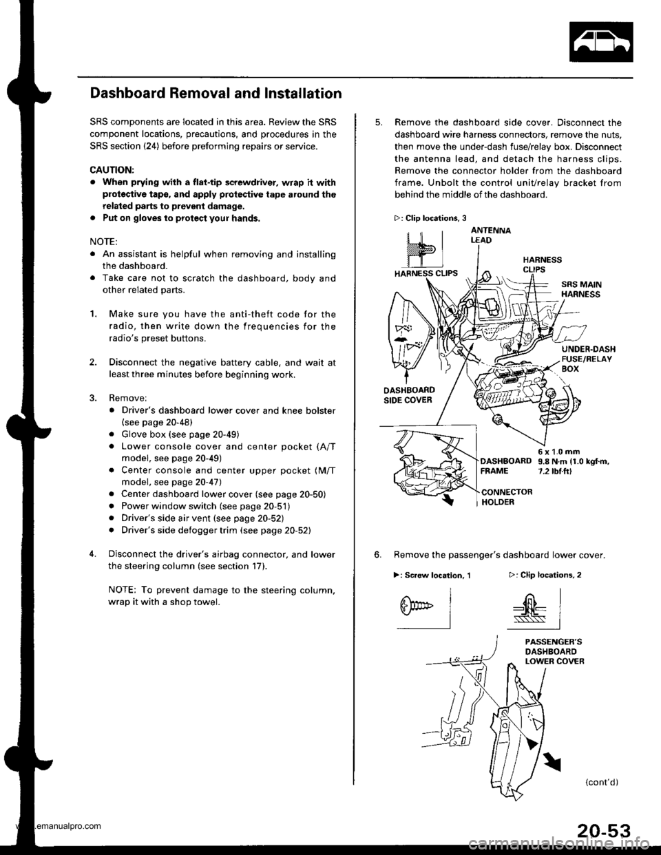
5. Remove the dashboard side cover. Disconnect the
dashboard wire harness connectors, remove the nuts,
then move the under-dash fuse/relay box. Disconnect
the antenna lead, and detach the harness clips.
Remove the connector holder from the dashboard
frame. Unbolt the control unit/relay bracket from
behind the middle of the dashboard.
HARNESS
6. Remove the passenger's dashboard lower cover.
D: Clip locations,
nl
-$t- Issj
I
ANTENNALEAD
>: Clip locations.
rttl
slllll
>: Scr€w location, 1
I
SF:oo I-l
SRS MAINHARNESS
UNDER.DASHFUSE/RELAYBOX
OASHBOARDSIDE COVER
6x1.0mm9.8Nm11.0kgf.m,7.2tbt.ftlDASHBOARDFFAME
CONNECTORHOLDER
PASSENGER'SDASHBOARDLOWER COVER
{cont'd)
www.emanualpro.com
Page 1095 of 1395
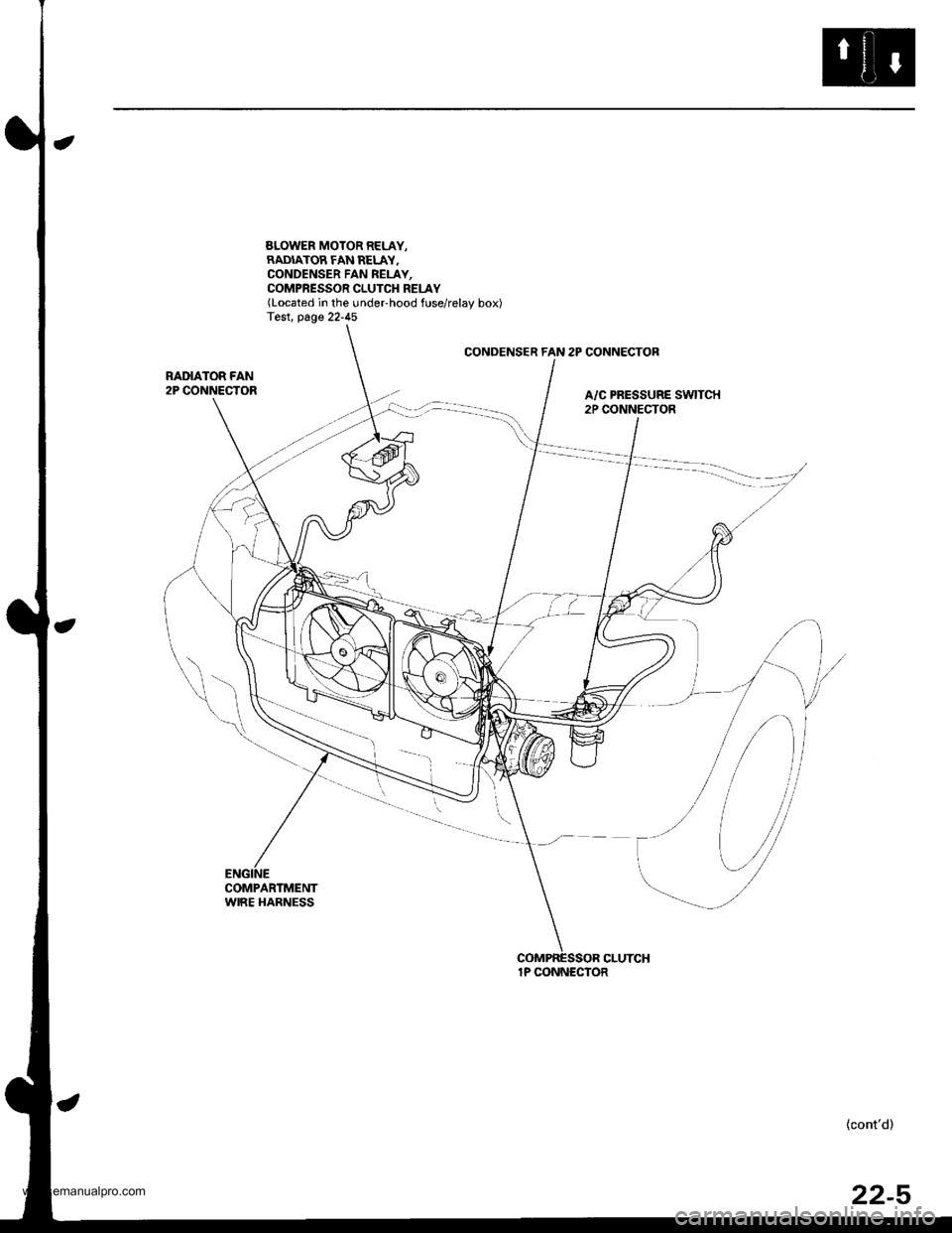
SLOWER MOTOR RELAY,RADIATOR FAN RELAY.CONDENSER FAN REI-AY,COMPRESSOR CLUTCH RELAY(Located in the undeFhood fuse/relay box)Test. page 22-45
CONDENSER FAN 2P CONNECTOB
RADIATOR FAN2P CONNECTORA/C PRESSURE SWITCH2P CONNECTOR
COMPARTMENTWIRE HARNESS
{cont'd)
1P CONNECTOR
22-5
www.emanualpro.com
Page 1098 of 1395
Circuit Diagram
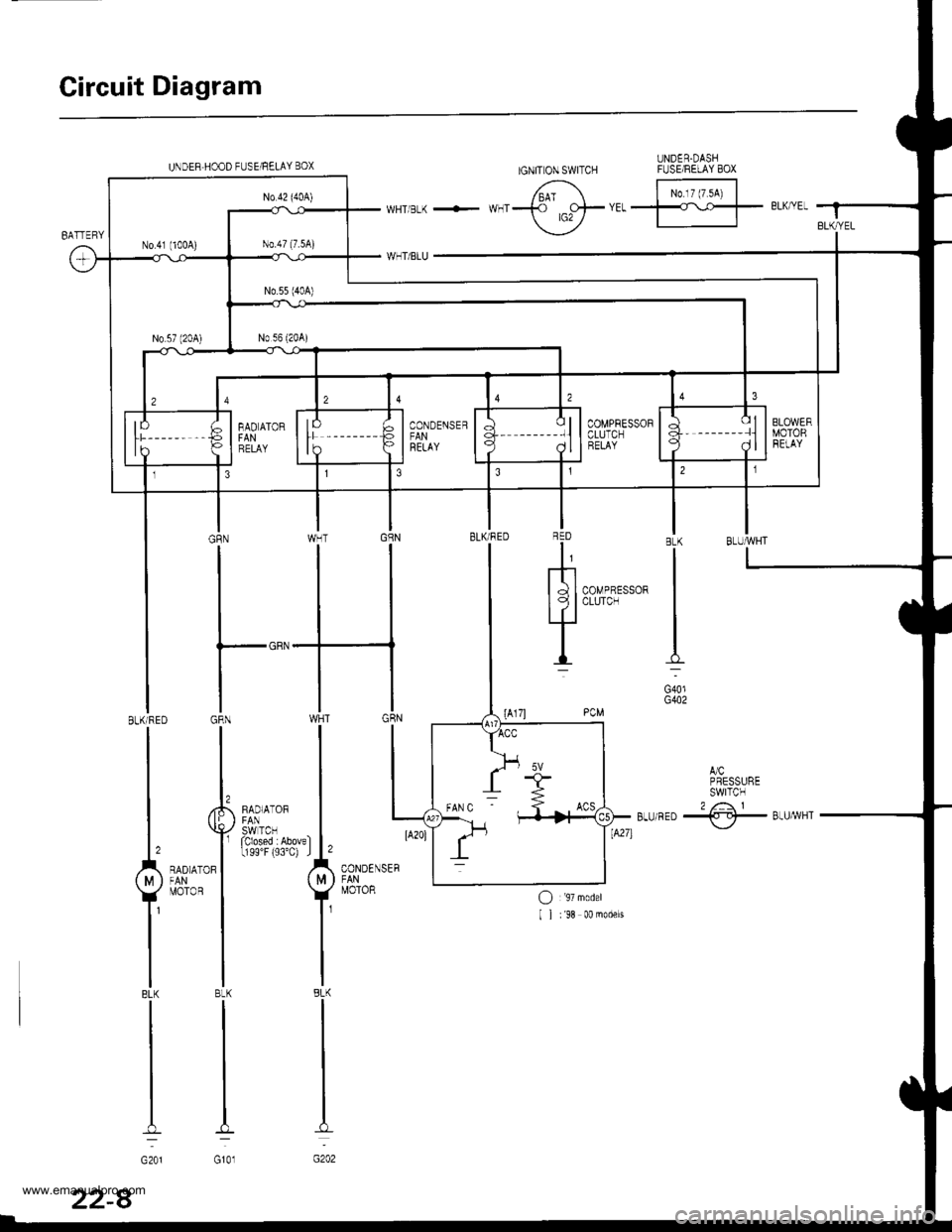
UNDER.DASHFUSEiRELAY BOXIGNIT ON SWITCHUNDEB HOOD FUSE/RELAY BOX
/6'^' F;t"^i IwHTBLK + **f ,o+trrffl- eLK/YEI f
\_-./
,JCPRESSURESWITCN2 /: 1Btu/RED -{.-!}- Btu/yvHT\,-/
BLU'ryVHTBLK
G401G402
RED
I,
mI d I CoMPRESSORI I I CLUTCH
LIl
I
CONDENSER
MOTOR
BLK/RED GRN WHT
I I,^,^,", I
L^"^,Y**t,|
T*.'1 Y
lllBLK BLK BLK
rtl
lll---
G201 G101 G202
COMPRESSOFCLUTCHRELAY
22-8
www.emanualpro.com
Page 1100 of 1395
Troubleshooting
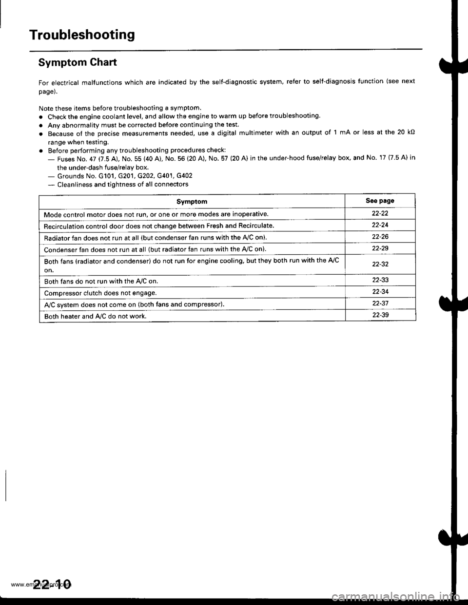
Symptom Ghart
For electrical malfunctions which are indicated by the self-diagnostic system, reter to selt-diagnosjs function (see next
page).
Note these items before troubleshooting a symptom.
. Check the engine coolant level, and allow the engine to warm up before troubleshooting.
. Anv abnormality must be corrected before continuing the test.
. Because of the precise measurements needed, use a digital multimeter with an output of 1 mA or less at the 20 kO
range when testing.
. Before performing any troubleshooting procedures check:
- Fuses No. 47 17.5 AJ, No. 55 (40 A), No. 56 (20 A), No. 57 (20 A) in the under-hood fuse/relay box, and No. 17 {7.5 A) in
the under-dash fuse/relay box.._ Grounds No. G101, G201, G202, G401, G4O2
- Cleanliness and tightness of all connectors
SymptomSse pags
Mode control motor does not run, or one or more modes are inoperative.
Recirculation control door does not change between Fresh and Recirculate.22-24
Radiator fan does not run at all (but condenser fan runs with the AVC on).
Condenser fan does not run at all {but radiator fan runs with the Ay'C on).22-29
Both fans (radiator and condenser) do not run for engine cooling. but they both run with the A,/C
on.
Both fans do not run with the Ay'C on22-33
Compressor clutch does not engage.22-34
AJC svstem does not come on (both fans and compressor).22-37
Both heater and A/C do not work,22-39
22-10
www.emanualpro.com
Page 1106 of 1395
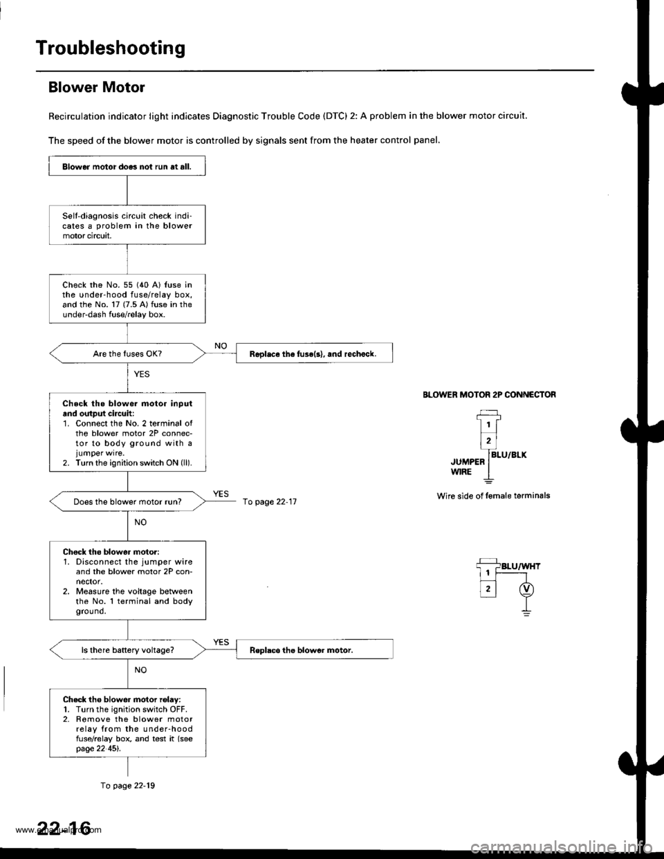
Troubleshooting
Blower Motor
Recirculation indicator light indicates Diagnostic Trouble Code (DTC) 2: A problem in the blower motor circuit.
The speed of the blower motor is controlled by signals sent from the heater control panel,
BLOWER MOTOR 2P CONNECTOR
JUMPEFw|RE
Wire side of lemale terminals
Blower motor do.3 not run at all.
Selt-diagnosis circuit check indi-cates a problem in the blowermotor circuit,
check rhe No. 55 (40 A) {use inthe under-hood fuse/relay box,and the No. 17 (7.5 A) fuse in theunder-dash fuse/relay box.
Replace th6 fuse(s), and rechalck.
Check tho blowe. motor inputand output cilcuh:1. Connect the No. 2 terminal ofthe blower motor 2P connec-tor to body ground with ajumper wrre.2. Turn the ignition switch ON (ll).
Does the blower motor run?
Chock the blower moto.:1. Disconnect the jumper wireand the blower motor 2P con-nector.2. Measure the voltage betweenthe No. l terminal and bodygrou nd.
Check tho blower motor rolay:1. Turn the ignition switch OFF.2. Romove the blower motorrelay from the under-hoodfuse/relay box, and test it (seepage 22 45l'.
fo page 22-11
fo page 22-19
22-16
www.emanualpro.com
Page 1112 of 1395
Troubleshooting
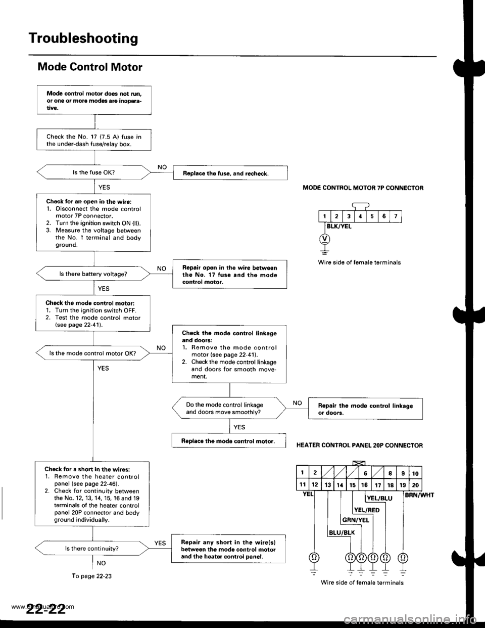
Mode Control Motor
NO
MODE CONTROL MOTOR 7P CONNECTOR
13I5
BLK/YEL
Wire side of female terminals
HEATER CONTROL PANEL 2OP CONNECTOR
BRN/WHT
Wire side of female terminals
Mode control motol does not run.or ono or more modes are inoD€aa-
Check the No. 17 {7.5 A) Iuse inthe under-dash fuse/relay box.
Replace the tus€, snd iecheck.
Chock tor an open in th€ wi.6:1. Disconnect the mode controlmotor 7P connector.2. Turn the ignition switch ON (ll).3. Measure the voltage betweenthe No. l terminal and bodyground.
Repair opon in the wire betwoontho No. 17 luse and tho modecontrol motor.
Check the mode control motor:1. Turn the ignition switch OFF.2. Test the mode control motorGee page 22 41') .
Chock th€ mode cont.ol link.geand doors:1. Remove the mode controlmotor (see page 22-41).2. Check the mode control linkageand doors for smooth move-ment,
ls lhe mode control motor OK?
Do the mode control linkageand doors move smoothly?
Replece the inod6 control motor.
Chock for s shon in the wir€s:1. Remove the heater controlpanel (see page 22'46).2. Check for continuity betweenthe No. 12, 13, 14, 15, 16 and 19terminals ol the heater controlpanel 20P connector and bodyground individuaily.
Repair any short in the wire(slbetween the mode control rnotoaand the h6ater control Danel.
ls there continuity?
2l,/1,/8I10
111213ta151617r81320
BLU
[E!r!
YEL/RED
Ii
To page 22-23
www.emanualpro.com
Page 1114 of 1395
Troubleshooting
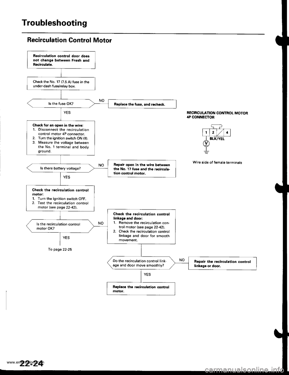
Recirculation Gontrol Motor
YES
To page 22-25
REORCULATION CONTROL MOTOR,rP CONNESTOR
q?- T--- V-l
l1, lrl/l1lI BI.IUYEL(v)
+
Wire side of female terminals
Rocirculation control door do6snoi chango botw€en Fresh andReci.culate.
Check the No. 17 {7.5 A)tuse in theunder-dash f use/relay box.
Roplace the fu36, and rechock.
Check for .n open in the wire:1. Disconnect the recirculationcontrol motor 4P connector.2. Turn the ignition switch ON (ll).3. Measure the voltage betlveenthe No. l terminal and bodyground.
Repair op6n in the wire bdtweenthe No. 17 fuse and thc recircule-tion control motor.
Check the rocirculation controlmoior:1. Turn the ignition switch OFF.2. Test the recirculation controlmotor (see page 22-42).
Chock ths r.circulation controllinkag. end doori1. Remove the recirculation con-trol motor (see page 22,42).2. Check the recirculation controllinkage and door for smooth
Do the recirculation control linkage and door move smoothly?Boprir the recirculrtion controllinkag. or dooJ,
www.emanualpro.com
Page 1116 of 1395
Troubleshooting
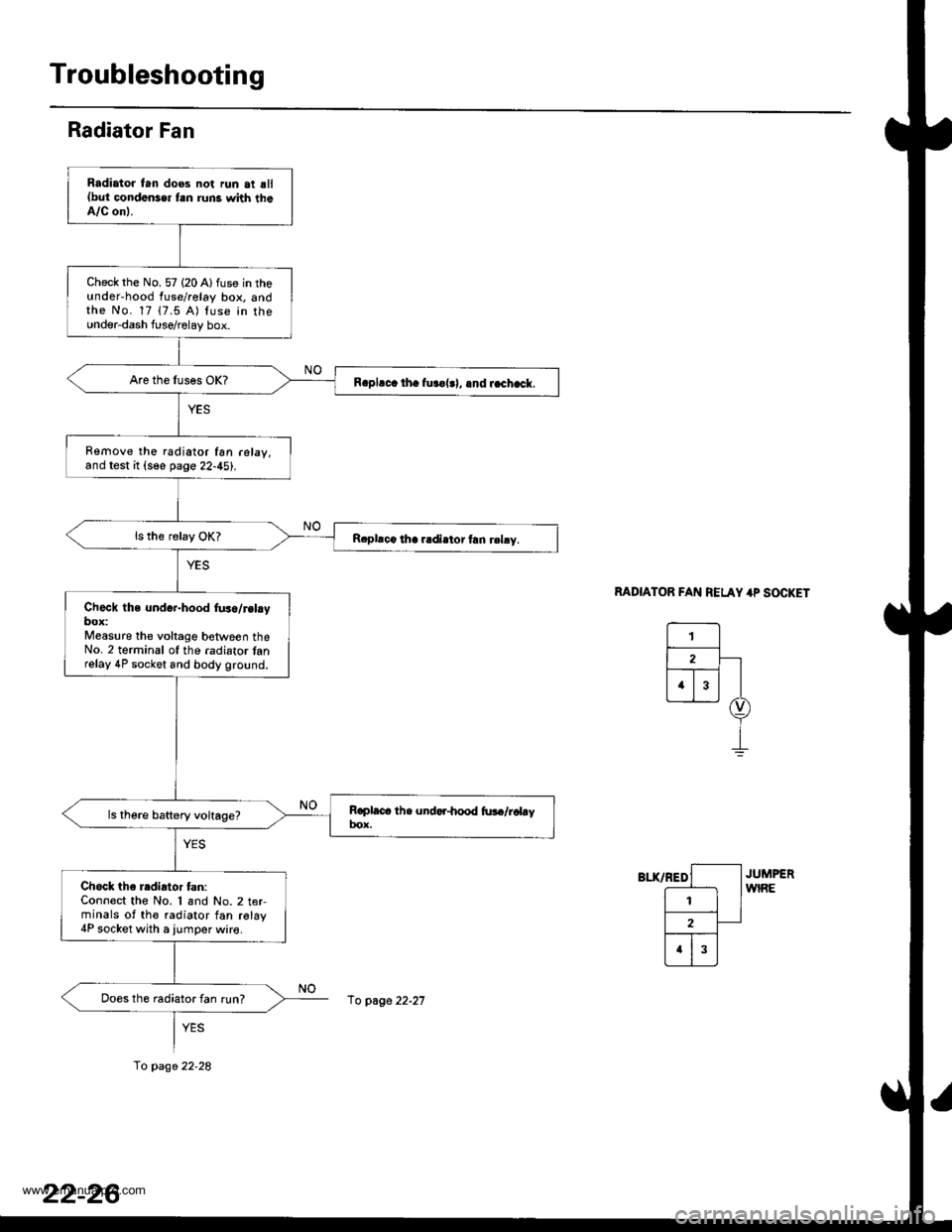
Radiator Fan
MDIATOR FAN RELAY 4P SOCKET
Radiator tan doos not run at sll(but condonser fsn runs with theA/C onl.
Check rhe No. 57 (20 Alfuse in theunderhood fuse/relay box, andthe No. 17 17.5 A) luse in the0nder-dash fuserelay box.
R.pl.c. th. fur€|.l, .nd r.chack.
Remove the radiator fan r6lay,and test it {see page 22-45).
R.pllco tha r.diator frn rehy.
Check the und.r-hood fus./r.l.ybox:Measure the voltage between theNo. 2 terminal ol the .adiator tanrelay 4P socket and body ground.
Chock the radiator tan:Connect the No. 1 and No.2 t€rminals of the radiator fan relay4P socket with a iumper wire.
Does th6 radiator fan run?
fo page 22-28
fo page 22-21
www.emanualpro.com
Page 1119 of 1395
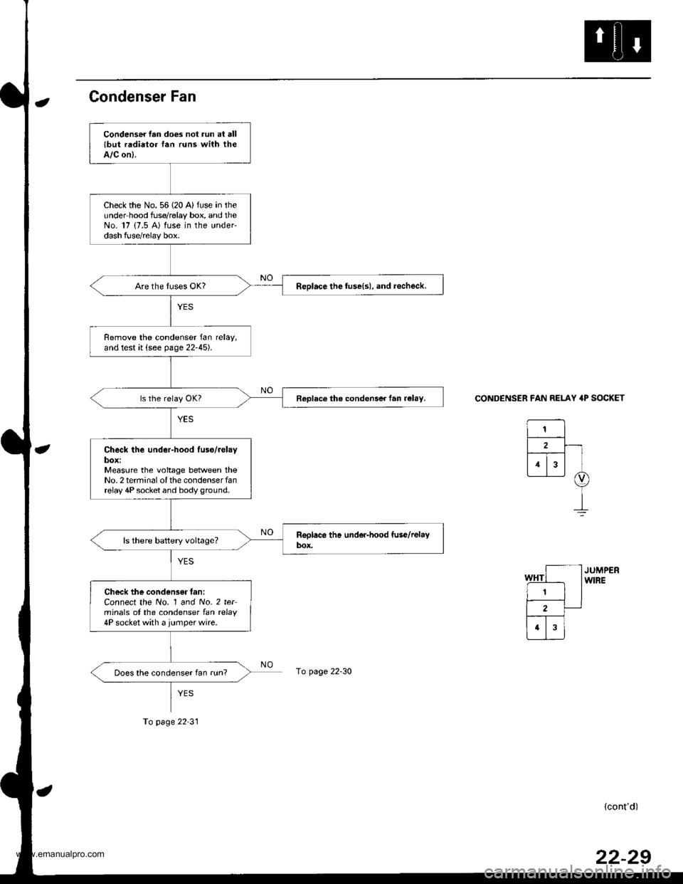
Condenser Fan
CONDENSER FAN RELAY 4P SOCKET
(cont'd)
Condenser lan does not run at alllbut radiator fan runs with theA/C on).
Check the No. 56 (20 A) fuse in theunder hood fuse/relay box, and theNo. 17 {7.5 A) fuse in the under-dash fuse/relay box.
Replace the luse(s), and .echeck.
Remove the condenser fan relay,and test it (see page 22-45).
Replace the condenser fan r€lay.
Check the under-hood luso/relaybox:Measure the voltage between theNo.2 terminal of the condenserfanrelay 4P socket and body ground.
Check the condensff fan:Connect the No. 1 and No. 2 terminals of the condenser lan rclay4P socket with a jumperwire.
Does the condenser fan run?page 22-30
To page 22 31
22-29
www.emanualpro.com