Atf HONDA CR-V 1998 RD1-RD3 / 1.G Repair Manual
[x] Cancel search | Manufacturer: HONDA, Model Year: 1998, Model line: CR-V, Model: HONDA CR-V 1998 RD1-RD3 / 1.GPages: 1395, PDF Size: 35.62 MB
Page 728 of 1395
Sub-shaft Bearings
Replacement
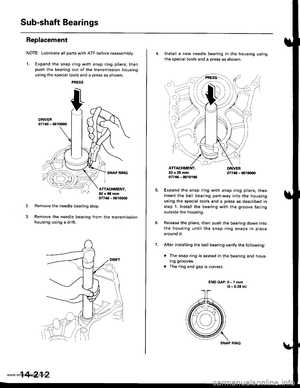
NOTE: Lubricate all parts with ATF before reassembly.
1. Expand the snap ring with snap ring pliers. thenpush the bearing out of the transmission housing
using the special tools and a press as shown.
Remove the needle bearing stop.
Remove the needle bearing from the transmission
housing using a drift.
ATTACHMENT,ai:l x 68 mm07746 - 00105q)
14-212
SNAP RING
4. Install a new needle bearing in the housing using
the sOecial tools and a oress as shown.
7.
cI
32x35mm077/46 - qt10t(x,
Expand the snap ring with snap ring pliers, then
insert the ball bearing part-way into the housing
using the special tools and a press as described in
step 1. Install the bearing with the groove facing
outside the housing.
Release the pliers, then push the bearing down into
the housing until the snap ring snaps in place
around it.
After installing the ball bearing verify the fottowing:
. The snap ring is seated in the bearing and hous-
Ing grooves.
. The ring end gap is correct.
ENDGAP:0-7mml0 - 0.28 inl
www.emanualpro.com
Page 733 of 1395
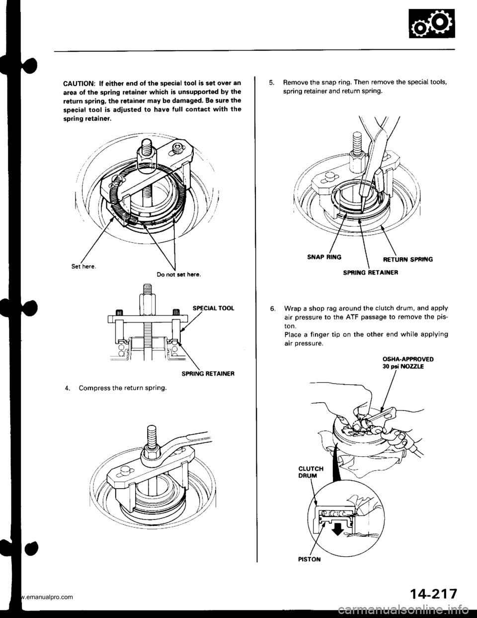
CAUTION: lf either end ot the special tool issetover an
area of the spring retainer which is unsupported by the
return spring, the retainer may be damaged. B€ sure the
special tool is adiusted to have lull contact with the
spring retainer.
SPRING RETAINER
4. Compress the return spring.
Do not s6t h6re.
5. Remove the snap ring, Then remove the special tools,
spring retainer and return spring.
Wrap a shop rag around the clutch drum, and apply
air pressure to the ATF passage to remove the pis-
ton.
Place a finger tip on the other end while applying
arr pressure.
OSHA.APPROVED
SPRIlIG RETAINER
14-217
www.emanualpro.com
Page 734 of 1395
Glutch
Reassembly
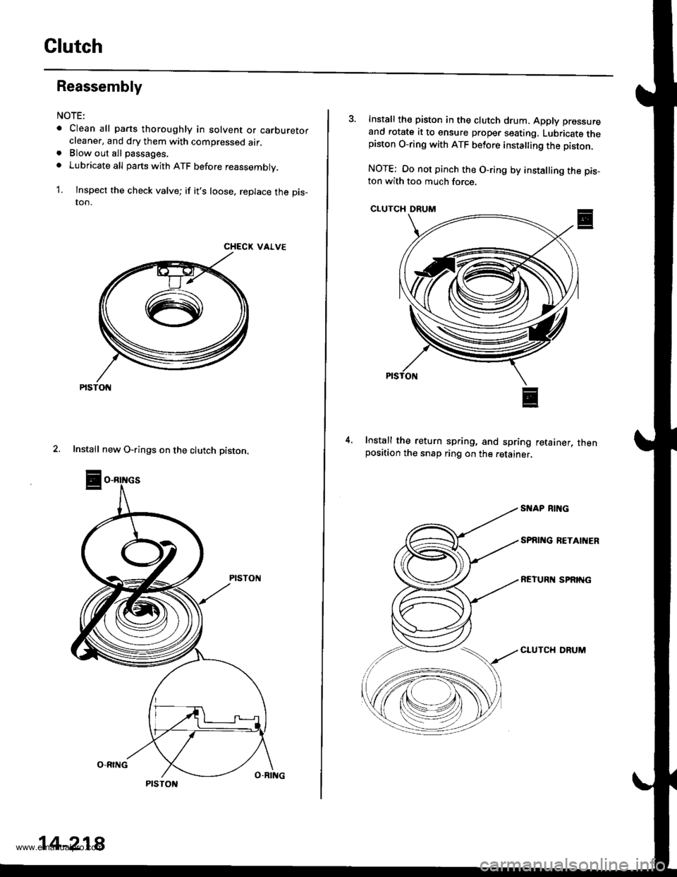
NOTE:
. Clean all parts thoroughly in solvent or carburetorcleaner, and dry them with compressed air.. Blow out all passages.
o Lubricate all parts with ATF before reassembly.
1. Inspect the check valve; if it's loose, replace the pis_ton.
CHECK VALVE
2. Install new O-rings on the clutch piston.
PtsTot{
14-218
3. Install th€ piston in the clutch drum. Apply pressure
and rotate it to ensure proper seating, Lubricate thepiston O-ring with ATF betore insta ing the piston.
NOTE: Oo not pinch the O-ring by installing the pis_ton with too much force.
CLUTCH DRUM
Install the return spring, and spring retainer, thenposition the snap ring on the retainer.
4.
SI{AP RING
SPAI'{G RETAIIIER
REIURN SPRING
CLUTCH DRUM
www.emanualpro.com
Page 736 of 1395
Clutch
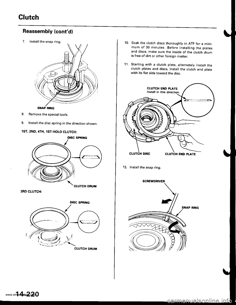
Installthe snap ring.
Reassembly (cont'd)
7.
S AP RIIG
8. Remove the special tools.
9, Install the disc spring in the direction shown.
1ST, 2ND, 4TH, lST-HOLD CLUTCH:
3RD CLUTCH:
Dlsc sPRrrtc
CIUTCH ORUM
otsc sPfitl{c
14-220
10.Soak the clutch discs thoroughly in ATF for a mini_mum of 30 minutes. Before installing the platesand discs, make sure the inside of the clutch drumis free of din or other foreign matter
Starting with a clutch plate, alternatelv install theclutch plates and discs. Install the clutch end platewith its flat side toward the disc.
CLUTCH EI{D PI.ATEInstall in this directior.
CLUTCHCLUTCH EI{D PLATE
12. Install the snap ring.
SCREWDRIVER
't1.
www.emanualpro.com
Page 743 of 1395
Transmission Housing Bearings
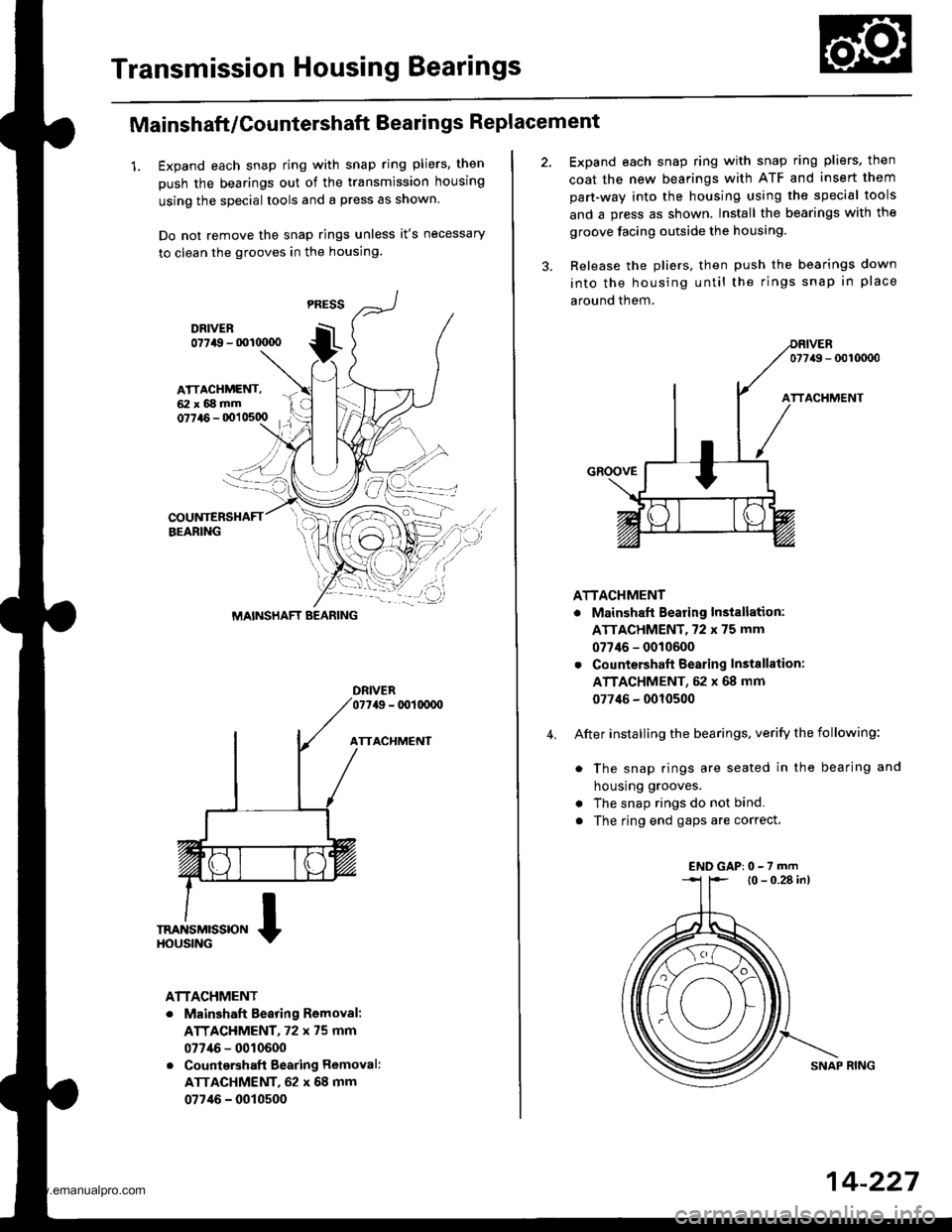
Mainshaft/Countershaft Bearings Replacement
1. Expand each snap ring with snap ring pliers, then
push the bearings out of the transmission housing
using the special tools and a press as shown.
Do not remove the snap rings unless it's necessary
to clean the grooves in the housing.
DFIVER077a9 - 001(xx)o
ATTACHMENT
ATTACHMENT
. Mainshaft Bearing Romoval:
ATTACHMENT, 72 x 75 mm
077/16 - 0010600
. Countqrshaft Bearing Removal:
ATTACHMENT, 62 x 68 mm
07746 - 0010500
MAINSHAFT BEARING
4.
Expand each snap ring with snap ring pliers, then
coat the new bearings with ATF and insert them
part-way into the housing using the special tools
and a press as shown. Install the bearings with the
groove facing outside the housing.
Release the pliers, then push the bearings down
into the housing until the rings snap in place
around them.
077/49 - 0010000
ATTACHMENT
. Mainshaft Bearing Installation:
ATTACHMENT,72 x 75 mm
07746 - 0010600
. Countershaft Bearing Instsllation:
ATTACHMENT, 52 x 68 mm
077'16 - 0010500
After installing the bearings, verify the following:
. The snap rings are seated in the bearing and
housrng grooves.
. The snap rings do not bind.
. The ring end gaps are correct,
l0 - 0.28 in)
SNAP RING
ENDGAP:0-7rnm
14-227
www.emanualpro.com
Page 744 of 1395
Transmission Housing Bearings
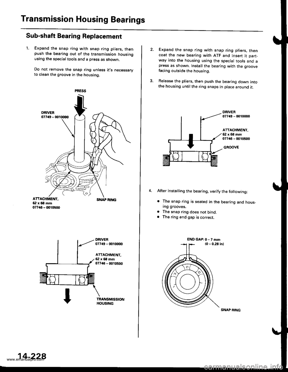
Sub-shaft Bearing Replacement
1. Expand the snap ring with snap ring pliers, thenpush the bearing out of the transmission housingusing the special tools and a press as shown.
Do not remove the snap ring unless it,s necessaryto clean the groove in the housing.
ATTACHMEI{T,5:l x 68 mm07r{5 - @10500
SNAP RI]TG
DRIVER07749 - tDl(xx)o
ATTACHMENT,6:l x 68 mm077a6 - (X,r0500
14-228
SNAP RING
Expand the snap ring with snap ring pliers, thencoat the new bearing with ATF and insert it part-way into the housing using the special tools and apress as shown. lnstall the bearing with the groovefacing outside the housing.
Release the pliers, then push the bearing down intothe housing untilthe ring snaps in place around it.
DRIVER07743 - 0010mo
ATTACHMENT,{i:l x 68 mm07746 - 0010500
GROOVE
After installing the bearing, verify the following:
. The snap rjng is seated in the bearing and hous_ing grooves.
. The snap ring does not bind.. The ring end gap is correct,
ENDGAP:0-7mm
www.emanualpro.com
Page 746 of 1395
Torque Gonverter Housing
BearingsGontrol Lever Assembly
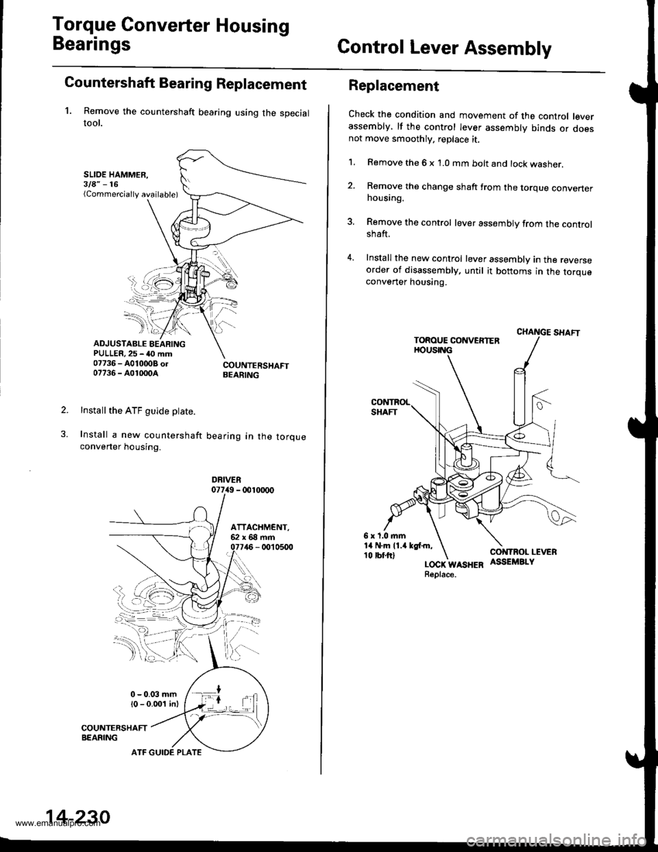
Countershaft Bearing Replacement
1. Remove the countershaft bearing using the specialtool.
SLIOE HAMMER,3la" -16(Commercially available)
ADJUSTABLE BEARINGPULLER,25 - 40 mm07736 - A0100OB ol07736 - A01m0A
Install the ATF guide ptate.
Install a new countershaft
converter housing.
COUNTERSHAFTBEARING
bearing in the torque
DRIVER077i19 - 001m00
14-230
ATF GUIDE PLATE
Replacement
Check the condition and movement of the control leverassembly, lf the control lever assembly binds or doesnot move smoothly. replace it.
1. Remove the 6 x 1.0 mm bolt and lock washer.
2. Remove the change shaft trom the torque converterhousing.
3. Remove the control lever assembly from the controlshaft.
4. Install the new control lever assembly in the reverseorder of disassembly, until it bottoms in the torqueconverter housing.
LOCK WASHERReplace.
www.emanualpro.com
Page 753 of 1395
Transfer Drive Gear Bearing
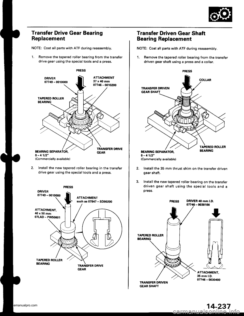
Replacement
NOTE: Coat all parts with ATF during reassembly.
1. Remove the tapered roller bearing from the transfer
drive gear using the special tools and a press.
(Commercially available)
Install the new tapered roller bearing in the transfer
drive gear using the specialtools and a press.
ATTACHMENT,l()x50mm
07LAD - PWSo6o1
GEAR
14-237
Transfer Driven Gear Shaft
Bearing Replacement
NOTE: Coat all parts with ATF during reassembly.
1. Remove the tapered roller bearing from the transfer
driven gear shaft using a press and a collar.
B€ANf{G SEPARATO0 - 1112'(Comm6rcially availablel
2. Install the 35 mm thrust shim on the transfer drivengear shaft,
3, Install the new tapered roller bearing on the transfer
driven gear shaft using the special tools and apress.
PNESSDRIVER iO mm l.D.0t7a5 - 00:I)100
I
n
ru
ATTACHMENT.35 mm l.D.0t715 - 0030400
www.emanualpro.com
Page 754 of 1395
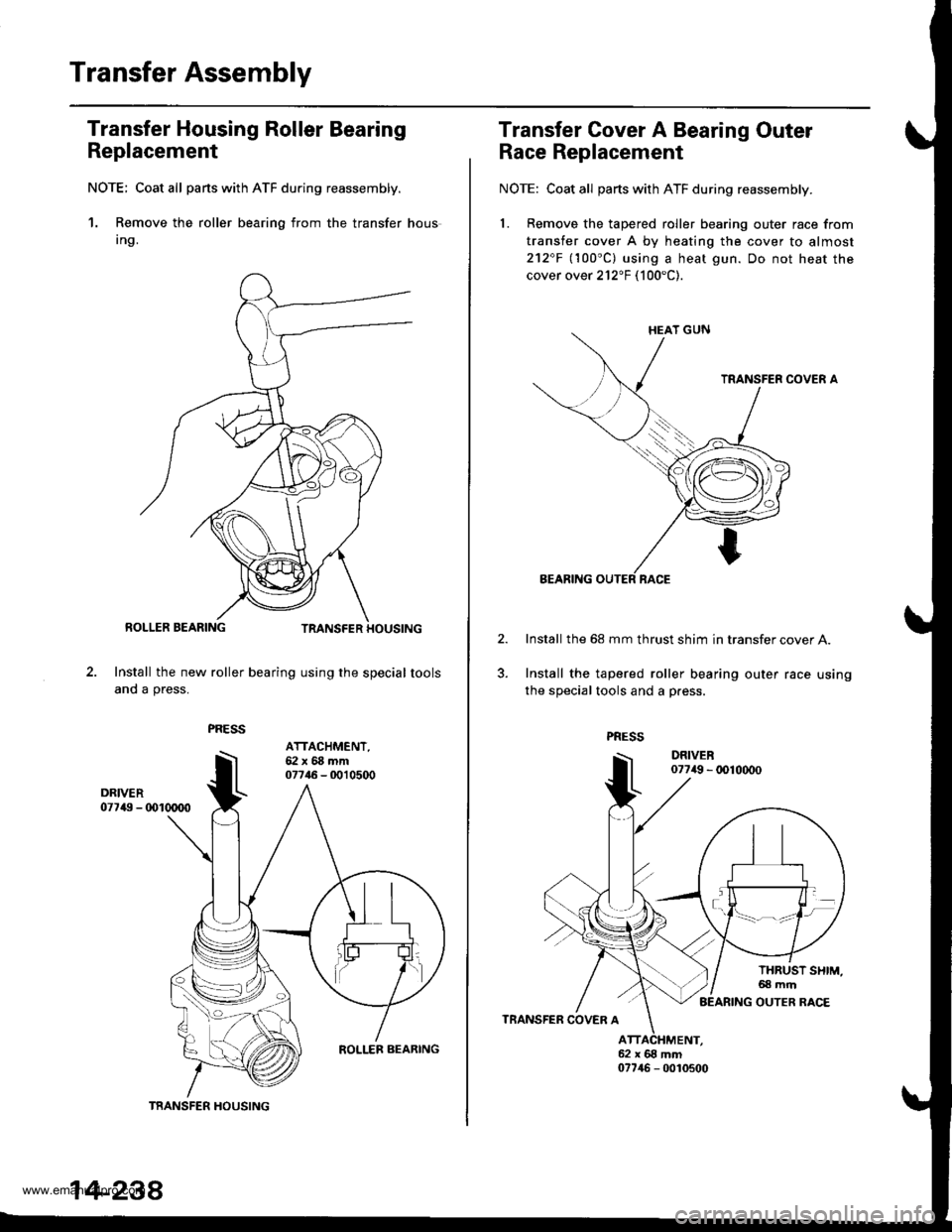
Transfer Assembly
Transfer Housing Roller Bearing
Replacement
NOTE; Coat all parts with ATF du.ing reassembly.
1. Remove the roller bearing from the transfer hous
Ing.
Install the new roller bearing using the special tools
and a press.
TRANSFER HOUSING
ATTACHMENT,62x68mm07746 - 0010500
14-238
Transfer Cover A Bearing Outer
Race Replacement
NOTE: Coat all parts with ATF during reassembly.
1. Remove the tapered roller bearing outer race from
transfer cover A by heating the cover to almost
212"F llOO"Cl using a heat gun. Do not heat the
cover over 212"F (100"C).
Install the 68 mm thrust shim in transfer cover A.
Install the tapered roller bearing outer race using
the special tools and a p.ess.
www.emanualpro.com
Page 755 of 1395
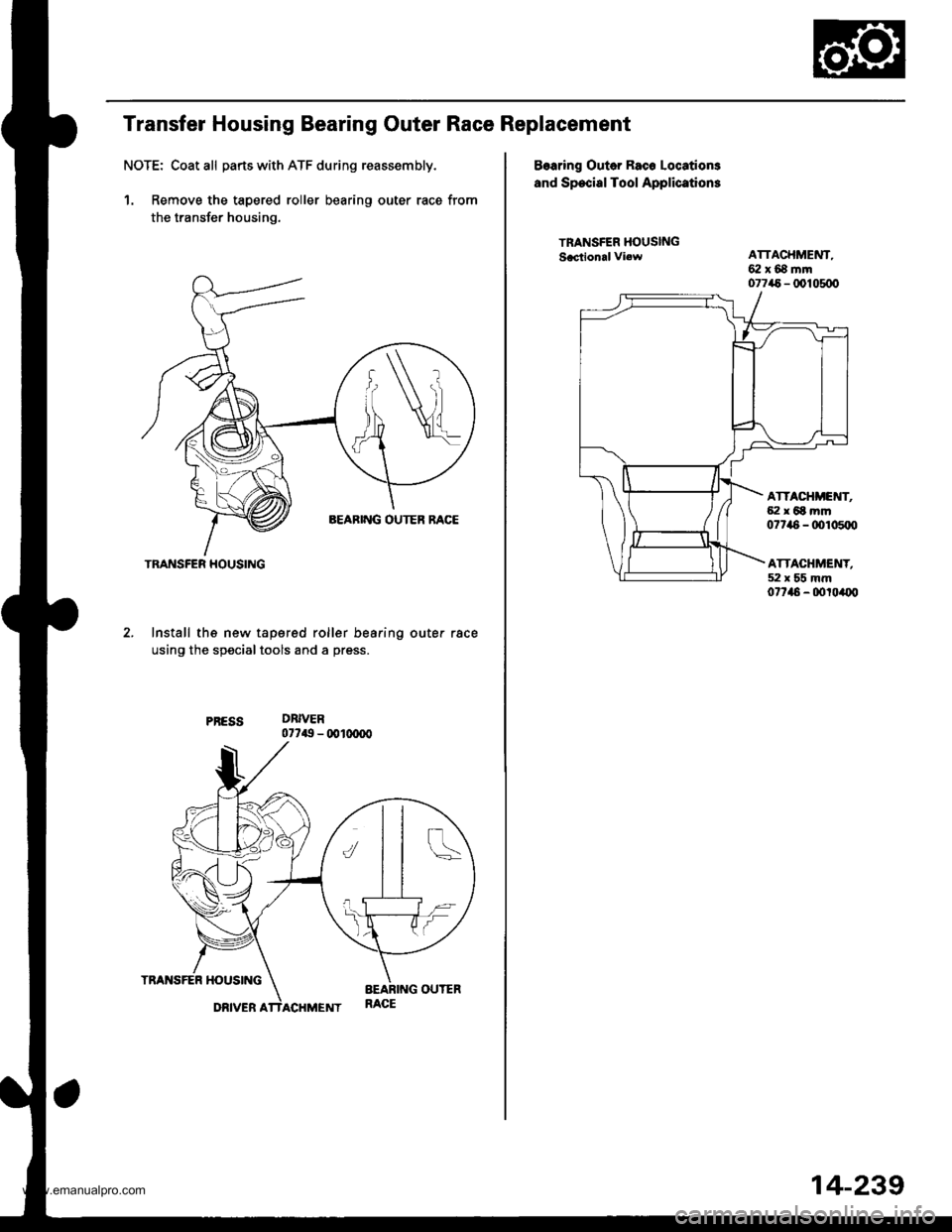
Transfer Housing Bearing Outer Race Replacement
NOTE: Coat all parts with ATF during reassembly.
1. Remove the tapered roller bearing outer race from
the transfer housing.
Install th€ new tapered roller bearing outer race
using the specialtools and a press.
DRIVER077$ - 0010(ro0
TRANSFER HOUSING
Bearing Outer Rac6 Locations
and Special Tool Applications
TRANSTER HOUSINGSacttonal vi.wATTACHMENT,62x68mm077a5 - @105dt
ATTACHI'E'{T,{i:l x 6t mm07746 - rDl05rr0
ATTACHMENT,52x55mm07t46 - dtroa{x,
14-239
www.emanualpro.com