4-34 HONDA CR-V 1998 RD1-RD3 / 1.G Workshop Manual
[x] Cancel search | Manufacturer: HONDA, Model Year: 1998, Model line: CR-V, Model: HONDA CR-V 1998 RD1-RD3 / 1.GPages: 1395, PDF Size: 35.62 MB
Page 51 of 1395
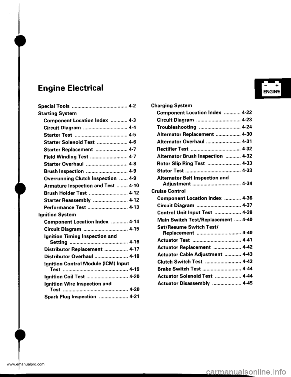
Engine Electrical
Speciaf Tools ............. 4-2
Starting System
Component Location Index ............ 4-3
Circuit Diagram ................................ 4-4
Starter Test ........... 4-5
Starter Solenoid Test ...................... 4'5
Starter Replacement ....................... 4-7
Field Winding Test ........................... 4-7
Starter Overhaul ............................,. 4-8
Brush Inspection ...........................,., 4-9
Overrunning Glutch Inspection ...... 4-9
Armature lnspection and Test ........4-10
Brush Holder Test ............................ 4-12
Starter Reassemb|y ......................... 4-1 2
Perf ormance Test ............................. 4- 1 3
lgnition System
Component Location Index ............ 4-14
Circuit Diagram ................................ 4-15
lgnition Timing Inspection and
Setting .......................................... 4-16
Distributor Replacement ........,........ 4-17
Distributor Overhaul .............,,......... 4-18
lgnition Control Module (lCM) Input
Test ..............................,................ 4-19
fgnition Coil Test .............................. 4-2O
lgnition Wire Inspection and
Test ............................................... 4-20
Spark Plug Inspection ..................... 4-21
-+
ENGINE
Charging System
Component Location Index ............ 4-22
Circuit Diagram ....................,........... 4-23
Troubleshooting .............................. 4-24
Alternator Replacement ..........,....... 4-30
Alternator Overhaul .......,,................ 4-31
Rectifier Test .........4-32
Alternator Brush Inspection ........... 4-32
Rotor Slip Ring Test ........................ 4-33
Stator Test ............. 4-33
Alternator Belt Inspection and
Adiustment ........4-34
Gruise Control
Component Location Index .,,,........ 4-36
Circuit Diagram ................................ 4-37
Control Unit Input Test ................... 4-38
Main Switch Test/Replacement ..... 4-40
Set/Resume Switch Test/
Replacement .......................,........ 4'40
Actuator Test ....,,., 4-41
Actuator Replacement ...............,.... 4-42
Actuator Cable Adiustment ............ 4-43
Clutch Switch Test .......................... 4-43
Brake Switch Test .................. .......... 4-44
Actuator Solenoid Test .............. ...,. 4-44
Actuator Disassembly ..................... 4-45
www.emanualpro.com
Page 80 of 1395
Charging System
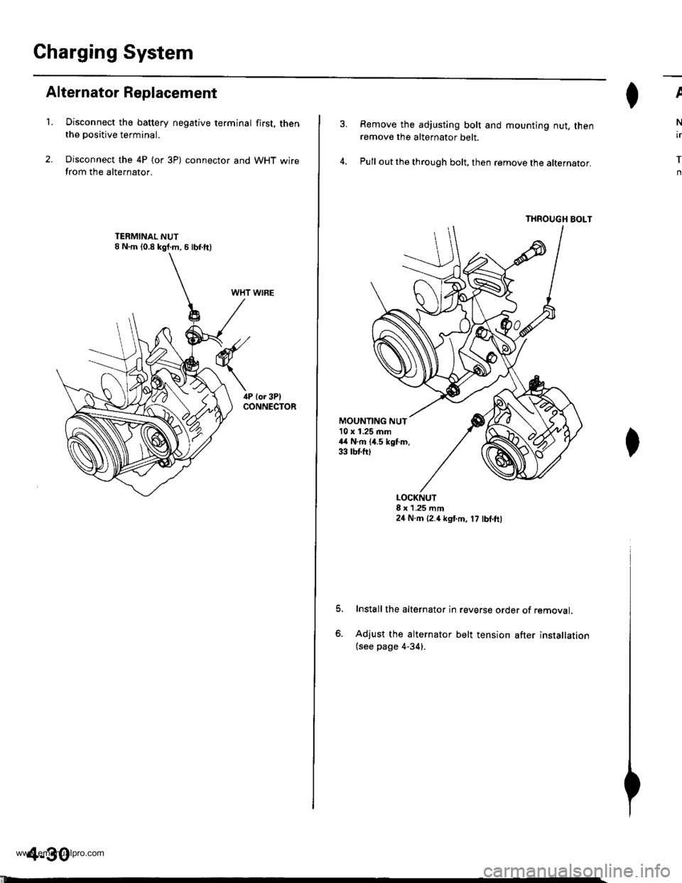
Alternator Replacement
't.Disconnect the battery negative terminal first, thenthe positive terminal.
Disconnect the 4P (or 3P) connector and WHT wirefrom the alternator.
WHT WIRE
4-30
'll
Remove the adjusting bolt and mounting nut, thenremove the alternator belt.
Pull out the through bolt, then remove the alternator.
THROUGH BOLT
ll^I}v
N
ir
T
n
MOUNTING NUT10 x 1.25 mm44 N.m 14.5 kgf.m.33 tbtfttt
o.
LOCKNUT8 x 1 .25 mm24 N.m (2.4 kgt m, 17 lbl.ft,
Install the alternator in reverse order of removal.
Adjust the alternator belt tension after installation(see page 4-34).
www.emanualpro.com
Page 84 of 1395
Charging System
Alternator Belt Inspection and Adjustment
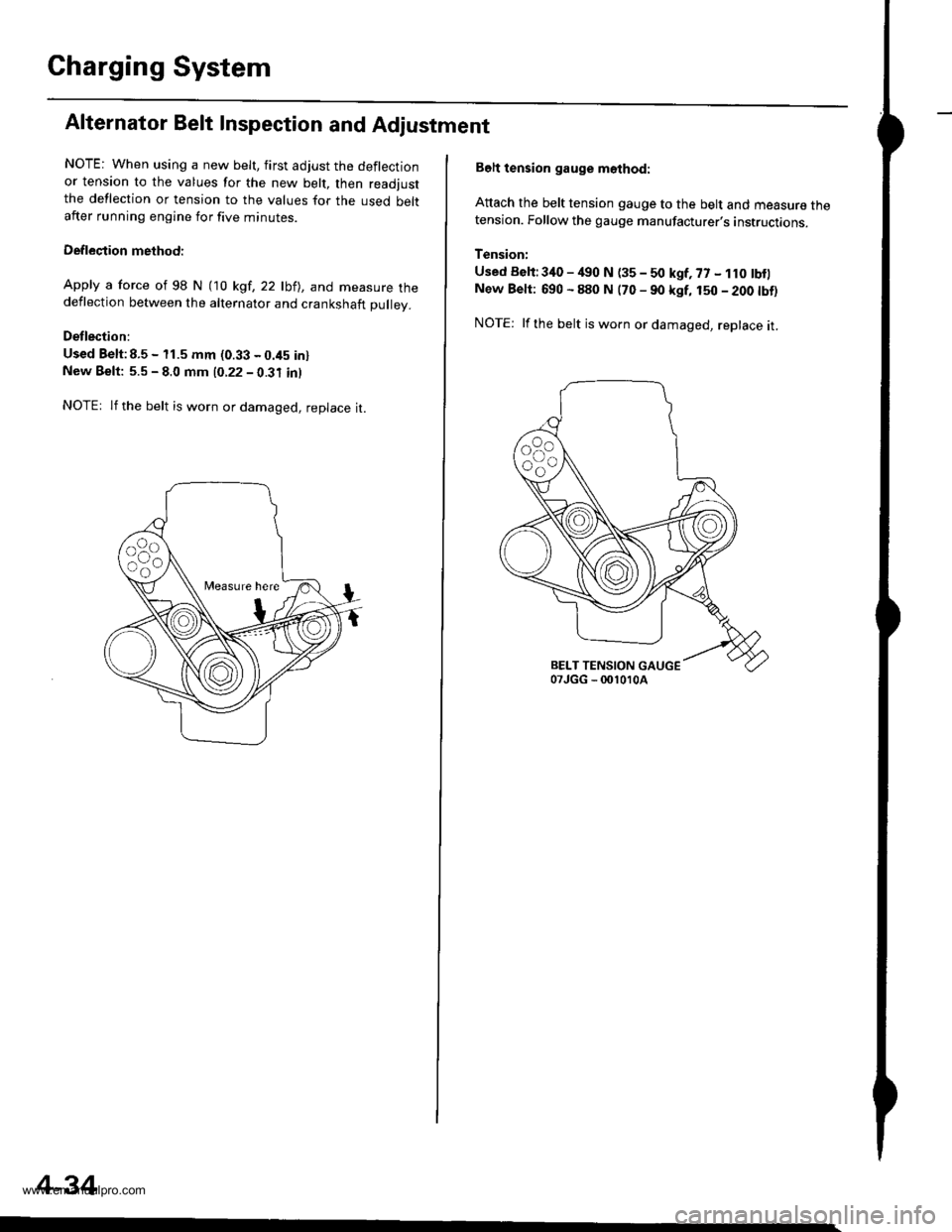
NOTE: When using a new belt, first adjust the deflectionor tension to the values for the new belt, then readjustthe deflection or tension to the values for the used beltafter running engine for five minutes.
Deflection methodi
Apply a force of 98 N (10 kgt,22lbll, and measure thedeflection between the alternator and crankshaft pulley.
Detlection:
Used Belt:8.5 - 11.5 mm (0.33 - 0.45 inlNew Beft: 5.5 - 8.0 mm 10.22 - 0.31 inl
NOTEr lf the belt is worn or damaged, replace it.
Measure here
4-34
Belt tension gauge m6thod:
Attach the belt tension gauge to the belt and measure thetension. Follow the gauge manufacturer's instructions.
Tension:
Used Belt:340 - /€0 N (35 - 50 kgf, 77 - 1r0 tbf)New Belt: 690 - 880 N (70 - 90 kgf, 150 - 200 tbt)
NOTE: lfthe belt is worn or damaged, replace it.
www.emanualpro.com
Page 550 of 1395
Description
Hydraulic Flow (cont'dl
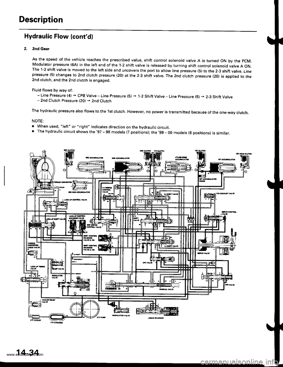
2nd Gsar
As the speed of the vehicle reaches the prescribed value. shift control solenoid valve A is turned ON by the pCM.Modulator pressure (6A) in the left end of the 1-2 shift valve is released by turning shift control solenoid valve A ON.The 1-2 shift valve is moved to the left side and uncovers the port to allow line pressure (5) to the 2-3 shift vatve. Linepressure (5) changes to 2nd clutch pressure (20) at the 2-3 shift valve, The 2nd clutch pressure {20) is appli€d to the2nd clutch. and the 2nd clutch is engaged.
Fluid flows by way of:- Line Pressure (4) + CPB Valve - Line Pressure (5) * 1-2 Shift Valve - Line pressure (S) * 2-3 Shift Valve- 2nd Clutch Pressure (20) - 2nd Clutch
The hydraulic pressure also flows to the lst clutch. However, no power is transmitted because of the one-wav ctutch.
NOTE:
. When used, "|eft" or "right" indicates direction on the hydraulic circurr_' The hydraulic circuit shows the'97 - 98 models (7 positions); the '99 - 00 models (6 positions) is similar,
14-34
www.emanualpro.com
Page 1326 of 1395
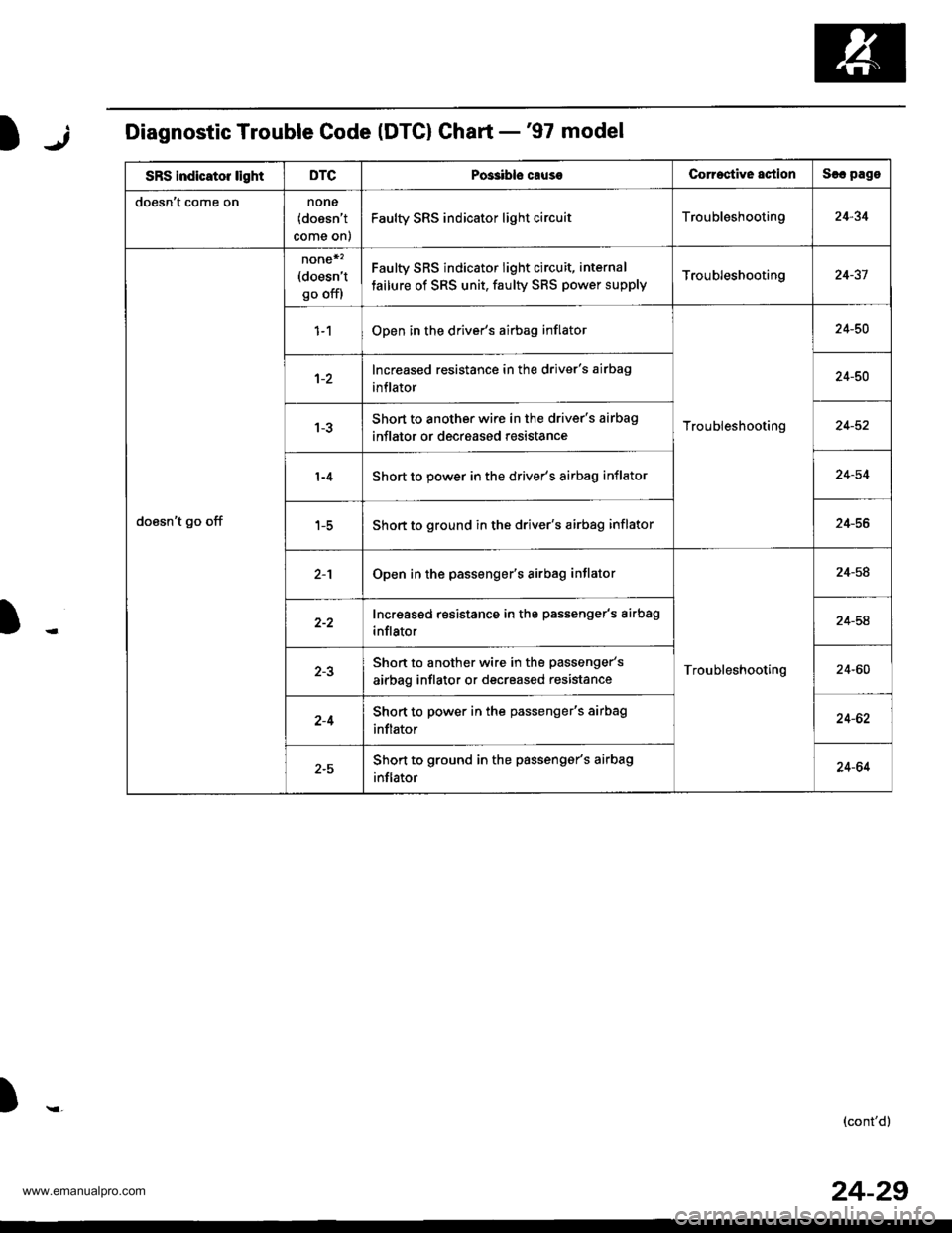
jIDiagnostic Trouble Code (DTG) Ghart -'97 model
SRS indicator lightDTCPos3ibls causeCorroctive actionSlc pago
doesn't come onnone(doesn't
come on)
Faulty SRS indicator light circuitTroubleshooting24-34
doesn't go off
none*'�(doesn't
go off)
Faulty SRS indicator light circuit, internal
tailure of SRS unit, faulty SBS power supplyTroubleshooting24-37
Open in the driver's airbag inflator
Troubleshooting
24-50
Increased resistance in the driver's airbag
inflator24-50
Short to another wire in the driver's airbag
inflator or decreased resistance24-52
Short to power in the driver's airbag inflator24-54
Short to ground in the driver's airbag inflator24-56
Open in the passenger's airbag inflator
Troubleshooting
24-58
Increased resistance in the passenger's airbag
inflator24-54
Shon to another wire in the passenger's
airbag inflator or decreased resistance24-60
2-4Short to power in the passenger's airbag
inflator24-62
2-5Shon to ground in the passengar's airbag
inflator24-64
)r,(cont'd)
24-29
www.emanualpro.com
Page 1328 of 1395
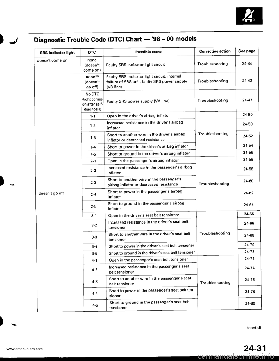
);Diagnostic Trouble Code (DTCI Chart -'98 - 00 models
SRS indicator lightDTCPossibls causeCorrectiva agtionSee page
doesn t come onnone
(doesn't
come on)
Faulty SRS indicator light circuitTroubleshooting24-34
doesn't go off
none*3
{doesn'tgo off)
No DTC
(light comes
on after self-
diagnosis)
Faulty SRS indicator light circuit. internal
failure of SRS unit, faulty SRS power supply
(VB line)
Troubleshooting24-42
Faulty SRS power supply (VA line)Troubleshooting24-47
1-1Open in the driver's airbag inflator
Troubleshooting
24-50
lncreased resistance in the driver's airbag
inflator24-50
1-3Short to another wire in the driver's airbag
inflator or decreased reslstance24-52
1-4Short to power in the driver's airbag inflator24-54
1-5Short to ground in the driver's airbag inflator24-56
2-1Open in the passenger's airbag inflator
Troubleshooting
24-54
Increased resistance in the passenger's airbag
inflator24-58
Shon to another wire in the passenger's
airbag inflator or decreased resistance24-60
2,4Short to power in the passenger's airbag
inflator24-62
Short to ground in the passenger's arrbag
inflator24-64
3-1Open in the driver's seat belt tensioner
Troubleshooting
24-66
3-2lncreased resistance in the driver's seat belt
tensroner24-66
Shon to another wire in the driver's seat belt
tensroner24-64
3-4Short to power in the driver's seat belt tensioner24-10
Short to ground in the driver's seat belt tensloner24-7 2
4-1Open in the passenger's seat belt tensioner
Troubleshooting
24-14
Increased resistance in the passenger's seat
belt tensioner24-7 4
4-3Short to another wire in the passenger's seat
belt tensioner24-7 6
4-4
4-5
Short to power in the passenger's seat belt ten-
sroner24-74
Shon to ground in the passenger's seat belt
tensroner24-AO
)-(cont'd)
24-31
www.emanualpro.com
Page 1331 of 1395
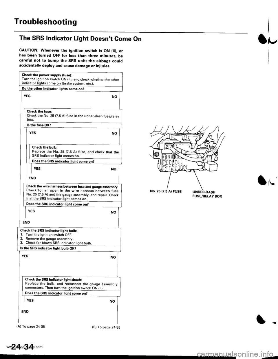
Troubleshooting
The SRS Indicator Light Doesn't Come On
CAUTION: Whenever the ignition switch is ON D, orhas been turned OFF for less than three minutes, becareful not to bump the SRS unit; the airbags couldaccidentally deploy and cause damage or iniuries.
Ch6ck the power supply (fuse):Turn the ignition switch ON {ll), and check whether the otherindicator lights come on (brake system, e(c.r.
Do the other indicator liglrts com6 on?
Check the No. 25 (7.5 A) fuse in the under-dash tuse/relayDOX.
ls the tus€ oK?
NO
Check the bulb:Replace the No.25 (7.5 A) fuse, and check that theSRS indicator light comes on.
Does the SRS indicator liqht come on?
YESNO
END
YES
Check the wire h.rnesi kwe€n fus€.nd gauge .3sembly:Check for an open in the wire harness between fuseNo. 25 (7.5 Al and the gauge assembly, and repair. Checkthat lhe SRS indicato.lighi
Does the SRS indic.tor liqht com6 on?
END
YESNO
Check the SRS indicator light bulb:1. Turn the ignition switch OFF.2. Remove the gauge assembly.3. Check lor blown SRS indicator tight bulb.
ls the SRS indicator tight bulb OK?
YESNO
Check the SRS indicator light circuit:Replace the bulb, and reconnect the gauge assemblyconneclors. Then turn the ignition switch ON {ll).
Does the SRS indicator light come on?
I YEs No
:ND
(A) To page 24-35(B) To page 24 35
24-34
lr-
lu
-J
www.emanualpro.com
Page 1332 of 1395
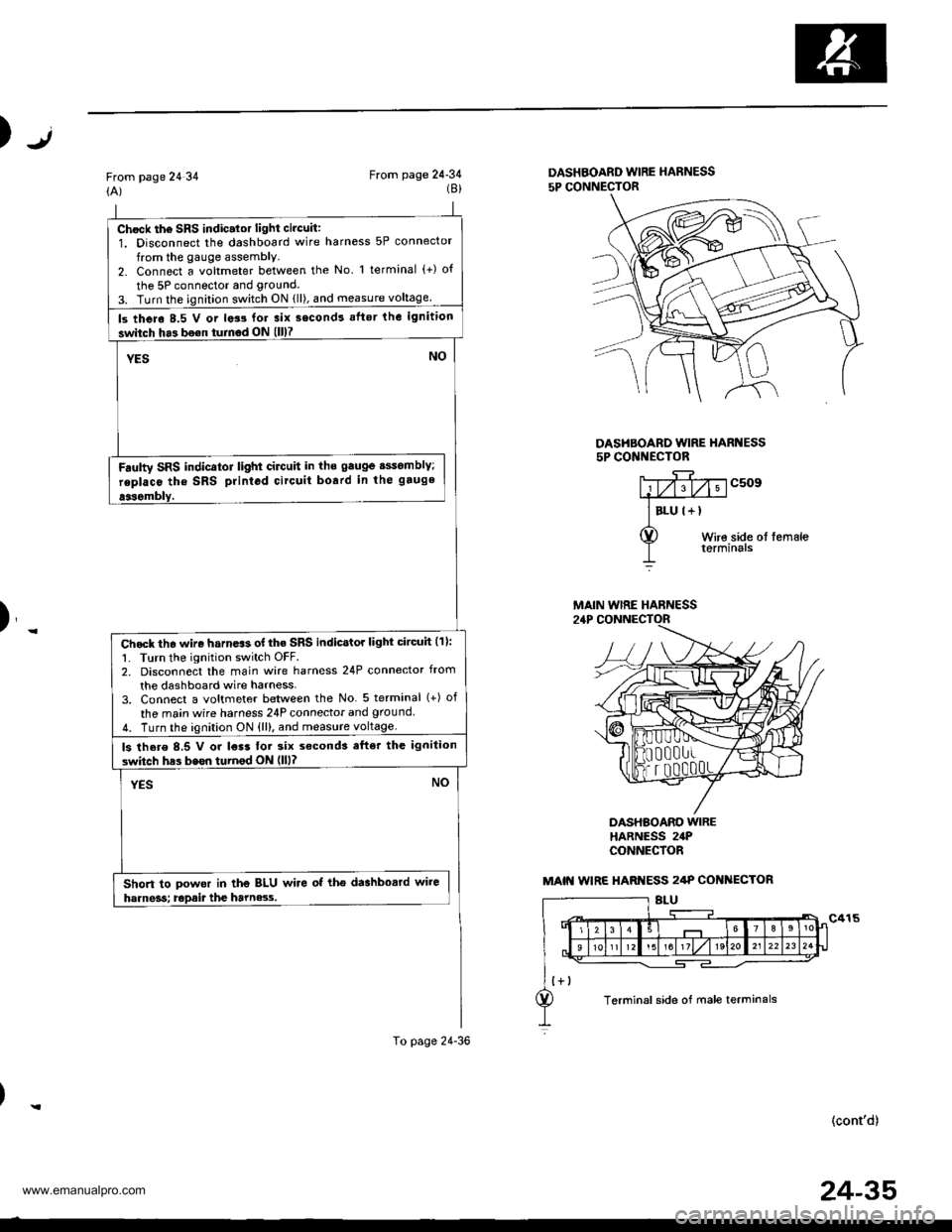
Chock th6 SRS indic.lor light circuit:1. Disconnect the dashboard wire harness 5P connector
from the gauge assembly.2. Connect a voltmeter between the No l terminal (+) o{
the 5P connector and grouncl.
3. Turn the ignition switch ON {ll), and measure voltage
ls thero 8.5 V or lats for 3ix second! aflsr the ignition
switch ha3 bo€n turnod ON (ll)7
YESNO
Fdulty SRS indicator light cilctlit in ths gauge sssomblY;
replaco tho SRS printod circuit board in the gauge
aasombly,
Chock th6 wire harn.$ of the SRS indicstor light circuh (11:
1. Turn the ignition switch OFF.2. Disconnect the main wire harness 24P connector from
the dashboard wire harness-3. Connect a voltmeter between the No 5 terminal (+) of
the ma;n wire harness 24P connecior and ground
4. Turn the ignition ON {ll), and measure voltage.
ls there 8,5 V or l€r3 tor six s€cond3 efter the ignilion
switch has bssn turnod ON llll?
YESNO
Short to powor in the BLU wire of tho dashbosrd wire
harne3s; Epait the harne3.s.
To page 24-36
Jt)
From page 24 34(A)From page 24-34(8)DASHBOARD WIRE HARNESS
5P CONNECTOR
DASHBOARD WIRE HARI{ESS5P CONI{ECTOR
c509
Wire side ol femaleterminals
)_
DASHBOARO WIREHARNESS 24PCONNECfOR
(cont'd)
MAIN WIRE HARNESS
MAIN WIRE HARI{ESS 2/tP COI{ ECTOR
Terminal side of male terminals
24-35
www.emanualpro.com