Automatic transmission replacement HONDA CR-V 1998 RD1-RD3 / 1.G Workshop Manual
[x] Cancel search | Manufacturer: HONDA, Model Year: 1998, Model line: CR-V, Model: HONDA CR-V 1998 RD1-RD3 / 1.GPages: 1395, PDF Size: 35.62 MB
Page 41 of 1395

Lubrication Points
For the details of lubrication points and type of lubricants to be applied. refer to the illustrated index and various work pro-
cedures (such as Assembly/Reassembly, Replacement, Overhaul, Installation, etc.) contained in each section.
Recomm6nded Engine OilEngine oil viscosity for ambient temperature ranges
100'F
-30 -20 .10 0 10 20 30 40'c
r1: Always use Genuine Honda Manual Transmission Fluid {MTF). Using motor oil can cause stiffer shifting because it
does not contain the orooer additives.*2: Always use Genuine Honda Premium Formula Automatic Transmission Fluid (ATF). Using a non-Honda ATF can affect
shift qualitv.+3r Always use Genuine Honda DOT 3 Brake Fluid. Using a non-Honda brake fluid can cause corrosion and decrease the
life of the system.*4: Always use Genuine Honda Power Steering Fluid. Using any other type of power steering fluid or automatic transmis-
sion fluid can caused increased wear and poor steering in cold weather.
API SERVICE LABEL
/,.*-G\
/.'z-\e\t/6AE\ll-;-1 5w-30 /---l
w
API CERTIFICATION SEAL
ffi-20 0 20
NO.LUBRICATION POINTSLUBRICANT
EngineAPI Service Grade: Use SJ "Energy Conserving" grade oil. The oilcontainer may also display the API Certitication seal shownbelow. Make sure it says "For Gasoline Engines." SAE vjscosity:See chart below.
2
TransmissionManualGenuine Honda MTF*1
AutomaticGenuine Honda Premium Formula Automatic Transmission Fluid(ATF)*'
3Rear differentialGenuine Honda CVT Fluid
4Brake line (includes ABS line)Genuine Honda DOT 3 Brake Fluid*3
5Clutch LineBrake fluid DOT 3 or DOT 4*3
6Shift lever pivots (Manual transmission)Grease with molybdenum disultide
1Release fork (Manual transmission)LJrea Grease UM264 P/N 4'1211 - PYs - 305
IPower steering gearboxSteering grease P/N 08733 - B070E
Throttle cable end {Dashboard lower panel holelSilicone grease
10l112
14
Throttle cable end (Throttle link)Brake master cylinder pushrodPedal linkageBattery terminalsFuelfill lidClutch master cylinder pushrod
Multi purpose grease
1617181920
Hood hinges and hood lockTailgate hingesHatch glass hingesDoor hinges, upper and lowerDoor opening detent
Honda White Lithium Grease
21
22
Caliper Piston seal, Dust seal,Caliper pin, PistonShilt cable and select cable {Manual transmission)Silicone grease
23Brake line ioints (Front and rear wheelhouse)Rust preventives
24Power steering systemGenuine Honda Power Steering Fluid-.
25Air conditioning compressorCompressor oil: SP 10 lP/N 38897 - P13 - A0lAH or38899-P13-A01)For Refrigerant: HFC 134a (R,134a)
3-2
www.emanualpro.com
Page 151 of 1395

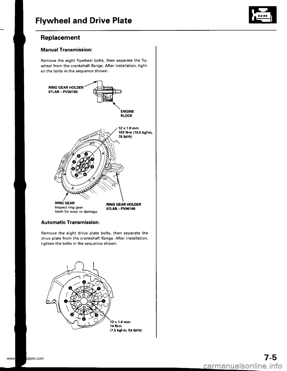
Flywheel and Drive Plate
Replacement
Manual Transmission:
Remove the eight flywheel bolts, then separate the fly-
wheel from the crankshaft flange. After installation, tight-
en the bolts in the sequence shown.
ENGINEBLOCK
12 x 1.0 mm103 N.m 110.5 kgf.m,76 lbf.ft)
Automatic Transmission:
Remove the eight drive plate bolts, then separate the
drive plate from the crankshaft flange. After installation,
tighten the bolts in the sequence shown.
RING GEARInspect ring gearteeth for wear or damage,
RI G GEAR HOTDER07LAB - PV001|X)
12 x 1.0 mm7a N.m(7.5 kgt.m,5a lbf.ftl
/ AzXi{'jA\Ao
7-5,
www.emanualpro.com
Page 517 of 1395

Automatic Transmission
Special Tools . 14'2OescriptionGeneral Operation . .... 14 3Power Flow . . .. '14_6
Electronic Control System .. .. . . .. .14_15Hydraulic Control .. 14 24Hydraulic Flow....-....... .. . .... .. .. . 14_29Lock'up Syslem .. .'t4'39Electrical SystemComponenl Locdlrons 14 45
PCM Circuil Dragram (A/T Control Svstem)'97 Model ....................... . . .. - . ... .14-46'98Model ................. . ... .. .. .1450'99 00Models.... . .... . . . 1452
PCM Terminal Voltage/Measuring ConditionsA"/T Control System-'97Model ...... ..14'48A,/T Control System -'98 00 Models . . .. . . 14 54
Troubleshooting Procedures .. ..... ... - 14_56Svmotom to comoonent CharlEiectr,cal Syslem -'97 Model . . 14 60Electrical System -'98 - OO Models . .. . . 14_62Electrical Troubleshooting ('97 Model)Troubleshooting Flowaharts .... ..... . .. . . 14_64
Electrical Troubleshooting ('98 - 00 Models)Troubleshootinq Flowclt"n" .... . ....- . .14-93ElectricalTroublesliooting('99 00Models)Troubleshootino FlowchartO/D OFF Indicator Light Does Not Come On 14 131
O/D OFF Indicator Liaht On ConstantlY . . . .1!-132O/D OFF Indicator Light Does Not Come OnEven Though O/D Switch ls Pressed . .... - 14_133
Lock up Control Solenoid Valve A,/B AssemblyTest....................-......... . .14-135Replacement . .ll_135Shifr ControlSolenoid Valve Ay'B Assembl,Test .............................. . .. 14-136
Replacement..............- . .14'136Linear Solenoid AssemblYTest.............................................. .. .... . 14_137Replacement .. . 14138Marnshaftlcountershafl Speed SensorsReplacement ...-... 14_138A/T Gear Position SwitchTest ..........................-... . .. 14-139ReplacementA/T Gear Positionlndicator.................. 14-140
Valve Eodynepair ............................... ..... . . .. - . .. ... 14 192
Assembly .................... .. 1{_193
Valve CapsDesciiption....-........................ .. ...... 14194
tnspeition ................... .. 14' 195
N4ain Valve BodyDisassembly/lnspection/Reassemblv - ...... .. 14_196
Secondarv Valve BodYDisassemblv4nspectron/ReassemblY .. . 14 198
Reoulator Valve Bodvbisassembtv,lnspiction/Reassemblv . 14199
Servo EodvDisassembly/lnspection/Reassembly ... ....14'200
Lock'uo Valve BodYDis;ssembly/lnspection/Reassembly .... . 14_201
MainshaftDisassembly/lnspection/Reassembly .. .. .. ..14'202
Inspection ....-.............. ..11_203
Sealing RingsReilaceient ...... ..... . 14'204
CountershaftDisassembly/lnspection/Reassembly .. . . . . . 11-205
Disassembly/Reassemb|y . . ........ ...... . .. 14_206Inspedron ................ . .... . 14 207
One wav ClutchDisassembly/lnspection/ReassemblY ... 11_209
Sub-shaftDisassembly/lnspection/Reassembly ... . .. . 14-210
oisassembly/Re6ssembly . . ... .-...... . . ..14-211
Sub-shaft BearingsReplacement .......14'212
Clutchllfustrated Index .......... . . .14-213
Disassembly .... .. .....14-216Reassembfy .... . .. .. . 14'218
Differentialllfustrated Index " 14-222Backlash Inspection . .... . .14'223
Bearing Repiacement .. 11-223
Differe-ntial Carrier Replacement .. .. . . . .. ..11-2?4
OifSeal Replacement. . .. 14'225
Side Clearance lnspection . . - .. ... . - ...... . .. 11'226
Transmission Housing BearingsMainshaJVCountershaft EearingsRepfacement .......14221Sub'siralt Eearing Replacement . . . . . . . . . ..11'224
Toroue Converter Housing BearingsMainshattEearing/OilSe6lReplacement . .. l4229
Countershaft Bea;ing Replacement.. .... .. ..14-230
Input Test - '97 - 98 ModelsInput Test '99 - 00 Models
Symptom to-Component ChartHydraulic System ...............
Checking
Removal ...,lllustrated Index (4WD)
Interlock SystemInterlock ControlUnit lnputTest. -..... -.. .... . - 14 144* Key Interlock Solenoid Test .- .. . . . - . . . ..... 14_146* Shift Lock Solenoid Test ..............-.-. . .. . ... .... 14 147*Shift LockSolenoidReplacement...... .. . .. .. 14 148* park pin Switch Test ......... 14 119' Park Pin Switch Replacement- '97 - 98 Models ....... 14-150* Park Pin Swirch/Over Drive (O/Di SwitchReplacemenl '99-00Models . .. 14_151over-Drive (O/D) Switch {'99 00 [4odels]Test........_..................... .......14-152Hydr.ulic System
..............._............... t4 142.................................. 14-143
Control Lever AssemblyR6placement ......,.,Reverse ldler Gear
lllustrated lndex
.......... 14-230
14 231
11-231
1nsta1|ation ..................Park StopInspeclion/AdjustmenlTransfer AssemblY.......14.232
RoadTest.............-.... ........ .StallSpeedTest ....._........................ ....... 14-159Fluid Level......_................... 14'160
Disessembly .................... 14-235Transfer Drive Gear BearingReplacementTrans{er Driven Gesf Shaft BearingReplacementTransfer Housing Roller BearingReplacementTransfer Cov€r A Bearing Outer RaceReplacementTransfer Housing Bearing Outer RaceReplacement ......-..,,,,,.....ReassemblvTransmassaonBeassembly ... -.. .... .14 250
Torque Converier/Drive Plate . .-. .... .. . ... .....14_258
Transmissionlnstatlation .................. ....... 14'259
Cooler Flushing . . ......11-261ATF Cooler HosesConnection.................. ....... 14-266I Shift LeverRemoval/lnstallation . .. 14'261
Disassemblv/Reassemblv - '97 - 98 Models . . 14_264
Disassembli/Reassemblv -'99 - 00 Models . 14-269
Over'Orive (O/D) Switch WireClearanceAdjustment. - ... . . . .. .. . 14'270
Detent Spring Replscement . . -.. ... .14'271*Shift CableAdiustment ....... 14'272
Repfacement.............. . 11'273
14 15711-237
11-237
14-238
$-234
11-23914-240
Transmigrion
Inspeclron ....., ...........Transfer AssemblyRemova1,.,,,..............,lnstallalion ........... .. ...Transmission
14 164
14-16514,167
14-169
End Cover/Transmissio . 14'174Transmission Housing .... ... .. . . .... .. 14-176Torque Converter Housingly'alve Body.. - ... -. 14 178
lllustrated lndex (2WD)End Cover/Transmissio ....... 14 180Transmission Housing . . ... . .. .... ... 14'182Torque Convener Housing/r'alve Body ......- 14-184
End CovefRemovat ...................... ....... 14'186Transmission HousingRemoval ...................... .. 14_188Torque Convener HousingA/alve BodYRemovat ................-..... .-..... 14-190
www.emanualpro.com
Page 860 of 1395

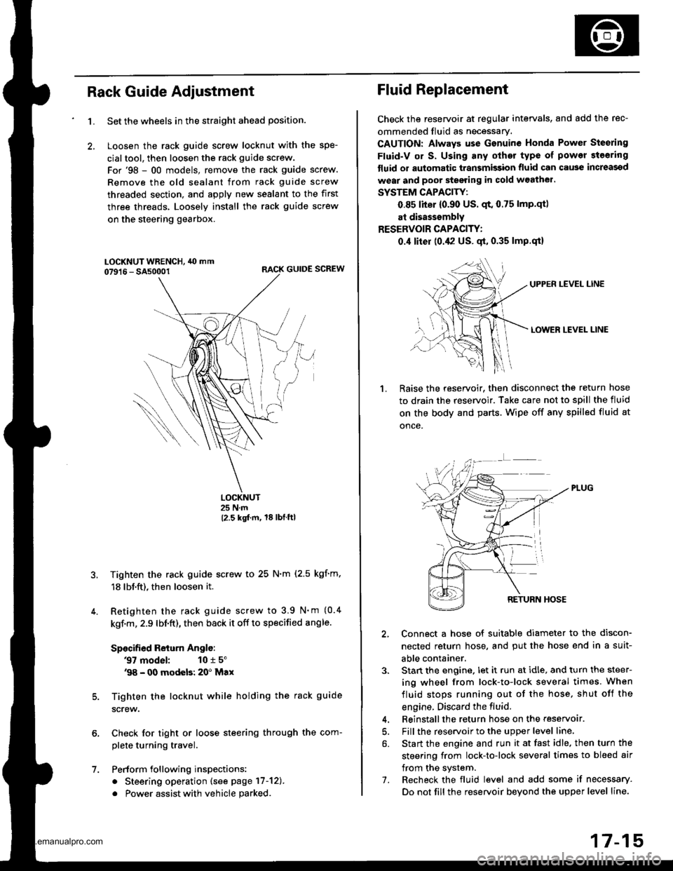
Rack Guide Adjustment
1.
6.
7.
5.
4.
Set the wheels in the straight ahead position.
Loosen the rack guide screw locknut with the spe-
cialtool, then loosen the rack guide screw.
For'98 - 00 models, remove the rack guide screw.
Remove the old sealant from rack guide screw
threaded section, and apply new sealant to the first
three threads. Loosely install the rack guide screw
on the steering gearbox.
RACK GUIDE SCREW
LOCKNUT25 N.m
12.5 kgt m, 18lbtftl
Tighten the rack guide screw to 25 N.m (2.5 kgf'm,
18 lbf.ft), then loosen it.
Retighten the rack guide screw to 3.9 N'm (0.4
kgf.m, 2.9 lbf.ft), then back it off to specified angle.
Specified Return Anglo:
37 model: 10 r 5"'98 - 00 modeb: 20' Max
Tighten the locknut while holding the rack guide
screw.
Check for tight or loose steering through the com-
plete turning travel.
Perform following inspections:
. Steering operation (see page 17-12).
. Power assist with vehicle parked
Fluid Replacement
Check the reseryoir at regular intervals, and add the rec-
ommended fluid as necessary.
CAUTION: Always use Gsnuine Honda Power Steering
Fluid-V or S. Using any other type of power steering
tluid or automatic transmission fluid can cause increassd
wear and poor steering in cold w3athel.
SYSTEM CAPACITY:
0.85 liter {0.90 US. qt. 0.75 lmp.qtl
at disasssmbly
RESERVOIR CAPACITY:
0.,1 liter (0.42 US. gt, 0.35 lmp.qi)
UPPEN LEVEL LINE
LOWER LEVEL LINE
1.Raise the reservoir. then disconnect the return hose
to drain the reservoir. Take care not to spill the fluid
on the body and parts. Wipe off any spilled fluid at
once.
2, Connect a hose of suitable diameter to the discon-
nected return hose, and put the hose end in a suit-
able container.
3. Stan the engine. let it run at idle, and turn the steer-
ing wheel from lock-to-lock several times. When
fluid stops running out of the hose, shut off the
engine. Discard the fluid.
4. Beinstallthe return hose on the reservoar.
5. Fill the reservoir to the upper level line,
6. Start the engine and run it at fast idle. then turn the
steering from lock-to-lock several times to bleed air
from the system.
7. Recheck the fluid level and add some if necessary.
Do not fill the reservoir beyond the upper level line.
www.emanualpro.com