Rear drum HONDA CR-V 1998 RD1-RD3 / 1.G Workshop Manual
[x] Cancel search | Manufacturer: HONDA, Model Year: 1998, Model line: CR-V, Model: HONDA CR-V 1998 RD1-RD3 / 1.GPages: 1395, PDF Size: 35.62 MB
Page 36 of 1395
to
l
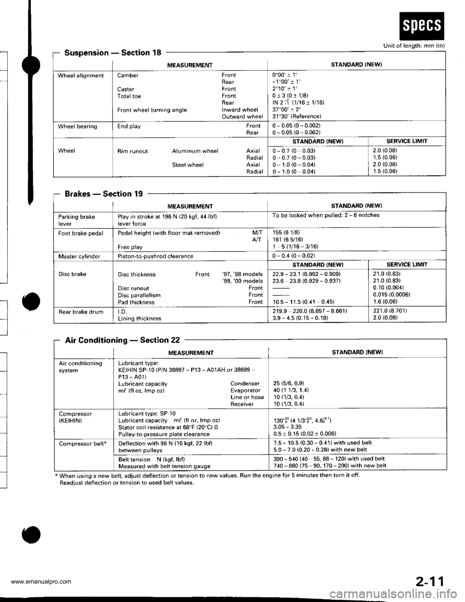
SuspensionSection 18
BrakesSec'tion 19
Air ConditioningSection 22
* When using a new belt, adjust deflection or tension to new values. Run the engine for 5 minutes then turn it off.
Readjust deflection or tension to used belt values.
o
Unit of length: mm {in)
MEASUREMENTSTANDARD {NEW)
WheelalignmentCamber FrontRearCaster FrontTotaltoe FrontnearFront wheel turning angle Inward wheelOutward wheel
0"00' 1 1'- 1"00' 1 1'2"10' ! 1"0J3(011/8)rN 2 ri (1/161 1/r6)37"00' ! 231'30'(Referencei
Wheel bearingEnd playFrontRear0 - 0.05 {0- 0.002}0 - 0.05 (0 0.002i
Rim runout Aluminum wheel AxialBadialSteelwheel AxialRadial
STANOARD (NEW)SERVICE LIMIT
0 - 0.7 (0 0.03)0,0.7 (0 - 0.03)0 1.0 (0 - 0.04)0 - 1.0 {0 - 0.04)
2.0 (0.08)'r.5 {0.06)2.0 {0.08)1.s (0.06)
MEASUREMENTSTANDARD INEWI
Parking brakeleverPlay in stroke at 196 N (20 kgf,44lbf)lever force
To be locked when Dulled: 2 - 6 notches
Foot brake pedalPedal height (with tloor mat removed)
Free playNT
155 (6 1/8)161 (6 5/16)1 5 (1/16 - 3/16)
Master cylinderPiston-to-pushrod clearance0 - 0.4 (0- 0.02)
Disc brakeDisc thickness Front '97, '98 models'99, '00 modelsDisc runoutDisc parallelismPad thickness
FrontFrontFront
STANDARD {NEW'SERVICE LIMIT
22.9 - 23.1 (0.902 - 0.909)23.6 23.8 (0.929 - 0.937)
10.5 - 11.5 (0.4'�t 0.45)
21.0 (0.83)
21.0 (0.83)
0.10 {0.004)0.015 (0.0006)
1.6 (0.06)
Rear brake drumLD.Lining thickness
2r9.9 220.0 (8.657 - 8.661)3.9 - 4.5 (0.15 - 0.18)221.O 8.70112.0 (0.08)
MEASUREMENTSTANDARD {NEWI
Air conditioningLubricant type:KEIHIN SP 10 (P/N 38897 - Pl3 - A01AH or 38899 -
Pl3 - A01)Lubricant capacity Condensermf {floz, lmp oz) EvaporatorLine or hoseReceiver
25 (5/6,0.9)
40 {1 1/3, 1.4)10 {1/3,0.4)10(.]/3,0.4)
Compressor(KEIHIN)Lubricant type: SP 10Lubricant capacity ml ({l 02, lmp oz}Stator coil resistance at 68'F (20"C) OPulley-to-pressuae plate clearance
130'3'{4 1fi'3o, 4.6;"}3.05 - 3.350.51 0.15 (0.02 1 0.006)
Compressor belt*Deflection with 98 N (10 kgl,22lblibetween pulleys7.5 - 10.5 {0.30 - 0.41) with used belt5.0 - 7.0 (0.20 - 0.28) with new belt
Belt tension N (kgf, lbf)Measured with belt tension gauge390 - 540 (40 55,88-120)withusedbelt740 - 880 {75 90, 170 - 200) with new belt
2-11
www.emanualpro.com
Page 38 of 1395

--
-
METRICITEMENGLISHNOTES
AIR CONDITIONINGCooling capacity3,520 Kcal/h j 14,000 BTU/h
Compressor Type/manutacturerNo. of cylinderCaPacityMax. speedLubricant capacityLubricant type
Scroll/KElHlN
85.7 mf/rev | 5.23 cu'in/rev10,000 rpm130mf 1 algIlozsP-10
Condenser TypeCorrugated fin
Evaporator TypeCorrugated fin
Blower TypeMotor inputSpeed controlMax. capacity
Sirocco fan200 w 112 v4-Speeo440 m3/h 15,500 cu fvh
Temperature control
Compressor clutch TypePower consumptionDry, single plate, poly-V-belt drive40 W max./12 VAt 68'F (20 C)
Befrigerant TypeOuantity
HFC-134a 1R-134a)zoo o' g 24j an oz
STEERING SYSTEMTypeOverall ratioTurns, lock to lockSteering wheel diameter
Power assisted, rack and pinion
SUSPENSIONType Front
Bear
Shock absorber Front and Rear
Independent double wishbone, coil springwith stabilizerIndependent double wishbone, coil springwith stabilizerTelescopic, hydraulic nitrogen gas tilled
WHEEL ALIGNMENTCamber
CasterTotaltoe
FronthearFrontFrontRear0inln 1/16 in0mmln2mm
0'- r"00'2.10'�
BRAKE SYSTEMTvpe
Pad surface areaLining surface areaParking brake
Front
RearFrontRearTvpe
Power-assisted selt-ad,ustingventilated discPower assisted self-adiusting drum49 cm, x 2 7.6 sq-in x 273 cm, x2 11.3 sq-in x 2Mechanical actuating, rear two wheel brakes
Drum brake
TIRESize and pressureSee tire inlormation label.
ELECTRICALBafteryStarterAlternator
In under-dash fuse/relay boxIn under hood fuse/relay box
In underhood ABS fuse/relay boxHeadlightsFront turn signal lights
Front parking lightsFront side marker lightsRear side marker lightsRear turn signal lightsErake/parking lightsBack-up lightsCeiling lights {fronvrear)License plate lightSpotlightsHigh mount brake lightlgnition key lightAshtray lightGauge lightsIndicator lightslllLrmination and pilot IightsHeater illumination lights
12 V, 36 AH/s HR12V 1.0, 1.1 kW12V 100A
7.5 A, 10 A, 15 A, 20 A7.5 A, 10 A, 15 A, 20 A, 30 A, 40 A'100 A7.5 4,20 A. 40 A12V 60/55 W12 V- 21 W ('97 model),12 V - 27 W ('98-00 models)12V 5 W {'97 model),3 CP ('98 - 00 models)12V-8W12 V,3 CP12V-21W12 V 2115 W12V 21 CP (18 W)12V-8W12V-8W12V-5W12V -21W
12 V- 1.4 W12V 1.4 W12 V 1.4 W,3 W,3.4 W12V-0.84W, 1.12 W, 1.4 W,3 W, LED12 V - 0.84 W, 1.4 W, LED12 V,1.4 W
2-13
www.emanualpro.com
Page 520 of 1395
Description
General Operation (cont'dl
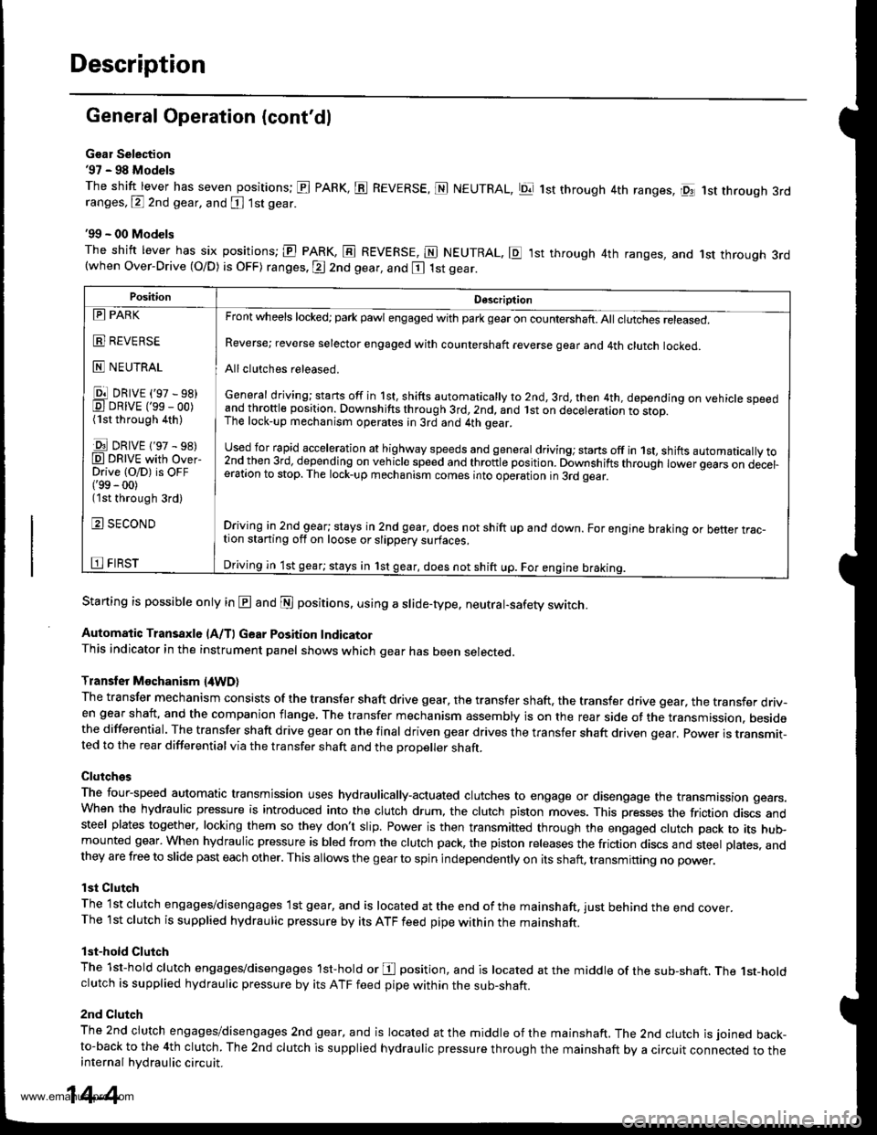
Gsar Selection'97 - 98 Models
The shift lever has seven positions; El PARK, ts REVERSE, N NEUTRAL, Ell 1st through 4th ranges, lpq 1st th.ough 3rdranges, P 2nd gear, and [ 1st gear
'99 - 00 Models
The shitt lever has six positions; El PARK, E REVERSE, E NEUTRAL. E ,lst through 4th ranges, and 1st through 3rd(when Over-Drive (O/D) is OFF) ranges. @ 2nd gear, and E 1st gear.
Starting is possible only in @ and @ positions. using a slide-type. neutral-safety switch.
Automatic Transaxle (A/T) Gear Position IndicatorThis indicator in the instrument panel shows which gear has been selected.
Transler Mochanism {4WD}
The transfer mechanism consists of the transfer shaft drive gear. the transfer shaft. the transfer drive gear, the transfer driv-en gear shaft, and the companion flange, The transfer mechanism assembly is on the rear side ot the transmission. besidethe differential. The transfer shaft drive gear on the final driven gear drives the transfer shaft driven qear. power is transmit-ted to the rear differential via the transfer shaft and the Drooeller shaft.
Clutches
The four-speed automatic transmission uses hydraulically-actuated clutches to engage or disengage the transmission gears.When the hydraulic pressure is introduced into the clutch drum, the clutch piston moves. This presses the friction discs andsteel plates together, locking them so they don't slip. Power is then transmifted through the engaged clutch pack to its hu$mounted gear. When hydraulic pressure is bled from the clutch pack, the piston releases the friction discs and steel plates, andthey are free to slide past each other. This allows the gearto spin independently on its shaft, transmitting no power.
lst Clutch
The 1st clutch engages/disengages lst gear, and is located at the end ofthe mainshaft, just behind the end cover.The 1st clutch is supplied hydraulic pressure by its ATF feed pipe within the mainshaft.
lst-hold Clutch
The 1st-hold clutch engages/disengages 1st-hold or E position, and is located at the middle of the sub-shaft. The 1st-holdclutch is supplied hydraulic pressure by its ATF feed pipe within the sub-shaft.
2nd Clutch
The znd ciutch engages/disengages 2nd gear, and is located at the middle of the mainshaft. The 2nd clutch is joined back-to-back to the 4th clutch. The 2nd clutch is supplied hydraulic pressure through the mainshaft by a circuit connected to theinternal hydraulic circuit.
PositionDescription
Reverse; reverse selector engaged with countershaft reverse gear and 4th clutch locked.
Allclutches released.
General driving; starts off in 1st, shifts automatically to 2nd, 3rd, then 4th, depending on vehicle speedand throftle position. Downshifts through 3rd,2nd, and lst on deceleration to stop.The lock-up mechanism operates;n 3rd and 4th gear.
used for rapid €cceleration at highway speeds and general driving; stans off in 1st, shifts automatically to2nd_then 3rd, dejending on vehicle speed and throttle position. Downshifts through lower gears on decel-eration to stop. The lock-up mechanism comes into operation in 3rd gear.
Driving in 2nd_gear; stays in 2nd gear, does not shift up and down. For engine braking or better trac_tion starting off on loose or slippery surfaces.
Driving in 1st gear; stays in 1st gear, does not shift up. For engine braking.
tll PARK
t!!l l|EvEn>E
E NEUTRAL
Ell DRrvE ('97 - sB)E DRrvE ('ss - oo)(1st through 4th )
E DRrvE {'97 - s8)O DRTVE with over-Drive (O/D) is OFF('99 - 00)(1st through 3rd)
E SECOND
E FIRST
14-4
www.emanualpro.com
Page 905 of 1395
Wheel/Hub lnspection
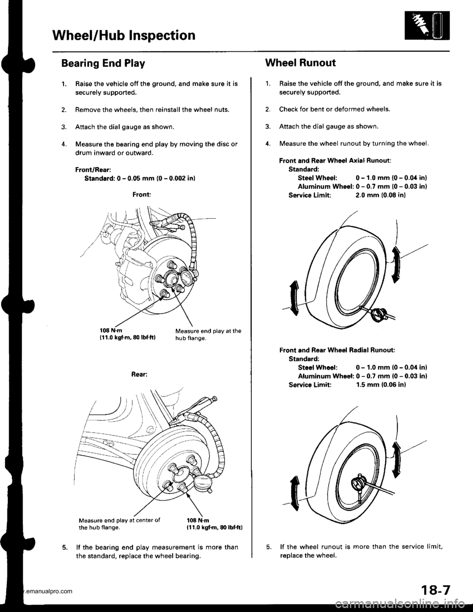
Bearing End Play
1.Raise the vehicle off the ground, and make sure it is
securely supported.
Remove the wheels, then reinstall the wheel nuts.
Attach the dial gauge as shown.
Measure the bearing end play by moving the disc or
drum inward or outward.
Front/Rear;
Standard: 0 - 0.05 mm (0 - 0.002 in)
Measure end play at thehub flange.
Rear:
Measure end play at center ofthe hub flange.108 N.m{11.0 kgf.m, q} lbf.ftl
It the bearing end play measurement is more than
the standard, replace the wheel bearing.
1.
Wheel Runout
Raise the vehicle off the ground, and make sure it is
securely supported,
Check for bent or deformed wheels.
Attach the dial gauge as shown.
Measure the wheel runout by turning the wheel.
Front and Rear Whoel Axial Runout:
Standard:
Steel Wheel: 0 - 1.0 mm {0 - 0.0i[ in]
Aluminum Wheel: 0 - 0.7 mm l0 - 0.03 in)
Service Limit:2.0 mm 10.08 inl
Front and Rear Wheel Radial Runout:
Standard:
Steel Whoal: 0 - 1.0 mm (0 - 0.04 inl
Aluminum Whoel: 0 - 0.7 mm {0 - 0.03 in}
Servics Limit:1.5 mm (0.06 inl
lf the wheel runout is more than the service limit,
reolace the wheel.
18-7
www.emanualpro.com
Page 918 of 1395
Rear Suspension
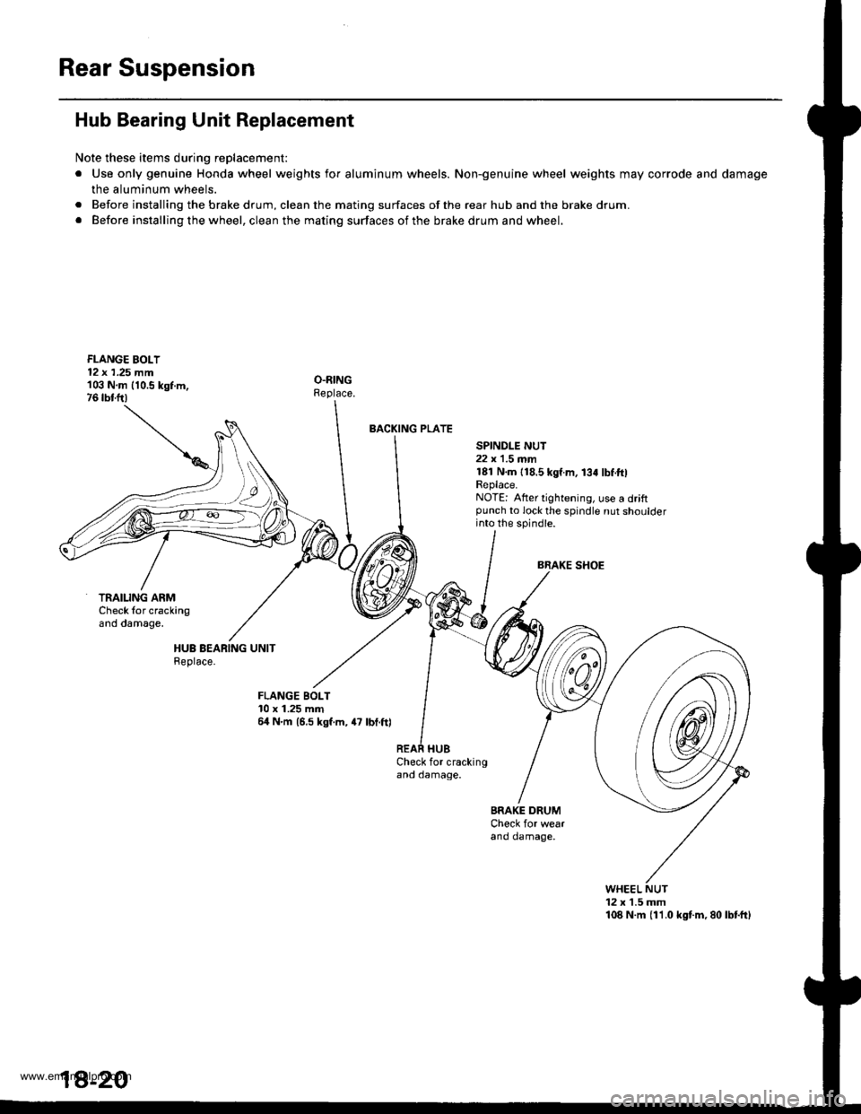
Hub Bearing Unit Replacement
Note these items during replacement:
. Use only genuine Honda wheel weights for aluminum wheels. Non-genuine wheel weights may corrode and damage
the aluminum wheels.
. Before installing the brake drum, clean the mating surfaces of the rear hub and the brake drum.
. Before installing the wheel, clean the mating surfaces of the brake drum and wheel.
FLANGE BOLI12 x 1,25 mm103 N.m 110.5 kgf.m,76 tbtfr)
BACKING PLATE
SPINDI-E NUT22 x'1.5 mm181 N.m {18.5 kgf.m, 134 lbf.ftlReplace.NOTE: Alter tightening, use a driftpunch to lock the spindle nut shoulderinto the spindle.
BRAKE SHOE
TRAILING ARMCheck {or crackingano oamage.
FLANGE BOLT10 x 1.25 mm64 N'm 16.5 kgf.m, 4? lbt.ft)
Check for crackingano oamage.
BRAKE DRUMCheck for wearano oamage,
WHEEL NUT12 x 1.5 mm108 N.m {11.0 kgt m,80lbtftl
1A-20
www.emanualpro.com
Page 919 of 1395
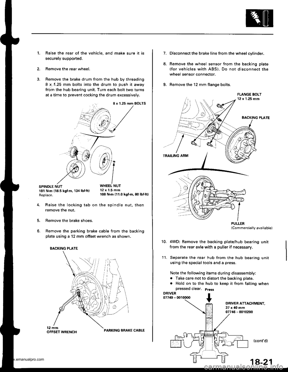
Raise the rear of the vehicle, and make sure it is
securely supponed.
Remove the rear wheel.
Remove the brake drum from the hub by threading
8 x,r.25 mm bolts into the drum to push it away
from the hub bearing unit. Turn each bolt two turns
at a time to prevent cocking the drum excessively.
SPINDLE NUTWHEEL NUT
r81 N.m t18.5 kgt m, 134 lbt'ftl 12 x 1.5 mm
Replace. 108 N m 111.0 kgf'm, 80 lbf ftl
't.
4.
8 x 1.25 mm BOLTS
i+/3 /',1
"@,1 /
.'--7 J-->-
5.
6.
Raise the locking tab on the spindle nut, then
remove the nut.
Remove the brake shoes.
Remove the parking brake cable from the backing
plate using a 12 mm offset wrench as shown.
BACKING PLATE
PARKING ARAKE CABLE
1a-21
7.
6.
Disconnect the brake line from the wheel cylinder.
Remove the wheel sensor from the backing plate
(for vehicles with ABS). Do not disconnect the
wheel sensor connector.
Remove the 12 mm flange bolts.
PULLERlCommercially available)
4WD; Remove the backing plate/hub bearing unit
from the rear axle with a puller if necessary.
Separate the rear hub from the hub bearing unit
using the specialtools and a press.
Note the following items during disassembly:
. Take care not to distort the backing plate.
. Hold on to the hub to keep it from falling when
a
10.
11.
DRIVER ATTACHMENT,37 x ilo mm07746 - 0010200
(cont'd)
www.emanualpro.com
Page 925 of 1395
Brakes
Special Tools ............. 19-2
Component Locations
lndex ................ ...... 19-3
Inspection and Adlustment
Brake System Rubber Parts
and Brake Booster ..........,,,.......... 19-4
Brake Pedal ............ 19-5
Parking Brake ........ 19-6
Bleeding ................. 19'7
Brake System Indicator ................... 19-8
Front Brake Pads
Inspection and Replacement .......... 19-9
Front Brake Disc
Disc Runout Inspection ................... 19-11
Disc Thickness and
Parallelism Inspection ........,........ 19-1 1
Front Brake Caliper
Disassembly/Reassembly ............... 19-12
Master Cylinder/Brake Booster
Removal/lnstallation ....................... 19-13
Master Cylinder
Inspection/Disassembly .............. 19-14
Pushrod Clearance Adiustment ...... 19-14
Brake Booster Inspection ...,.,,,,....... 1 9-1 5
Rear Drum Brakes
Inspection .............. 19-15
Brake Shoes
Replacement ..... 19-r 8
Wheel Cylinder Replacement ......... 19-20
Brake Hoses/Lines
Inspection/Torque Specifications ... 19-21
Hose Replacement ....,...,............. ..,,, 19-22
Parking Brake Cable
Inspection and Replacement .......... 19-23
www.emanualpro.com
Page 927 of 1395
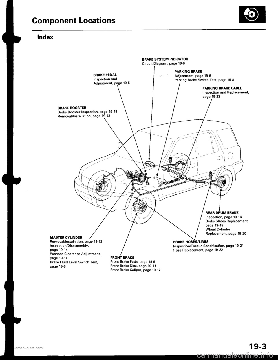
Gomponent Locations
lndex
ERAKE SYSTEM INOICATORCircuit Diagram, page't9-8
PARKING BRAKEAdjustment, page 19-6Parking Brake Switch Test, page '19-8
PARKING BRAKE CABI..EInspection and Replacement,page 19-23
BRAKE BOOSTERBrake Booster Inspection, page 19-15
Removal/lnstallation, page 19 13
MASTER CYLINDER
Inspection, pago 19-16Brake Shoes Replacement,page 19-18Wheel CylinderReplacement, page 19-20
REAR DRUM BRAKE
Removal/lnstallation, page 19-13lnspection/Disassembly.page 19-14Pushrod Clearance Adjustment,page 19 ldBrake Fluid LevelSwitch Test,page 19-8
Inspection/Torque Specification, pag€'19-21
Hose Replacement, Page 19-22
Front Brake Pads, page 19-9Front Brake Disc. page 19-11Front Brake Caliper, page 19-12
)i't ' -"''
/'"''t,'..,1 ...,. , \,,,.
i ,.'
'a.,
I
.) ..)
t ^fl)
19-3
www.emanualpro.com
Page 940 of 1395
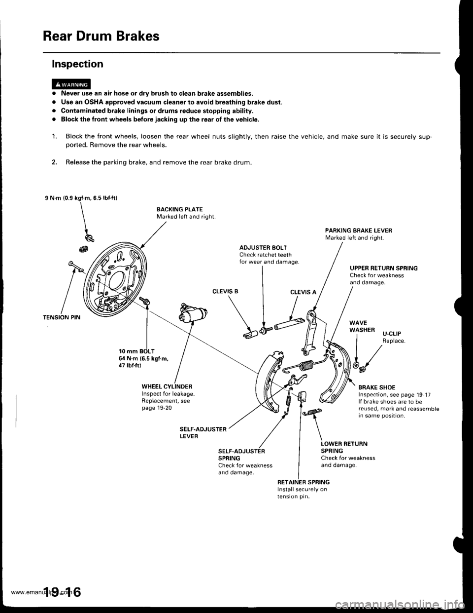
Rear Drum Brakes
Never use an air hose or dry brush to clgan brake assemblies,
Use an OSHA approved vacuum cleaner to avoid breathing brake dust.
Contaminated brake linings or drums reduce stopping ability.
Block the front wheels betore iacking up lhe rear ot the vehicle,
Block the front wheels, loosen the rear wheel nuts slightly, then raise the
poned. Remove the rear wheels.
2. Release the parking brake, and remove the rear brake drum.
I N.m {0.9rbr.ft)kgl.m,5.5
\\
\
196
@
Inspection
a
a
rl
a
1.vehicle, and make sure it is securely sup-
BACKING PLATEMarked left and right.
PARKING EBAKE I-EVERMarked left and right.
ADJUSTER BOLTCheck ratchet teethfor wear and damage.UPPER RETURN SPRINGCheck for weaknessand damage.
CLEVIS BCLEVIS A
64 N.m 16.5 kgl.m,47 lbt.ftl
\L;
SPRINGCheck for weaknessano oamage.
'l-'-' u-cllP
I Replace.
t/
6d/
BRAKE SHOEInspection, see page 19 17lf brake shoes are to bereused, mark and reassemblein same position.
WHEELInspect for leakage.Replacement, seepage 19-20
LOWER RETURNSPRINGCheck for weaknessano oamage.
RETAINER SPRINGInstall securely onlensron prn.
19-16
www.emanualpro.com
Page 942 of 1395
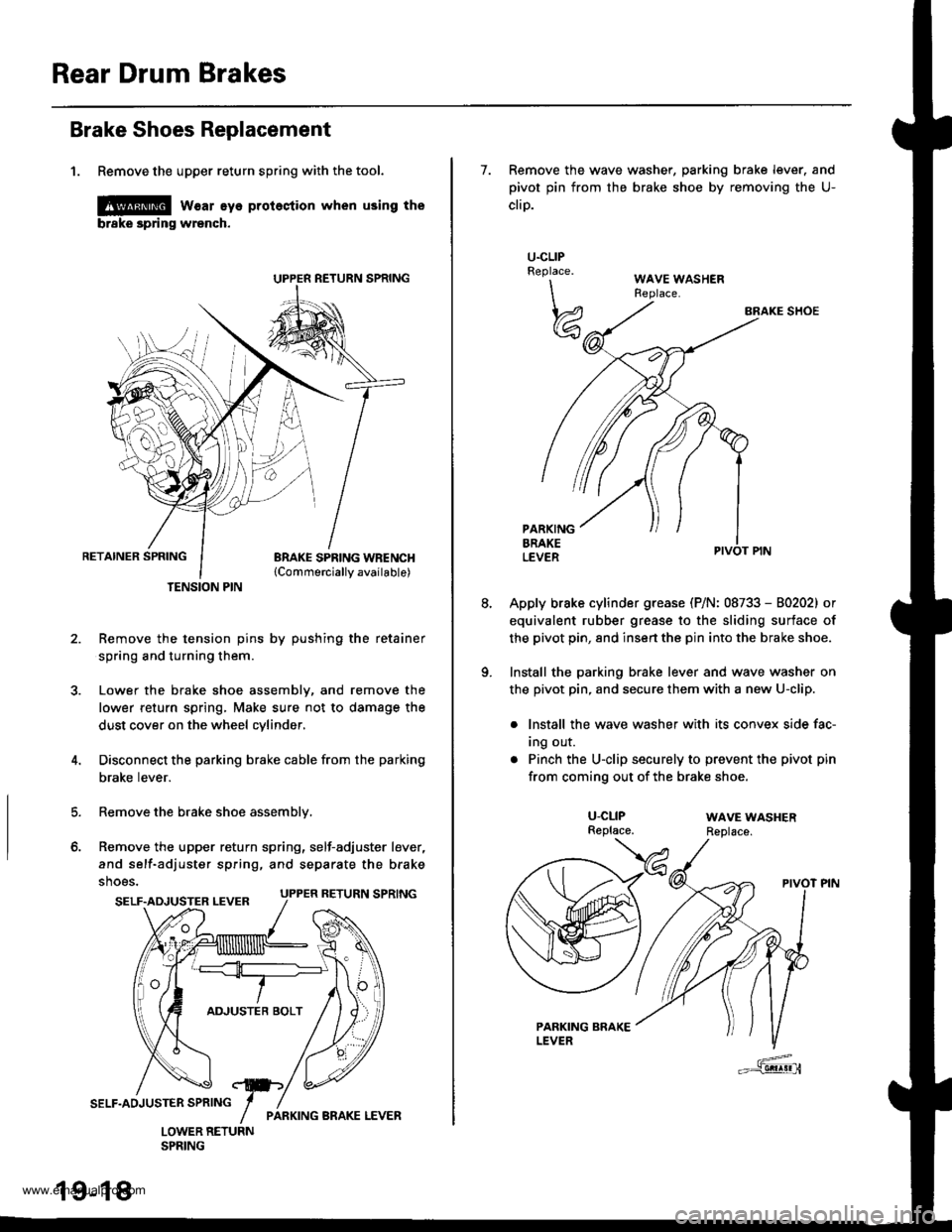
Rear Drum Brakes
Brake Shoes Replacement
1. Remove the upper return spring with the tool.
l@ w€ar eye protestion when using the
brske spring wrench.
RETAINER SPRINGBRAKE SPRING WBENCH{Commerciallv available)
Remove the tension pins by pushing the retainer
spring and turning them.
Lower the brake shoe assembly, and remove the
lower return spring, Make sure not to damage the
dust cover on the wheel cylinder,
Disconnect the parking brake cable from the parking
brake lever.
Remove the brake shoe assembly,
Remove the upper return spring, self-adjuster lever,
and self-adjuster spring, and separate the brake
shoes.
TENSION PIN
5.
o.
SELF.ADJUSTER LEVER UPPER RETURN SPRING
19-18
7. Remove the wave washer, parking brake lever. and
pivot pin from the brake shoe by removing the U-
cliD.
BRAKE SHOE
Apply brake cylinder grease (P/N: 08733 - 80202) or
equivalent rubber grease to the sliding surface of
the pivot pin, 8nd insert the pin into the brake shoe.
Install the parking brake lever and wave washer on
the pivot pin, and secure them with a new U-clip.
. lnstall the wave washer with its convex side fac-
Ing our.
. Pinch the U-clip securely to prevent the pivot pin
from coming out of the brake shoe.
U.CLIPReplace.
\\
w
U-CLIPReplace.WAVE WASHERReplace.
www.emanualpro.com