Shift solenoids HONDA CR-V 1998 RD1-RD3 / 1.G Workshop Manual
[x] Cancel search | Manufacturer: HONDA, Model Year: 1998, Model line: CR-V, Model: HONDA CR-V 1998 RD1-RD3 / 1.GPages: 1395, PDF Size: 35.62 MB
Page 540 of 1395

Description
Hydraulic Control
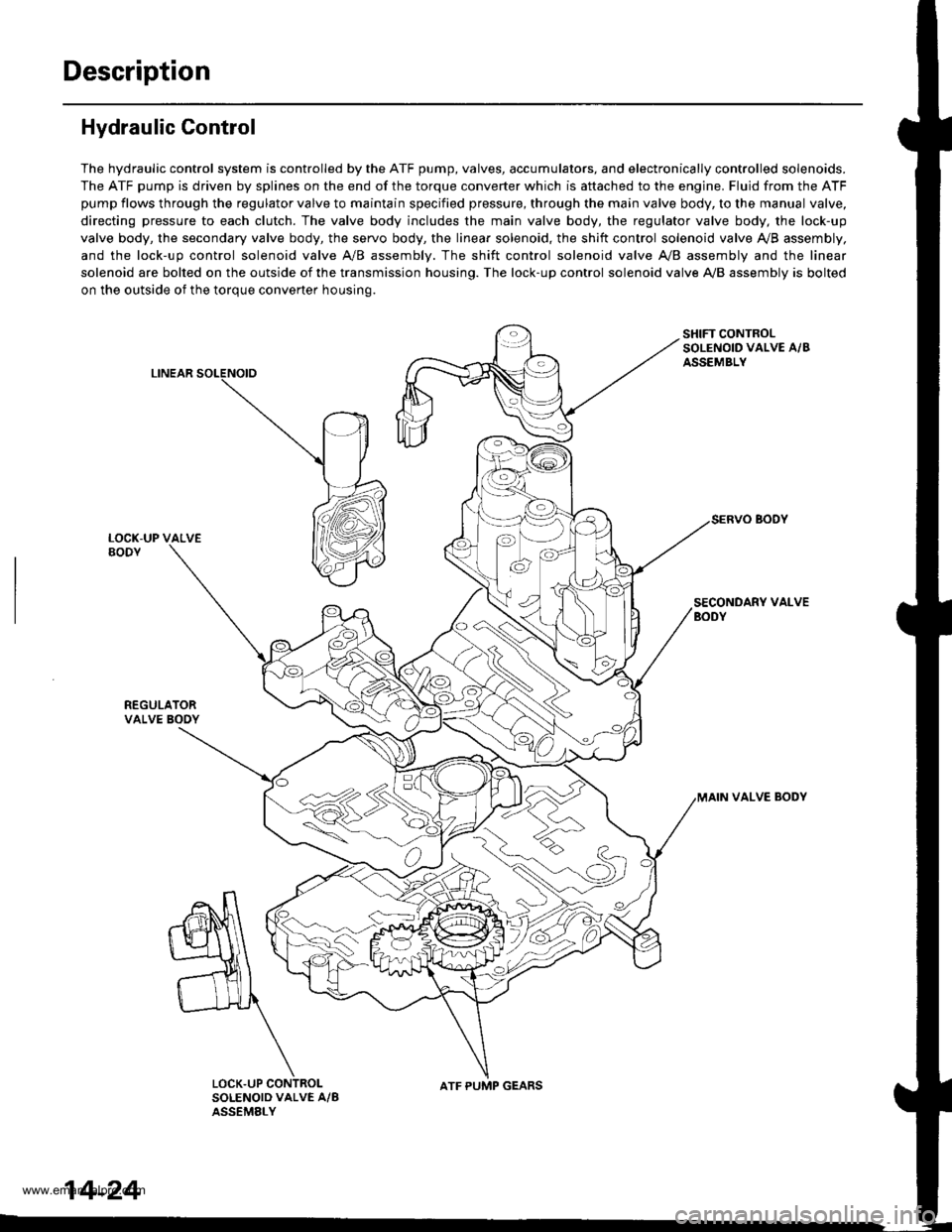
The hydraulic control system is controlled by the ATF pump, valves, accumulators, and electronically controlled solenoids.
The ATF pump is driven by splines on the end of the torque converter which is aftached to the engine. Fluid from the ATF
pump flows through the regulator valve to maintain specified pressure, through the main valve body, to the manual valve,
directing pressure to each clutch. The valve body includes the main valve body, the regulator valve body, the lock-up
valve body, the secondary valve body, the servo body, the linear solenoid, the shift control solenoid valve Ay'B assembly,
and the lock-up control solenoid valve A/B assembly. The shift control solenoid valve A,/B assembly and the linear
solenoid are bolted on the outside of the transmission housing. The lock-up control solenoid valve A,/B assembly is bolted
on the outside of the torque converter housing.
LINEAR
SHIFT CONTROLSOLENOID VALVE A/BASSEMBLY
SECONDARY VALVEBODY
REGULATORVALVE BOOY
VALVE BODY
SOLENOID VALVE A/BASSEMELY
N
ATF PUMP GEARS
14-24
www.emanualpro.com
Page 784 of 1395

Shift Lever
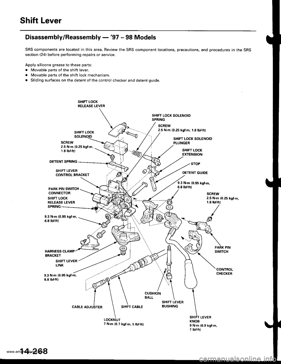
Disassembly/Reassembly -'97 - 98 Models
SRS components are located in this area. Review the SRS component locations. precautions. and procedures in the SRS
section (24) before performing repairs or service.
Apply silicone grease to these parts'
. Movable parts of the shift lever,
. Movable parts of the shift lock mechanism.
. Sliding surfaces on the detent of the control checker and detent guide.
SHIFT LOCK SOLENOIDSPRING
SCREW
SHIFT LOCK2.5 N.m {0.25 kgtm, 1.8 lbtftl
SCREW2.5 N.m {0.25 kg{.m,1.8 rbf.ft)
SHIFT LOCK SOLENOIDPLUNGER
SHIFT LOCKEXTENSION
DETENT SPFING
SHIFT LEVER
PARK PIN SWITCHCONNECTOR
SHIFT LOCKRELEASE LEVER
CONTROL BRACKET
STOP
DETENT GUIDE
9.3 N.m 10.95 kgtm,6.8 tbrft)
SPRING
9.3 N.m {0.95 kgf.m,6.8 tbf.ftl
SHIFT LEVERLINK
9.3 N.m (0.95 kgt.m,6.8 tbf.ftl
SHIFT CAALE
KNOBI N.m 10.9 kgt.m,7 rbf.ftl
14-268
7 N.m {0.7 kgf.m.5 tbt.fr}
www.emanualpro.com
Page 785 of 1395

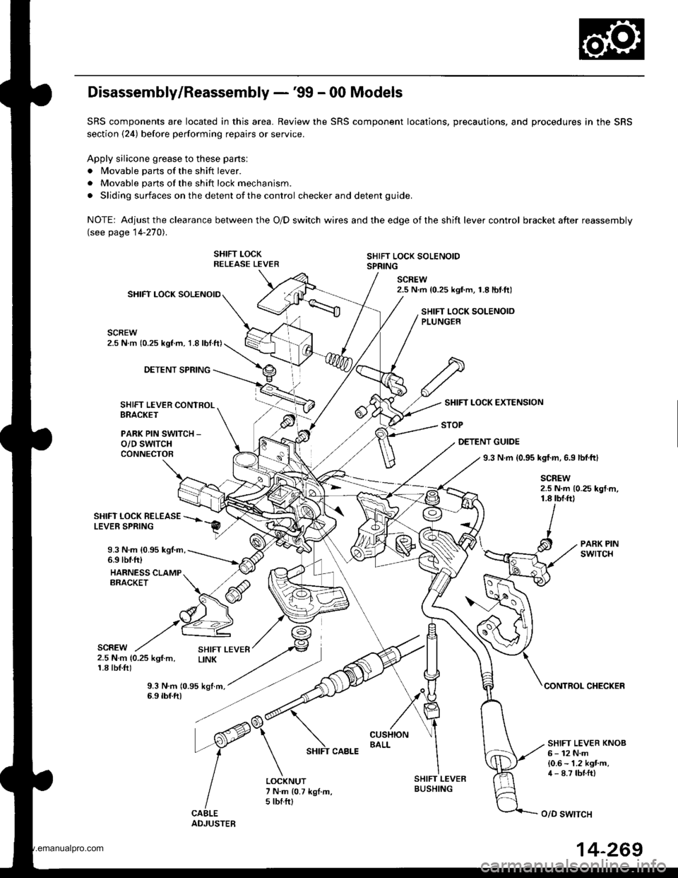
Disassembly/Reassembly -'99 - 00 Models
SRS components are located in this area. Review the SRS component locations, precautions, and procedures in the SRS
section (24) before performing repairs or service.
Apply silicone grease to these parts:
. Movable parts of the shift lever.
. Movable parts of the shift lock mechanism.
. Sliding surfaces on the detent of the control checker and detent guide.
NOTE: Adjustthe clearance between the O/D switch wires and the edge ofthe shift lever control bracket after reassembly(see page 14-270).
SHIFT LOCKRELEASE LEVERSHIFT LOCK SOLENOIDSPRING
SCREW2.5 N.m {0.25 kgf.m, 1.8lbtft)SHIFT LOCK SOLENOID
SCREW2.5 N.m (0.25 kgl.m, 1.8 lbl.ft)
SHIFT LOCK SOLENOIOPLUNGER
DETENT SPRING
SHIFT LEVER CONTROLBRACKET
PARK PIN SWITCH _
o/D swtTcHCONNECTOB
SHIFT LOCK EXTENSION
STOP
DETENT GUIDE
9.3 N.m {0.95 kgf.m, 6.9 lbl.ftl
SCREW2.5 N.m {0.25 kgt m,1.8 tbf.ftl
SHIFT LOCK BELEASELEVER SPRING
9.3 N.m {0.95 kgl.m,6.9 lbtfr)
HARNESS CLAMPERACKET
PARK PINswrTcH
SCREW2.5 N.m {0.25 kgf.m,1.8 tbl.f0
9.3 N.m 10.95 kgtm,6.9 tbf.ft)CONTROL CHECKER
SHIFT LEVER KNOB6- 12 N.m{0.6 - 1.2 kgt'm,4 - 8.7 tbnft)LOCKNUT7 N.m {0.7 kgl.m,5 tbf.ftl
SHIFT LEVERBUSHING
o/D swtTcH
14-269
www.emanualpro.com