Stabilizer HONDA CR-V 1998 RD1-RD3 / 1.G Workshop Manual
[x] Cancel search | Manufacturer: HONDA, Model Year: 1998, Model line: CR-V, Model: HONDA CR-V 1998 RD1-RD3 / 1.GPages: 1395, PDF Size: 35.62 MB
Page 38 of 1395

--
-
METRICITEMENGLISHNOTES
AIR CONDITIONINGCooling capacity3,520 Kcal/h j 14,000 BTU/h
Compressor Type/manutacturerNo. of cylinderCaPacityMax. speedLubricant capacityLubricant type
Scroll/KElHlN
85.7 mf/rev | 5.23 cu'in/rev10,000 rpm130mf 1 algIlozsP-10
Condenser TypeCorrugated fin
Evaporator TypeCorrugated fin
Blower TypeMotor inputSpeed controlMax. capacity
Sirocco fan200 w 112 v4-Speeo440 m3/h 15,500 cu fvh
Temperature control
Compressor clutch TypePower consumptionDry, single plate, poly-V-belt drive40 W max./12 VAt 68'F (20 C)
Befrigerant TypeOuantity
HFC-134a 1R-134a)zoo o' g 24j an oz
STEERING SYSTEMTypeOverall ratioTurns, lock to lockSteering wheel diameter
Power assisted, rack and pinion
SUSPENSIONType Front
Bear
Shock absorber Front and Rear
Independent double wishbone, coil springwith stabilizerIndependent double wishbone, coil springwith stabilizerTelescopic, hydraulic nitrogen gas tilled
WHEEL ALIGNMENTCamber
CasterTotaltoe
FronthearFrontFrontRear0inln 1/16 in0mmln2mm
0'- r"00'2.10'�
BRAKE SYSTEMTvpe
Pad surface areaLining surface areaParking brake
Front
RearFrontRearTvpe
Power-assisted selt-ad,ustingventilated discPower assisted self-adiusting drum49 cm, x 2 7.6 sq-in x 273 cm, x2 11.3 sq-in x 2Mechanical actuating, rear two wheel brakes
Drum brake
TIRESize and pressureSee tire inlormation label.
ELECTRICALBafteryStarterAlternator
In under-dash fuse/relay boxIn under hood fuse/relay box
In underhood ABS fuse/relay boxHeadlightsFront turn signal lights
Front parking lightsFront side marker lightsRear side marker lightsRear turn signal lightsErake/parking lightsBack-up lightsCeiling lights {fronvrear)License plate lightSpotlightsHigh mount brake lightlgnition key lightAshtray lightGauge lightsIndicator lightslllLrmination and pilot IightsHeater illumination lights
12 V, 36 AH/s HR12V 1.0, 1.1 kW12V 100A
7.5 A, 10 A, 15 A, 20 A7.5 A, 10 A, 15 A, 20 A, 30 A, 40 A'100 A7.5 4,20 A. 40 A12V 60/55 W12 V- 21 W ('97 model),12 V - 27 W ('98-00 models)12V 5 W {'97 model),3 CP ('98 - 00 models)12V-8W12 V,3 CP12V-21W12 V 2115 W12V 21 CP (18 W)12V-8W12V-8W12V-5W12V -21W
12 V- 1.4 W12V 1.4 W12 V 1.4 W,3 W,3.4 W12V-0.84W, 1.12 W, 1.4 W,3 W, LED12 V - 0.84 W, 1.4 W, LED12 V,1.4 W
2-13
www.emanualpro.com
Page 901 of 1395

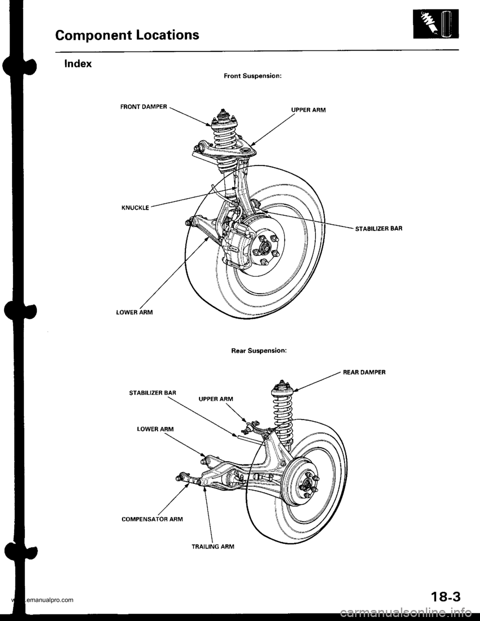
Component Locations
Front Suspension:
Rear Suspension:
STABILIZER BAR
REAR OAMPER
LOWER ARM
STABILIZER BAR
LOWER ARM
UPPER ARM
COMPENSATOB ARM
TRAILING ARM
18-3
www.emanualpro.com
Page 906 of 1395

Front Suspension
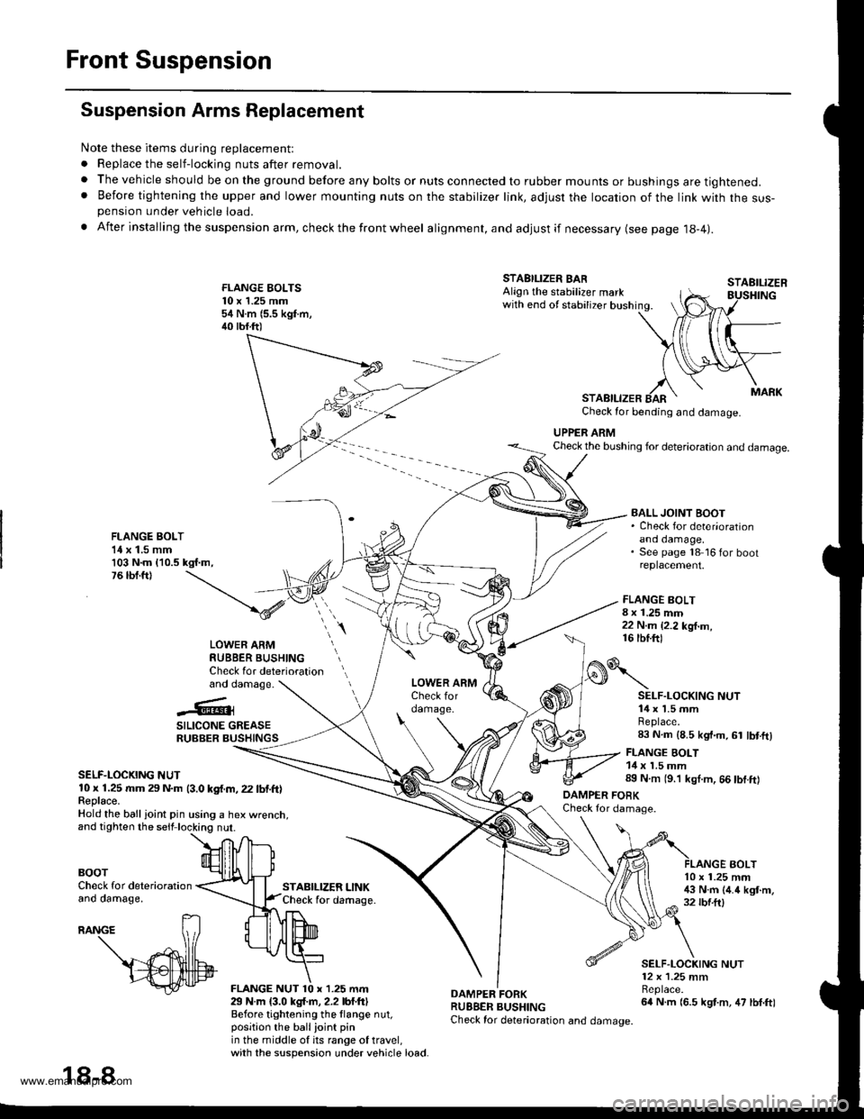
Suspension Arms Replacement
Note these items during replacement:
. Replace the self-locking nuts after removal.
. The vehicle should be on the ground before any bolts or nuts connected to rubber mounts or bushings are tightened.. Before tightening the upper and lower mounting nuts on the stabilizer link, adjusr the location of the link with the sus-pension under vehicle load.
. After insta lling the suspension arm, check the front wheel alignment, and adjust if necessary (see page 18-4|.
FLANGE EOLTS10 x 1.25 mm54 N.m (5.5 kgf.m,40 tbf.ft)
STABILIZER LINKCheck for daftage.
FLANGE BOLT8 x 1.25 mm22 N.m {2.2 kg{.m,16 tbf.ftl
STAEILIZER
AOLT
STABILIZER BARAlign the stabilizer markwith end of stabilizer bushing.
STABILIZERCheck for bending and damage.
UPPER ARMCheck the bushing for deterioration and damage.
FLANGE BOLT1{ x 1.5 mm103 N.m {10.5 kgf.m,76 tbf.ft)
BALL JOINT BOOT. Check for deter'orationano oamage,See page 18 16 for bootreplacement.
LOWER ARMRUBBER BUSHINGCheck for deteriorationand damage.
..'.{l@3
SILICONE GREASERUBBER BUSHINGS
SELF-LOCKING NUT10 x 1.25 rr|m 29 N.m (3.0 kgf.m, 22 lbf.ft)Feplace.Hold the ball ioint pin using a hex wrenct
BOOTCheck for deteriorationano oamage,
29 N.m {3.0 kgl.m, 2.2 lbf.ftlBefore tightening the llange nut,position the ballioint pinin the middle of its range of travel,with the suspension under vehicle load.
DAMPER FORKRUBBER BUSHINGCheck for deterioration and damage.
o\
DAMPER FOBKCheck for damage.
SELF.LOCKING NUT14 x 1.5 mmReplace.83 N.m (8.5 kgt.m, 61 lbt.ftl
FLANGE BOLT14 x 1.5 mm89 N.m (9.'l kgl.m, 66 tbf.ft)
10 x 1.25 mm!$ N.m (4.4 kgt.m,32 rbf.ftl
SELF.LOCKING NUT12 x 1.25 mmBeplace.64 N.m (6.5 kgt.m, 47 lbf.ft)
18-8
www.emanualpro.com
Page 917 of 1395

Rear Suspension
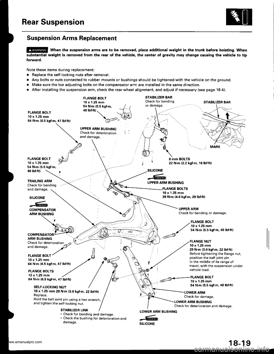
Suspension Arms Replacement
@ when the suspension arms are to be removed, plsce additional weight in lhe trunk beto.o hoisting. when
substantial weight is removed from the rear of the vehicle, the center ot grsvity m8y chango causing the vehicle to tip
forward.
Note these items during replacement:
. Replace the self-locking nuts after removal.
. Any bolts or nuts connected to rubber mounts or bushings should be tightened with the vehicle on the ground.
. Make sure the toe adjusting bolts on the compensator arm are installed in the same direction,
. After installing the suspension arm, check the rear wheel alig nment, and adjust if necessa ry (see page 18-4),
STABILIZER BARCheck for bendingor oamage.
FLANGE EOLT10 x 1.25 mm64 N.m 16.5 kgf.m,47 lbf.ft)
FLANGE BOLT10 x 1.25 mm54 N.m (5.5 kgt.m, / t40 lbf.ftt. --1 \ \A1(\
\a'v..:r
UPPER ARM BUSHINGCheck for deteriorationand damage.
il ,
FLANGE BOLT'l0 r 1.25 mm54 N.m (5.5 kgf.m,
8 mm EOLTS22 N.m {2.2 kgf.m, 16 bl.ftl
40 rbtft)
'ano oamage.
TRAILING ARMCheck for bending
stLtcoNE
-6lUPPER ARM
COMPENSATORARM BUSHING
64 N.m 16.5 kgf.m, 47 lbtftl
SELF.LOCKING NUT
BUSHING
FLANGE BOLT10 x 1.25 mm54 N.m {5.5 kgf.m, 40 lbf.ft}
FLANGE BOLTS10 x 1.25 mm39 N.m 14.0 kgf.m, 29 lbf.ft)stLtcoNE
.@iCOMPENSATORARM BUSHING
UPPER ARMCheck lor bending or damage.
FLANGE NUT10 x 1 .25 mm29 N.m {3.0 kg{.fl,22 lbf.ft}Before tightening the flange nut,position the balljoint pinin the middle of its range oftravel, with the suspension undervehicle load.
10 x 1.25 mm 29 N.m (3.0 kgl.m, 22 tbf.ft)Replace.Hold the ball ioint pin using a hex wrenct,,and tighten the self-locking nut.
STABILIZER LINK
Check tor damage.
LOWER ARM BUSHINGCheck for deterioration and damage.
. Check for bending and damage.. Check the bushing tor deterioration anddamage.
LOWEN ARM
-6ilstLrcoNE
STABILIZER 8AR
,/ FLANGE BOLT
// 10 x 1.25 mm
^/ s4 N.m 15.5 kst'm, 40 lbf ftl
BUSHING
www.emanualpro.com