Toe adjustment HONDA CR-V 1998 RD1-RD3 / 1.G Workshop Manual
[x] Cancel search | Manufacturer: HONDA, Model Year: 1998, Model line: CR-V, Model: HONDA CR-V 1998 RD1-RD3 / 1.GPages: 1395, PDF Size: 35.62 MB
Page 902 of 1395

Wheel Alignment
Caster
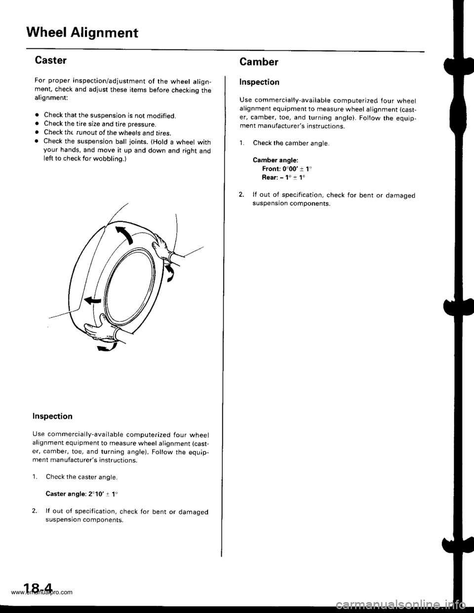
For proper inspection/adjustment of the wheel align-ment, check and adjust these items before checkinq thealignment:
. Check that the suspension is not modified.. Check the tire size and tire pressure.
. Check th( runout of the wheels and t;res,. Check the suspension ball joints. (Hold a wheel withyour hands, and move it up and down and right andleft to check for wobbling.)
Inspection
Use commercially-available computerized four wheelalignment equipment to measure wheel alignment (cast-
er, camber, toe, and turning angle). Follow the equip-ment manufacturer's instructions.
Check the caster angle.
Caster angle: 2'10':t 1"
lf out of specification, check for bent or damagedsuspension components.
1.
18-4
Camber
Inspection
Use commercially-available computerized lour wheelalagnment equipment to measure wheel alignment (cast,
er, camber, toe, and turning angle). Follow the equip,ment manufacturer's instructions.
1. Check the camber angle.
Camber angle:
Front: 0'00' 1 1"
Rear: - 1' :! 1"
2. lf out of specification, check for bent or damagedsuspensron components.
www.emanualpro.com
Page 903 of 1395

Front Toe Inspection/Adjustment
Use commercially-available computerized four wheel
alignment equipment to measure wheel alignment (caster,
camber, toe, and turning angle). Follow the equipment
manufacturer's instructions,
3.
1.Check the tire pressure.
Center the steering wheel spokes.
Check the toe with the wheels pointed straight
ahead.
Front toe-in: 0 i 3 mm {0 t 1/8 inl
- lf adjustment is required, go on to step 4.
- lf no adjustment is required, remove alignment
equipment.
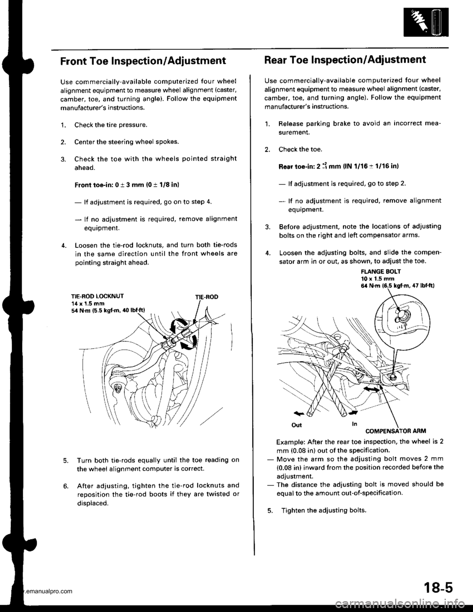
Loosen the tie-rod locknuts, and turn both tie-rods
in the same direction until the front wheels are
pointing straight ahead.
5.Turn both tie-rods equally until the toe reading on
the wheel alignment computer is correct.
After adjusting, tighten the tie-rod locknuts and
reposition the tie-rod boots if they are twisted or
displaced.
sir N m (5.5 kgJ.m, 'O lbf.ft)
Rear Toe Inspection/Adjustment
Use commercially-available computerized four wheel
alignment equipment to measure wheel alignment (caster,
camber. toe, and turning angle). Follow the equipment
manufacturer's instructions.
Release parking brake to avoid an incorrect mea-
surement.
Check the toe.
Ro8r toe-in: 2 :1 mm {lN l/16:t 1/16 in,
- lf adjustment is required, go to step 2.
- lf no adiustment is required. remove alignment
equrpmenr.
Before adjustment, note the locations of adjusting
bolts on the right and left compensator arms.
Loosen the adjusting bolts, and slide the compen-
sator arm in or out. as shown, to adiust the toe.
1.
FLANGE BOLT'10 x 1.5 mm
COMPENSATOR ARM
Example: After the rear toe inspection, the wheel is 2
mm (0.08 in) out of the specification.- Move the arm so the adjusting bolt moves 2 mm
{0.08 in) inward from the position recorded before the
adjustment.- The distance the adjusting bolt is moved should be
equal to the amount out-of-specification.
5. Tighten the adjusting bolts.
6a N.m 16.5 kgf.m, 47 lbf'ftl
18-5
www.emanualpro.com