alternator belt replacement HONDA CR-V 1998 RD1-RD3 / 1.G Workshop Manual
[x] Cancel search | Manufacturer: HONDA, Model Year: 1998, Model line: CR-V, Model: HONDA CR-V 1998 RD1-RD3 / 1.GPages: 1395, PDF Size: 35.62 MB
Page 51 of 1395

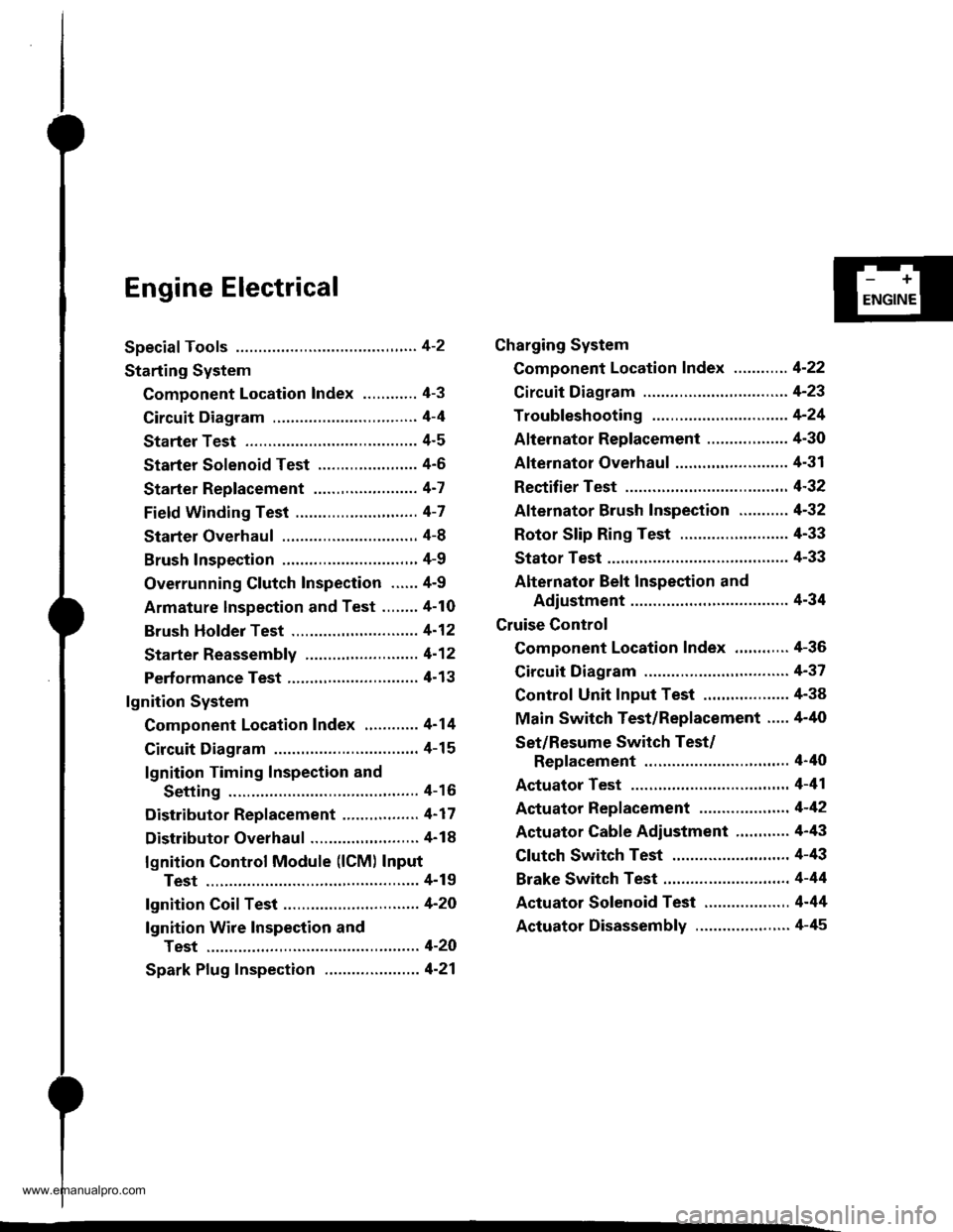
Engine Electrical
Speciaf Tools ............. 4-2
Starting System
Component Location Index ............ 4-3
Circuit Diagram ................................ 4-4
Starter Test ........... 4-5
Starter Solenoid Test ...................... 4'5
Starter Replacement ....................... 4-7
Field Winding Test ........................... 4-7
Starter Overhaul ............................,. 4-8
Brush Inspection ...........................,., 4-9
Overrunning Glutch Inspection ...... 4-9
Armature lnspection and Test ........4-10
Brush Holder Test ............................ 4-12
Starter Reassemb|y ......................... 4-1 2
Perf ormance Test ............................. 4- 1 3
lgnition System
Component Location Index ............ 4-14
Circuit Diagram ................................ 4-15
lgnition Timing Inspection and
Setting .......................................... 4-16
Distributor Replacement ........,........ 4-17
Distributor Overhaul .............,,......... 4-18
lgnition Control Module (lCM) Input
Test ..............................,................ 4-19
fgnition Coil Test .............................. 4-2O
lgnition Wire Inspection and
Test ............................................... 4-20
Spark Plug Inspection ..................... 4-21
-+
ENGINE
Charging System
Component Location Index ............ 4-22
Circuit Diagram ....................,........... 4-23
Troubleshooting .............................. 4-24
Alternator Replacement ..........,....... 4-30
Alternator Overhaul .......,,................ 4-31
Rectifier Test .........4-32
Alternator Brush Inspection ........... 4-32
Rotor Slip Ring Test ........................ 4-33
Stator Test ............. 4-33
Alternator Belt Inspection and
Adiustment ........4-34
Gruise Control
Component Location Index .,,,........ 4-36
Circuit Diagram ................................ 4-37
Control Unit Input Test ................... 4-38
Main Switch Test/Replacement ..... 4-40
Set/Resume Switch Test/
Replacement .......................,........ 4'40
Actuator Test ....,,., 4-41
Actuator Replacement ...............,.... 4-42
Actuator Cable Adiustment ............ 4-43
Clutch Switch Test .......................... 4-43
Brake Switch Test .................. .......... 4-44
Actuator Solenoid Test .............. ...,. 4-44
Actuator Disassembly ..................... 4-45
www.emanualpro.com
Page 72 of 1395

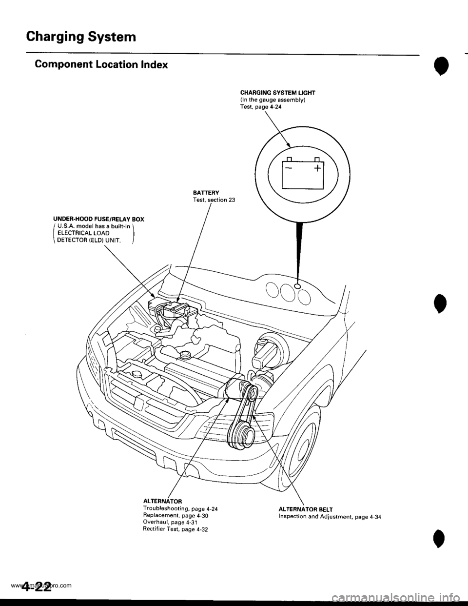
Charging System
Component Location Index
ALTERNATOR
CHARGING SYSTEM LIGHT(ln the gauge assembly)Test, page 4-24
BATTERYTest,
Troubleshooting, page 4-24Replacement, page 4-30Overhaul, page 4-31Rectifjer Test, page 4,32
ALTERNATOR BELTInspection and Adjustment, page 4 34
4-22
www.emanualpro.com
Page 80 of 1395

Charging System
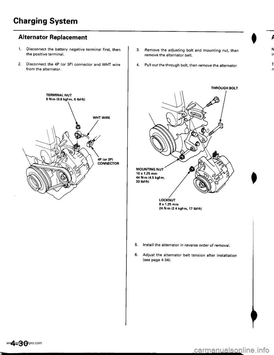
Alternator Replacement
't.Disconnect the battery negative terminal first, thenthe positive terminal.
Disconnect the 4P (or 3P) connector and WHT wirefrom the alternator.
WHT WIRE
4-30
'll
Remove the adjusting bolt and mounting nut, thenremove the alternator belt.
Pull out the through bolt, then remove the alternator.
THROUGH BOLT
ll^I}v
N
ir
T
n
MOUNTING NUT10 x 1.25 mm44 N.m 14.5 kgf.m.33 tbtfttt
o.
LOCKNUT8 x 1 .25 mm24 N.m (2.4 kgt m, 17 lbl.ft,
Install the alternator in reverse order of removal.
Adjust the alternator belt tension after installation(see page 4-34).
www.emanualpro.com
Page 126 of 1395

CKF Sensor
Replacement
1.
|o|'ln PUUCY BMCKET SOLIl0 r 1.25 mm14 .m 14.5 kgl.m,3:' lbtftl
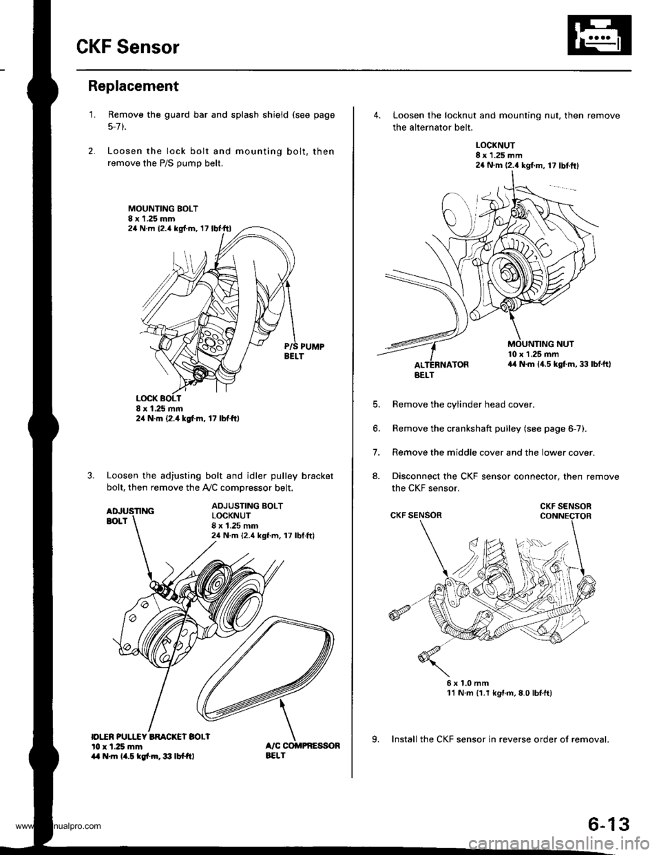
Remove the guard bar and splash shield (see page
5-7 t.
Loosen the lock bolt and mounting bolt, then
remove the P/S pump belt.
MOUNTING BOLT8 x 1.25 mm
PUMPBELT
Loosen the adjusting bolt and idler pulley bracket
bolt, then remove the Ay'C comDressor belt.
ADJUSTING BOLTLOCKNUT8 x 1.25 mm24 N.m {2.4 kgf.m, 17 lbf.ft)
24 N.m (2.{ kgf.m, 17 lbf.ttl
24 N.m 12.4 lgf.m, 17 lbl.ftl
4. Loosen the locknut and mounting nut, then remove
the alternator belt.
LOCKNUT8 x 1.25 mm24 N.m (2.4 kgl.m, 17 lbtftl
10 x 1 .25 mma4 N.m (4.5 kgt m, 33 lbtft)
E
6.
7.
aJ.
Remove the cylinder head cover.
Remove the crankshaft pulley (see page 6-7).
Remove the middle cover and the lower cover.
Disconnect the CKF sensor connector, then remove
the CKF sensor.
6x1.0mm11 N.m {1.r kgnm,8.0 lbfft)
9. Install the CKF sensor in reverse order of removal.
BELT
CKF SENSOR
6-13
www.emanualpro.com