clutch master cylinder HONDA CR-V 1998 RD1-RD3 / 1.G Workshop Manual
[x] Cancel search | Manufacturer: HONDA, Model Year: 1998, Model line: CR-V, Model: HONDA CR-V 1998 RD1-RD3 / 1.GPages: 1395, PDF Size: 35.62 MB
Page 41 of 1395

Lubrication Points
For the details of lubrication points and type of lubricants to be applied. refer to the illustrated index and various work pro-
cedures (such as Assembly/Reassembly, Replacement, Overhaul, Installation, etc.) contained in each section.
Recomm6nded Engine OilEngine oil viscosity for ambient temperature ranges
100'F
-30 -20 .10 0 10 20 30 40'c
r1: Always use Genuine Honda Manual Transmission Fluid {MTF). Using motor oil can cause stiffer shifting because it
does not contain the orooer additives.*2: Always use Genuine Honda Premium Formula Automatic Transmission Fluid (ATF). Using a non-Honda ATF can affect
shift qualitv.+3r Always use Genuine Honda DOT 3 Brake Fluid. Using a non-Honda brake fluid can cause corrosion and decrease the
life of the system.*4: Always use Genuine Honda Power Steering Fluid. Using any other type of power steering fluid or automatic transmis-
sion fluid can caused increased wear and poor steering in cold weather.
API SERVICE LABEL
/,.*-G\
/.'z-\e\t/6AE\ll-;-1 5w-30 /---l
w
API CERTIFICATION SEAL
ffi-20 0 20
NO.LUBRICATION POINTSLUBRICANT
EngineAPI Service Grade: Use SJ "Energy Conserving" grade oil. The oilcontainer may also display the API Certitication seal shownbelow. Make sure it says "For Gasoline Engines." SAE vjscosity:See chart below.
2
TransmissionManualGenuine Honda MTF*1
AutomaticGenuine Honda Premium Formula Automatic Transmission Fluid(ATF)*'
3Rear differentialGenuine Honda CVT Fluid
4Brake line (includes ABS line)Genuine Honda DOT 3 Brake Fluid*3
5Clutch LineBrake fluid DOT 3 or DOT 4*3
6Shift lever pivots (Manual transmission)Grease with molybdenum disultide
1Release fork (Manual transmission)LJrea Grease UM264 P/N 4'1211 - PYs - 305
IPower steering gearboxSteering grease P/N 08733 - B070E
Throttle cable end {Dashboard lower panel holelSilicone grease
10l112
14
Throttle cable end (Throttle link)Brake master cylinder pushrodPedal linkageBattery terminalsFuelfill lidClutch master cylinder pushrod
Multi purpose grease
1617181920
Hood hinges and hood lockTailgate hingesHatch glass hingesDoor hinges, upper and lowerDoor opening detent
Honda White Lithium Grease
21
22
Caliper Piston seal, Dust seal,Caliper pin, PistonShilt cable and select cable {Manual transmission)Silicone grease
23Brake line ioints (Front and rear wheelhouse)Rust preventives
24Power steering systemGenuine Honda Power Steering Fluid-.
25Air conditioning compressorCompressor oil: SP 10 lP/N 38897 - P13 - A0lAH or38899-P13-A01)For Refrigerant: HFC 134a (R,134a)
3-2
www.emanualpro.com
Page 428 of 1395
Clutch
Speciaf Tools ....,..... ..........' 12-2
lllustrated lndex ........... .'." 12'3
Clutch Pedal
Adjustment ........."."."".12-4
Clutch Master Cylinder
RemovaUlnstallation '." 12'5
Slave Cylinder
Removal/lnstallation .'.. 12-6
Pressure Plate
RemovaUlnspection ..'." 12-7
Clutch Disc
Removal/lnspection ."'.. 12-8
Flywheel
Inspection ...................... 12-9
Replacement ....................................... 1 2-9
Clutch Disc, Pressure Plate
lnstallation ....................' 12-10
Release Bearing
Removal/lnspection ...... 12'11
lnstaflation ..................... 12-12
www.emanualpro.com
Page 430 of 1395
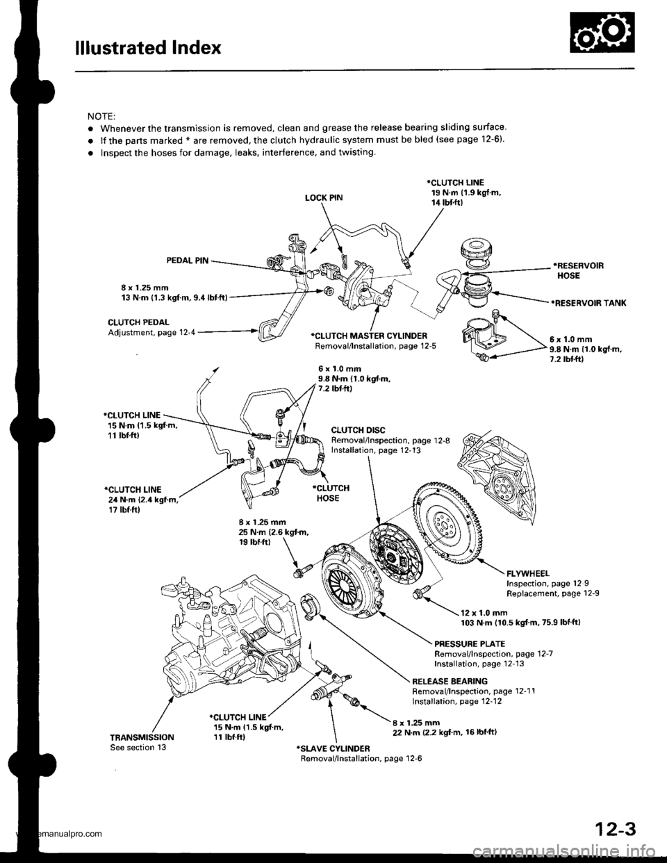
lllustrated Index
NOTE:
. Whenever the transmission is removed, clean and grease the release bearing sliding surface
.lfthepansmarked*areremoved,theclutchhydraulicsystemmustbebled(seepage1\
2-6).
. Inspect the hoses for damage. leaks. interference, and twisting.
LOCK PIN
*CLUTCH LINE19 N.m (1.9 kgj.m,14 tbtft)
8 x 1.25 mm13 N.m {1.3 kgf m,9.4lbtft)
PEDAL PIN.RESEFVOIR
HOSE
*RESERVOIR TANK
CLUTCH PEDALAdjustment, page 12-4*CI-UTCH MASTER CYLINDERFemoval/lnstallation, page 12-5
6x1.0mm9.8 N.m (1.0 kgf.m,7.2 tbf.ft)
*CLUTCH LINE15 N.m (1.5 kgt m,11 tbr.ft)
*CLUTCH LINE24 N.m {2.4 kgf.m,17 tbf.ft)
CLUTCH DISCRemoval/lnspection, page 1 2-8Installation, page 12,13
8 x 1.25 mm25 N.m {2.6 kgt m,19 rbf.ftt
I x 1.25 mm22 N.m 12.2 kgl'm, 16lbfft)
.o-.9r
WM\,".0--
ffi-P"8Nmlloks{m'
FLYWHEELInspection, page 12IRepiacement, page 12-9
12 x 1.0 mm103 N.m (10.5 kgtm,75.9 lbf ftl
PRESSURE PLATERemoval/lnspection, page'12-7
Installation, page'12 13
RELEASE BEARINGRemoval/lnspection, page 12-1'!Installation, page 12-12
*CLUTCH LINE15 N.m (1.5 kgt m,11 tbf.ft)
12-3
www.emanualpro.com
Page 431 of 1395
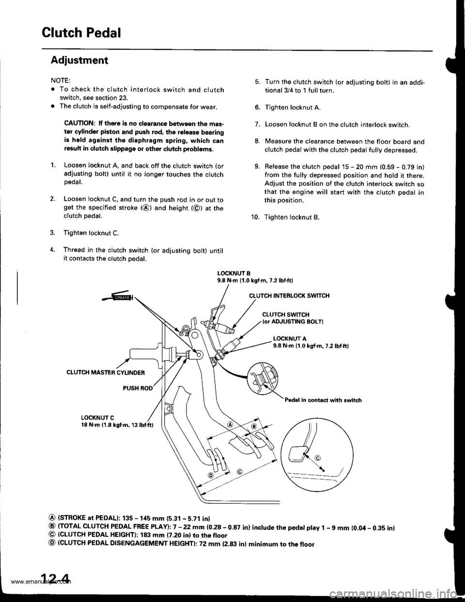
Clutch Pedal
Adiustment
NOTE:
. To check the clutch interlock switch and clutch
switch, see section 23.
. The clutch is self-adjusting to compensate for wear.
CAUTION: lf there is no clearance bstwa€n the mas-
ter cylinder piston and push rod, ths roloase bearingis held againsi the diaphragm spring, which canresuh in clutch slippage or other clutch probloms.
1. Loosen locknut A, and back off the clutch switch (or
sdjusting bolt) until it no longer touches the clutchpeoar.
2. Loosen locknut C, and turn the push rod in or out toget the specified stroke (@) and height (@) at theclutch oedal.
3. Tighten locknut C.
4. Thread in the clutch swirch (or adjusting bolt) untilit contacts the clutch oedal.
7.
5.
8.
q
Turn the clutch switch {or adjusting bolt} in an addi-
tional 3/4 to 1 full turn.
Tighten locknut A.
Loosen locknut B on the clutch interlock switch.
Measure the clearance between the floor board and
clutch pedalwith the clutch pedal fully depressed.
Release the clutch pedal 15 - 20 mm (0.59 - 0.79 in)
from the fully depressed position and hold it there,Adjust the position of the clutch interlock switch sothat the engine will start with the clutch pedal in
this position.
Tighten locknut B.10.
LOCKNUT B9.8 N.m 11.0 kgf.m, 7.2 lbf.ftl
CLUTCH INTERLOCK SWITCH
CLUTCH SWTTCH{or ADJUSTING BOLTI
L(rcKNUT A9.8 N.m {1.0 kg{.m,7.2 lbf.ftl
CLUTCH MASTER CYLINDER
PUSH ROD
Pedal in contact with swhch
LOCKNUT C18 N.m (1.8 kgf.m, 13lbtftl
@ {STROKE at PEDAL): 135 - 1its mm (5.31 - 5.71 in}
@ (TOTAL CLUTCH PEDAL FREE PLAY)i7 -22mm (0.28-0.87 in) inctude the pedat ptay 1 - 9 mm (0.0it- 0.35 inl@ (GLUTC,H PEDAL HE|GHTI: ltxt mm (7.20 inl ro rhe ftoor
o (CLUTCH PEDAL DTSENGAGEMENT HEtcHTl: 72 mm {2.txt inl minimum to the floor
\,/a_-_--/
12-4
www.emanualpro.com
Page 432 of 1395
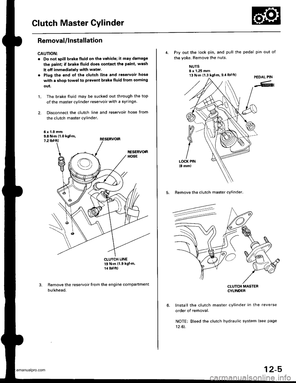
Glutch Master Cylinder
Removal/lnstallation
CAUTION:
. Do not spill brake fluid on the vehicle; it may damage
the paint; if brake tluid does contact the paint. wash
it off immediately with water.
. Plug the end ol the clutch line and leservoir hose
with a shop towel to prevent brake tluid trom coming
out.
The brake fluid may be sucked out through the top
of the master cylinder reservoir with a syringe.
Disconnect the clutch line and reservoir hose from
the clutch master cylinder,
't.
9.8 N.m 11.0 kst m,7.2 tbf.ftl
CLUTCH LINE
19 N'm 11 9 kgJ m'
14 lbf.frl
Remove the reservoir from the engine compartment
bulkhead.
13 N.m t1.3 kgt.m,g.il lbtft)
4. Prv out the lock pin, and pull the pedal pin out of
the voke. Remove the nuts.
NUTSI x 1.25 mm
5, Remove the clutch master cylinder.
CLUTCH MASTERCYLINDEF
Install the clutch master cylinder in the reverse
order of removal.
NOTE: Bleed the clutch hydraulic system {see page
12-61.
12-5
www.emanualpro.com
Page 433 of 1395
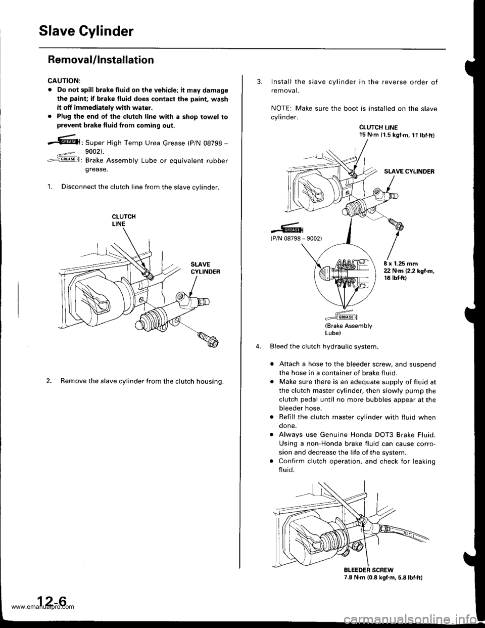
Slave Cylinder
RemovaUlnstallation
CAUTION:
. Do nol spill brake tluid on the vehicle; itmaydamage
the paint; if brake fluid do€s contast the paint, wash
it off immediately with water.. Plug the end of the clutch line with a shop towel toprevcnt brake tluid from coming out.
.6|l,Super High Temp Urea crease (p/N 08798 -
9002).
: Brake Assembly Lube or equivalent rubber
grease.
1. Disconnect the clutch line from the slave cvlinder.
2. Remove the slave cylinder from the clutch housing.
12-6
3. Install the slave cylinder in the reverse order ot
removal.
NOTEr Make sure the boot is installed on the slave
cylinder.
CLUTCH LINE15 N.m (i.S kgf.m, lt tbf.ftl
SLAVE CYLINDER
.-lG(P/N 08798 - 90021
E x 1.25 mm22 N.m (2.2 kgt.m,16 tbtft)
(Brake AssemblyLube)
Bleed the clutch hydraulic system.
Attach a hose to the bleeder screw, and suspend
the hose in a container of brake fluid.
Make sure there is an adequate supply of fluid at
the clutch master cylinder, then slowly pump the
clutch pedal until no more bubbles appear at the
bleeder hose.
Refill the clutch master cylinder with fluid whenqone.
Always use Genuine Honda DOT3 Brake Fluid.
Using a non Honda brake fluid can cause corro-
sion and decrease the life of the system.
Confirm clutch operation, and check for leaking
fluid.
7.8 N.m (0.8 kgf.m. 5.8 lbt.ft)BLEEDER SCREW
www.emanualpro.com