crankshaft fluctuation sensor HONDA CR-V 1998 RD1-RD3 / 1.G Workshop Manual
[x] Cancel search | Manufacturer: HONDA, Model Year: 1998, Model line: CR-V, Model: HONDA CR-V 1998 RD1-RD3 / 1.GPages: 1395, PDF Size: 35.62 MB
Page 114 of 1395
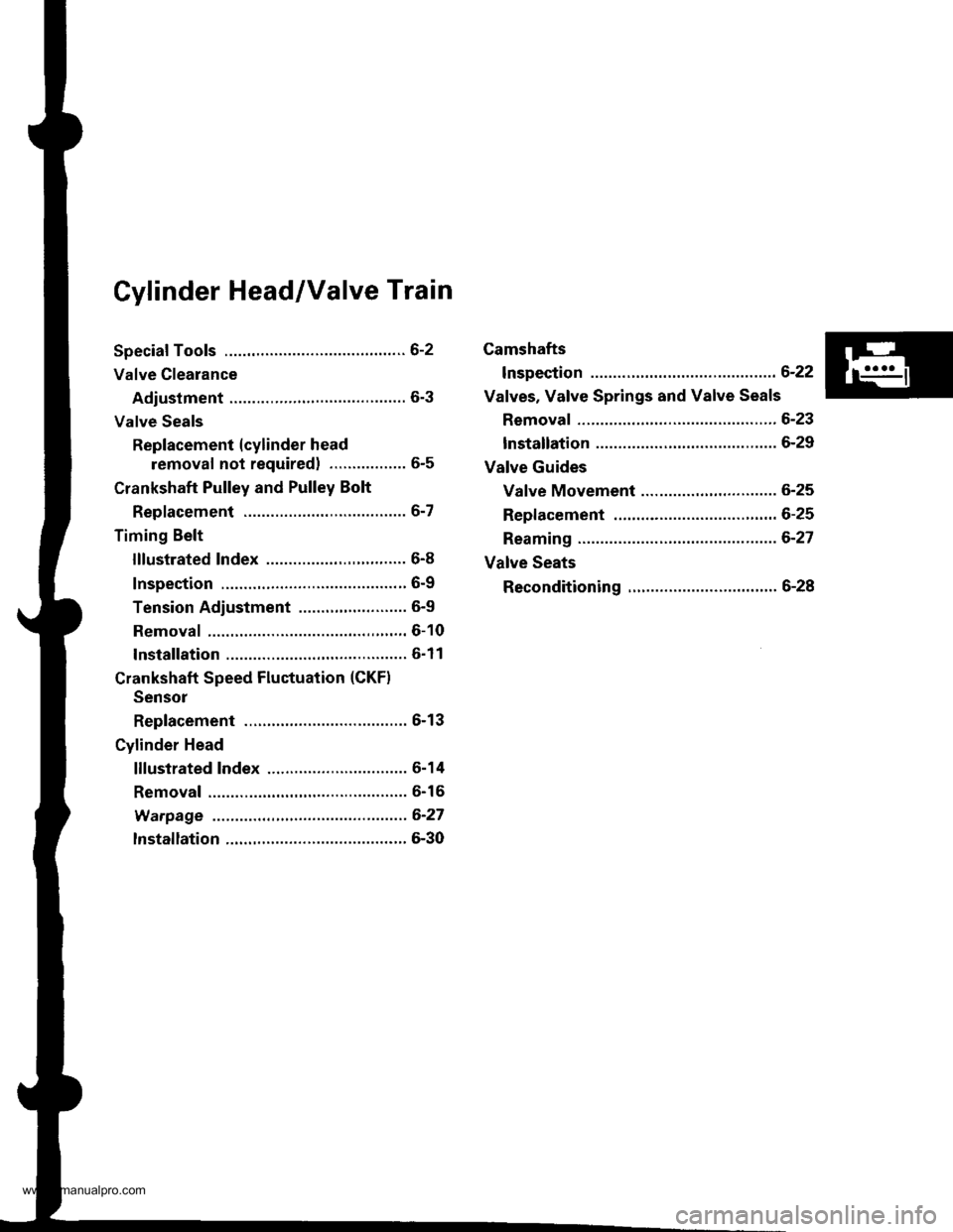
Cylinder Head/Valve Train
Speciaf Tools .............6-2
Valve Clearance
Adiustment ............6-3
Valve Seals
Replacement (cylinder head
removal not requiredl ................. 6-5
Crankshaft Pulley and Pulley Bolt
Replacement .........6-7
Timing Belt
I llustrated lndex ............................... 6-8
Inspection ............., 6-9
Tension Adjustment ........................ 6-9
Removal ...........,..... 6-10
lnstallation .............6-11
Crankshaft Speed Fluctuation (CKFI
Sensor
Replacement .........6-13
Cylinder Head
lllustrated lndex ............................... 6-14
Removal .................6-16
Warpage ................6-27
lnstallation ............. 6-30
Camshafts
lnspection ..............6-22
Valves, Valve Springs and Valve Seals
Removal ................, 6-23
lnstallation ............. 6-29
Valve Guides
Valve Movement ............,,,,.,............ 6-25
Replacement .........6-25
Reaming .................6-27
Valve Seats
Reconditioning ......6-28
www.emanualpro.com
Page 121 of 1395
Timing Belt
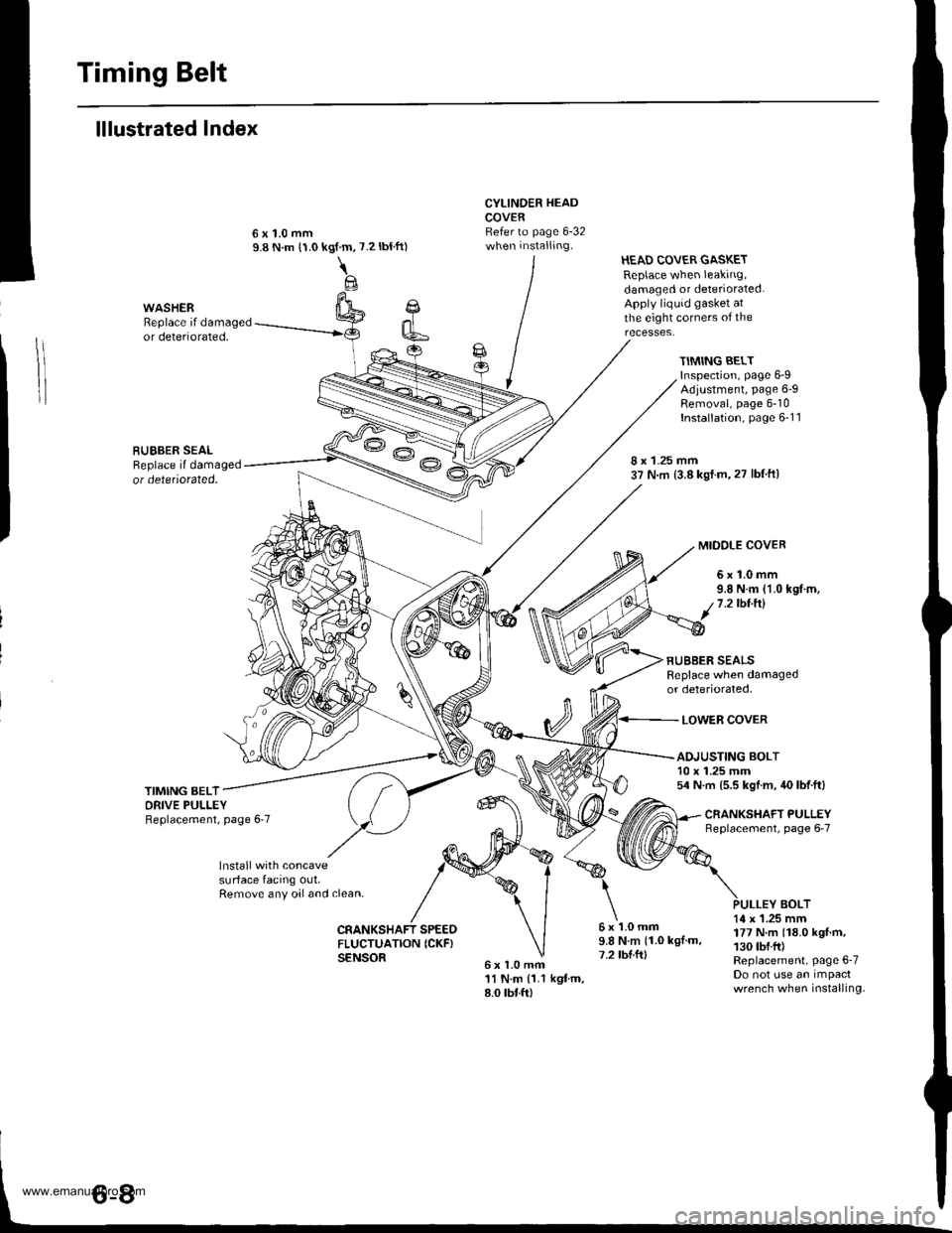
lllustrated Index
Cl
k6
CYLINDER HEADCOVERRefer to page 6-32when installing.
6x1.0mfi11 N.m {1.1 kgtm,8.0 rbtft)
HEAD COVER GASKETReplace when leaking,damaged or deteriorated.Apply liquid gasket atthe eight corners of theWASHERReplace if damagedor deteriorated,
RUEBER SEALReplace il damagedot detetiorated.
kgf.m,
\@
7.2 tbtft)
TIMING BELTInspection, page 6-9Adjustment, page 6-9Removal, page 6-10Installation, page 6-1 1
8 x 1.25 mm37 N.m (3.8 kst.m,27 lbf ftl
MIDOLE COVER
6x1.0mm9.8 N.m {1.0 kgf.m,1.2lbt.ftl
RUBBER SEALSReplace when damagedor deteriorated,
LOWER COVER
TIMING BELTORIVE PULLEYReplacement, page 6'7
ADJUSTING BOLT10 x 1.25 mm54 N.m (5.5 kgl.m, 40 lbf.ft)
CNANKSHAFT PULLEYneplacement, page 6-7
lnstall with concavesurface facing out,Remove any oal and clean,BOLT
CRANKSHAFT SPEEOFLUCTUATION ICKF}SENSOR
6x1.0mm9.8Nm(1.0kgl.m,7.2 tbl.ft)
14 x 1.25 mm177 N.m (18.0 kgf'm,130 tbf.fr)Replacement, Page 6-7Do not use an impactwrench when installing.
www.emanualpro.com
Page 206 of 1395
Component Locations
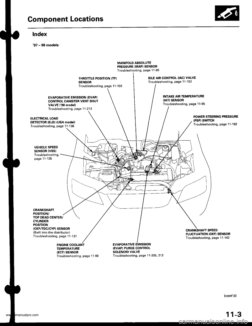
lndex
'97 - 98 models:
MANIFOLD ABSOLUTEPRESSURE IMAP} SENSORTroubleshooting, Page 1 1-90
THROTTLE POSITION (TP}
SENSORTroubleshooting, page 1 1-103
toLE AtR CONTROL llAcl VAI-VE
Troubleshooting, page 1 1-152
EVAPORATIVE EMISSION (EVAP)
CONTROL CANISTER VENT SHUTVALVE t'98 mod€llTroubleshooting, page 11'213
INTAKE AIR TEMPERATUREIIATI SENSORTroubleshooting. page 1 'l -95
ELECTRICAL LOADDETECTOR IELD) (USA modol)Troubleshooting, page 1 1-138
VEHICLE SPEEDSENSOR (VSS)
Troubleshooting,page 11'135
CRANKSHAFTPOSTTtON/
POWER STEERING PRESSURElPsPl swtrcHTroubloshooting, page 1 1-162
TOP OEAD CENTER/CYLINDERPOStTtON{CKP/TDC/CYP} SENSOR(Built into the distributor)Troubleshooting, page 1 l-131
CMNKSHAFT SPEEDFLUCTUATION ICKF} SENSORTroubleshooting. page 1'!-142
ENGINE COOLANTTEMPERATUREIECTI SENSORTroubleshooting, page 11 99
EVAPORATIVEI€VAP) PURGE CONTROLSOLENOID VALVETroubf eshooting, page 1 1'2o5, 213
(cont'd)
11-3
www.emanualpro.com
Page 207 of 1395
Component Locations
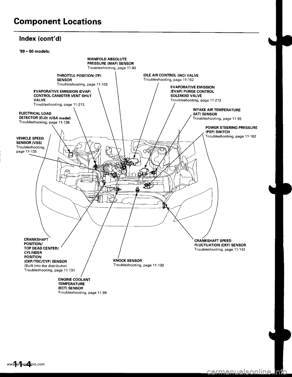
Index (cont'dl
39 - 00 models:
MANIFOLD ABSOLUTEPRESSURE IMAPISENSORTroubleshooting, page 1 1-90
THROTTLE POSITION {TP)SENSORTroubleshooting, page 1 1-103
IDLE AIR CONTROL OACI VALVETroubleshooting, page 1 1-152
EVAPOBATIVE EMISSION {EVAPICONTROL CANISTER VENT SHUTVALVETroubleshooting, page 1 1-213
EVAPORATIVE EMISSION(EVAPI PURGE CONTROI-SOLENOID VALVETroubleshootang, page 1 1-2'13
ELECTRICAL LOAOOETECTOR {ELD) IUSA modet)Troubleshooting, page I 1-138
INTAKE AIR TEMPERATURE(IAT) SENSORTroubleshooting, page 11 95
POWEB STEERING PRESSUREtPsPt swtTcHTroubleshooting, page 11 162VEHICLE SPEEDSENSOR IVSSITroubleshooting,page 11'135
CRANKSHAFTPOSTTTON/TOP OEAD CENTER/CYLINDERPOStTtON{CKP/TDC/CYP) SENSOR(Built into the distributor)Troubleshooting, page 11 131
CRANKSHAFT SPEEDFLUCTUATION ICKN SENSORTroubleshooting, page 1 1-142
SENSORTroubleshooting, page '11 130
ENGINE COOLANTTEMPERATURE{ECT)SENSORTroubleshooting, page 11 99
11-4
www.emanualpro.com
Page 213 of 1395
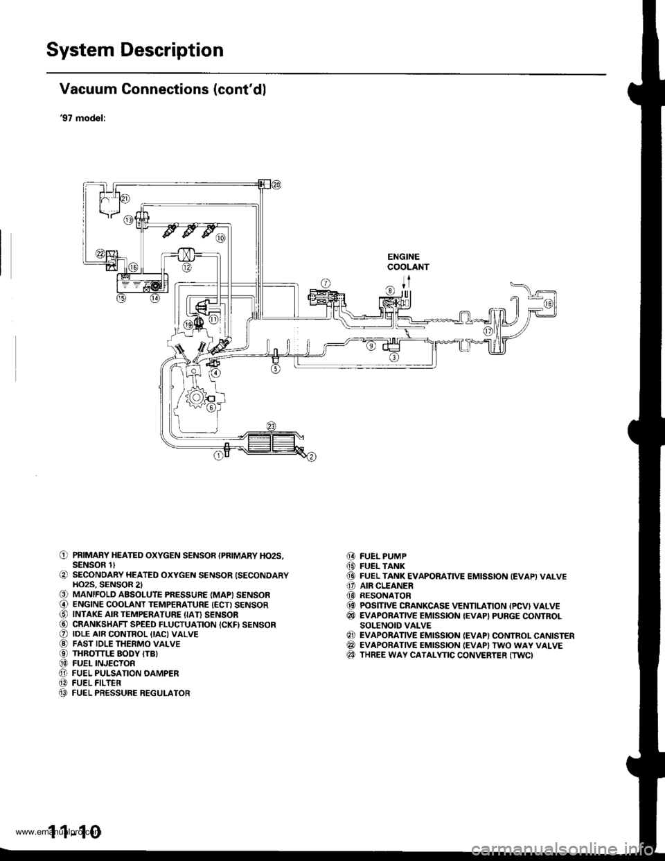
System Description
Vacuum Connections (cont'dl
'97 model:
ENGINECOOLANT
ITr|ll
O PRIMARY HEATED oxYGEN sENsoR {PRIMARY Ho2s,SENSOR lt
O SECONDARY HEATED oxYGEN sENsoR {SECoNDARYHO2S. SENSOR 2l€) MANIFOLD ABSOLUTE PRESSURE (MAPI SENSOR@ ENGINE cooLANT TEMPERATURE {EcT} sENsoRO INTAKE AIR TEMPERATURE (IAI} sENsoR@ CRANKSHAFT SPEED FLUCTUATION ICKFI SENSORO |DLE ArR coNTRoL {tAc)vALvE@ FAST IDLE THERMo vALvEO THRoTTLE EoDY ITB)@ FUEL INJEcTonO FUEL PULSATIoN oAMPER@ FUEL FILTEn(} FUEL PRESSURE REGULATOR
FUEL PUMPFUEL TANKFUEL TANK EVAPORATIVE EMISSION (EVAPIVALVEAIR CLEANERRESONATORPOSITIVE CRANKCASE VENTILATION {PCVI VALVEEVAPORATIVE EMISSION {EVAP} PURGE CONTROLSOI.'ENOID VALVEEVAPORATIVE EMISSION {EVAP) CONTROL CANISTEREVAPORATIVE EMISSION {EVAPI TWO WAY VALVETHREE WAY CATALYTIC CONVERTER (TWC)
@(D(D
o@(}
@
@@@
1 1-10
www.emanualpro.com
Page 215 of 1395
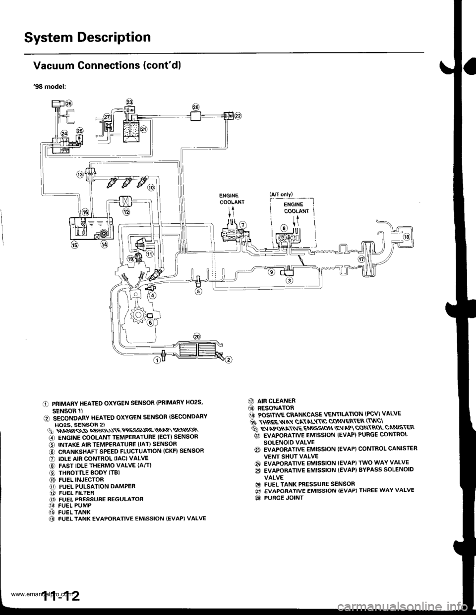
System Description
I
I
I
Vacuum Connections (cont'dl
'98 model:
C PRIMARY HEATEO OXYGEN SENSOR (PRIMARY HO2S,
SENSOR 1)(, SECONDARY HEATEO OXYGEN SENSOR ISECONDARYHO2S, SENSOR 2)(!)\\\\ss\SNBSS\\\ETRESS\RE\\NQ\SE\SSR
G) ENGINE COOLANT TEMPERATUBE (ECT) SENSOR
O INTAKE AIR TEMPERATURE {IAT} SENSOR
@ CRANKSHAFT SPEED FLUCTUATION (CKFI SENSOR
O IDLE AIR CONTROL (IAC) VALVE
@ FAST IDLE THERMO VALVE (A/T)
O THROTTLE BODY (TBI(0) FUEL INJECTOR.1' FUEL PULSATION DAMPER.14 FUEL FILTER(i FUEL PRESSURE REGULATOR14 FUEL PUMP(D FUEL TANK@ FUEL TANK EVAPORATIVE EMISSION {EVAPI VALVE
C] AIR CLEANER(O RESONATOR1iC POSITIVE CRANKCASE VENTILATION (PCV) VALVE
6 \$REE$IN gN NL$\C CON\ER\ER (TNC\
ti q rpos,xr E qN
ssros \E aP cqN\RoLcaNtsr€R
@ EVAPORATIVE EMISSION IEVAP) PURGE CONTROL
SOLENOID VALVEq3 EVAPORATIVE EMISSTON IEVAP} CONTROL CANISTER
VENT SHUT VALVE
@ EVAPORATIVE EMISSION (EVAP) TWO WAY VALVE
€i EVAPORATIVE EMISSION {EVAP) BYPASS SOLENOID
VALVE
€9 FUEL TANK PRESSURE SENSOROi EVAPORATIVE EMISSION {EVAP) THREE WAY VALVE
Qd PURGE JOINT
G/T only)
f
-i*'";-t
COOLANT Jt
U
11-12
www.emanualpro.com
Page 217 of 1395
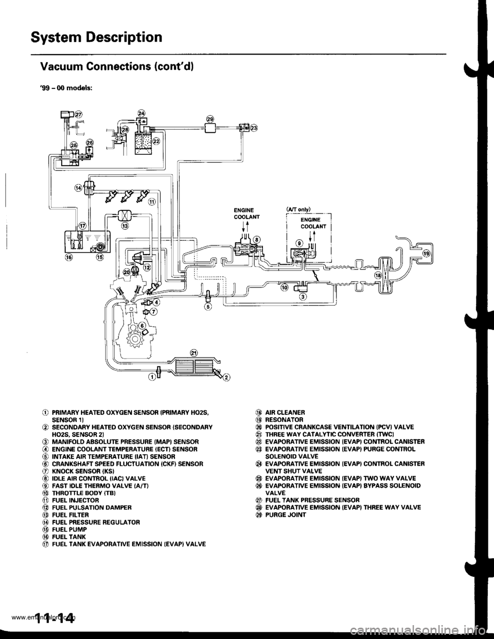
System Description
Vacuum Connections (cont'dl
'99 - q) models:
ENGINECOOLANT
t
o
o
o@
o@@@@@@@@@(t
PRIMARY HEATED OXYGEN SENSOR IPRIMARY HO2S,SENSOR 1lSECONDARY HEATED OXYGEN SENSOR {SECONDARYHO2S. SENSOR 2lMANIFOLD ABSOLUTE PRESSURE (MAPI SENSORENGINE COOLANT TEMPERATURE IECN SENSORINTAKE AIR TEMPERATURE IIATI SENSORCRANKSHAFT SPEED FLUCTUATION {CKF) SENSORKNOCK SENSOR (KS}
IDLE AIR CONTROL IIACI VALVEFAST IDLE THERMO VALVE {A/T}THROTTLE BODY (TB}
FUEL INJECTORFUEL PULSATION DAMPERFUEL FILTERFUEL PRESSURE REGULATORFUEL PUMPFUEL TANKFUEL TANK EVAPORATIVE EMISSION (EVAPI VALVE
AIR CLEANERRESONATORPOSITIVE CRANKCASE VENTILATION (PCV} VALVETHREE WAY CATALYTIC CONVERTER ITWCIEVAPORATIVE EMISSION {EVAPI CONTROL CANISTEREVAPORATIVE EMISSION IEVAPI PURGE CONTROLSOLENOID VALVEEVAPORATIVE EMISSION {EVAPI CONTROL CANISTEFVENT SHUT VALVEEVAPORATIVE EMISSION IEVAPI TWO WAY VALVEEVAPONANVE EMISSION {EVAPI AYPASS SOLENOIDVALVEFUEL TANK PRESSURE SENSOBEVAPORATIVE EMISSION IEVAPI THREE WAY VALVEPURGE JOINT
@@@@@@
@
@@
@@@
11-14
www.emanualpro.com
Page 280 of 1395
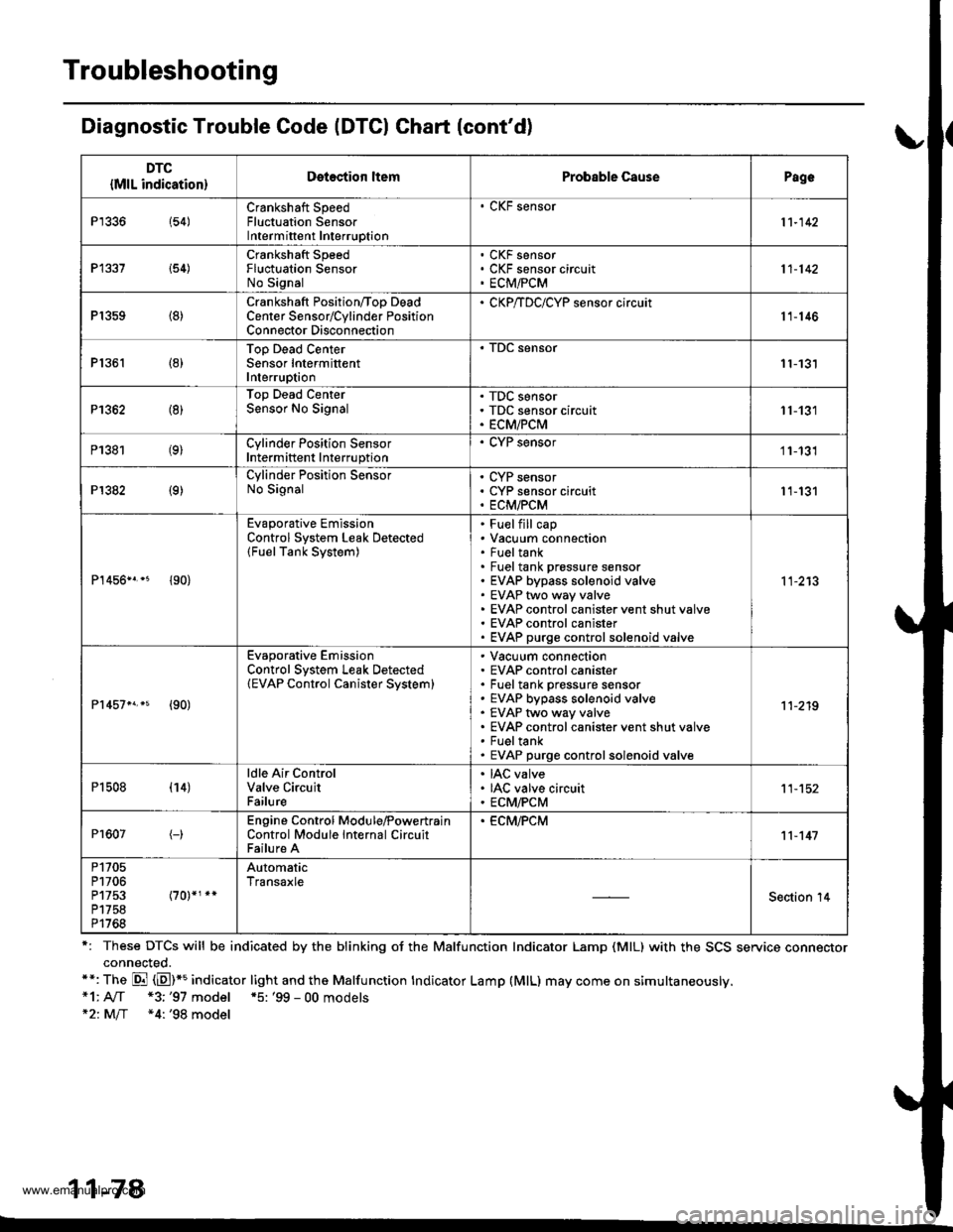
Troubleshooting
Diagnostic Trouble Code (DTCI Ghart (cont'd)
r: These DTCS will be indicated by the blinking oJ the Malfunction Indicator Lamp (MlL) with the SCS service connectorconnected.**: The Di (E)*5 indicator light and the Malfunction tndicator Lamp (MlL) may come on simultaneously.*1: A[f *3;'97 model *5: '99 - 00 models*21M/f *4: '98 model
11-78
DTC
{MlL indication}Detection ltemProbable CausePagc
P1336 154)Crankshaft SpeedFluctuation SensorIntermittent Interruption
. CKF sensor
11-142
P1337 i54)Crankshaft SpeedFluctuation SensorNo Signal
CKF sensorCKF sensor circuitECM,FCM11-142
P1359 (8)Crankshaft Position/Too DeadCenter Sensorrcylinder PositionConnector Disconnection
' CKP/TDC/CYP sensor circuit11-146
P1361 (8)Top Dead CenterSensor IntermittentInterruption11-131
P1362 (8)Top Dead CenterSensor No SignalTDC sensorTDC sensor circuitECM/PCM11-131
P1381 (9)Cylinder Position SensorIntermittent Interruption
. CYP sensor11-131
P1382 (9)Cylinder Position SensorNo SignalCYP sensorCYP sensor circuitECM/PCM11-131
P1456n.* {90}
Evaporative EmissionControl System Leak Detected(FuelTank System)
Fuelfill capVacuum connectionFueltankFuel tank prossure sensorEVAP bypass solenoid valveEVAP two way valveEVAP control canister vent shut valveEVAP control canisterEVAP purge controlsolenoid valve
11-213
Pr457n.s {90)
Evaporative EmissionControl System Leak Detected(EVAP Control Canister Svstem)
Vacuum connectionEVAP control canisterFuel tank pressure sensorEVAP bypass solenoid valveEVAP two way valveEVAP control canister vent shut valveFueltankEVAP purge controlsolenoid valve
11-219
P1508 (14)ldle Air ControlValve CircuitFailure
IAC valveIAC valve circuitECM/PCM11-152
Pr607(-)Engine Control Module,PowertrainControl Module Internal CircuitFailure A
. ECM,FCM11-147
P1705P1706P1753P1758P1768
AutomaticTransaxle
Section '14
www.emanualpro.com
Page 328 of 1395
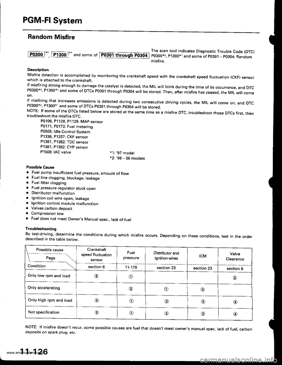
PGM-FI System
Random Misfire
lF()gool", tftod-' and some or lpiogol throughTo3oti
The scan tool indicates Diagnostic Trouble Code (DTC)
P0300*,, P1300*1 and some of po30t - pO3O4; Randommisfire.
Descriotion
Misfire detection is accomplished by monitoring the crankshaft speed with the crankshaft speed fluctuation (cKF) sensorwhich is attached to the crankshaft.lfmisfiring strong enough to damage the catalyst is detected, the MIL will blink during the time of its occurrence, and DTcP0300*'�, P1300*1 and some of DTCs P03ol through P0304 will be stored. Then, after misfire has ceased, the MtL will comeon,
lf misfiring that increases emissions is detected during two consecutive driving cycles, the MIL will come on, and DTcand some of DTCS p0301 through p0304 wi
be stored.NOTE: lf some of the DTCS listed below are stored at the same time as a misfire DTc, troubleshoot those DTcs first. thentroubleshoot the misfire DTC.
P0106, P]128, P1'129; MAp sensorP0171. P0172; Fuet metering
P0505: ldle Control Svstem
P1336, P1337; CKF sensor
P1361, P1362: TDC sensor
Pl381. Pl382: CYP sensor
P1508: IAC valve *1:,97 model*2: '98 - 00 models
Possiblo Caus€
. Fuel pump insufficient fuel pressure, amountofflow. Fuel line clogging. blockage, leakage. Fuel filter clogginga Fuel pressure regulator stuck open. Distributormalfunction
. lgnition coil wire open, leakage. lgnition control module malfunction. Valves carbon deposita Compression lowa Fuel does not meet Owner's Manual spec., lack offuel
Troubleshooting
By test-driving, determine the conditions during which misfire occurs. Depending on these conditions, test in the orderdescribed in the table below.
Possible cause
[ ;;;;- -....
Crankshaft
speed fluctuation
sensor
Fuel
pressureDistributor and
lgnition wirestcMValve
Clearance
Conditionsection 611-178section 23section 23section 6
Only low rpm and load,6)o
Only acceleratingooo
Only high rpm and loado@,a'@
Not specificationG\o@o@
NOTE: lf misfire doesn't recur, some possible causes are fuel that doesn't meet owner's manual spec, lack of fuel, carbondeposits on spark plu9, etc.
11-126
www.emanualpro.com
Page 329 of 1395
![HONDA CR-V 1998 RD1-RD3 / 1.G Workshop Manual
Misfire Detected in One Cylinder
Ipffi1] Thescantoot indicates Diagnostic Trouble Code (DTC) P0301: Cylinder 1 misfire detected.
lF03O2l 16".""n toot indicates Diagnostic Trouble Code (DTC) P0302; Cy HONDA CR-V 1998 RD1-RD3 / 1.G Workshop Manual
Misfire Detected in One Cylinder
Ipffi1] Thescantoot indicates Diagnostic Trouble Code (DTC) P0301: Cylinder 1 misfire detected.
lF03O2l 16".""n toot indicates Diagnostic Trouble Code (DTC) P0302; Cy](/img/13/5778/w960_5778-328.png)
Misfire Detected in One Cylinder
Ipffi1] Thescantoot indicates Diagnostic Trouble Code (DTC) P0301: Cylinder 1 misfire detected.
lF03O2l 16".""n toot indicates Diagnostic Trouble Code (DTC) P0302; Cylinder 2 misfire detected.
I P0303 | fne scan tool indicates Diagnostic Trouble Code (DTC) P0303: Cylinder3 misfire detected.
lF0il04l 16" ""un tool indicates Diagnostic Trouble Code (DTC) PO3O4: Cylinder 4 misfire detected
Description
Misfire detection is accomplished by monitoring the crankshaft speed with the crankshaft speed fluctuation (CKF) sensor
which is attached to the crankshaft.
lf misiiring strong enough to damage the catalyst is detected, the MIL will blink during the time of its occurrence. and DTC
P0301, P0302, P0303 and/or P0304 will be stored. Then, after the misfire has ceased, the MIL will come on.
lf misfiring that increases emissions is detected during two consecutive driving cycles. the MIL will come on, and DTc
P0301, P0302, P0303 and/or P0304 will be stored.
NOTE: lJ some of the DTcs listed below are stored at the same time as a misfire DTc, troubleshoot those DTcs first, then
troubleshoot the misfire DTC.
P0107, P0108, P'n2a, P1129t MAP sensor
Po'17 'l , P0112t Fuel suPP|Y system
P0441: EVAP insufficient Purge flow
P1336, P1337: CKF sensor
P1359, Pl361, P1362: TDC sensor
Pl381, P1382: CYP sensor
Possible Cause
. Fuel injector clogging, fuel leakage, air leakage
. Fuel injector circuit open or shorted
. Spark plug carbon deposits, fouling, malfunction
. lgnition wires open, leaking
. Distributor malfunction
. Compression low
. Valve clearance out of specification
(cont'd)
11-127
www.emanualpro.com