drain bolt HONDA CR-V 1998 RD1-RD3 / 1.G Workshop Manual
[x] Cancel search | Manufacturer: HONDA, Model Year: 1998, Model line: CR-V, Model: HONDA CR-V 1998 RD1-RD3 / 1.GPages: 1395, PDF Size: 35.62 MB
Page 100 of 1395
Engine Removal/lnstallation
Removal (cont'dl
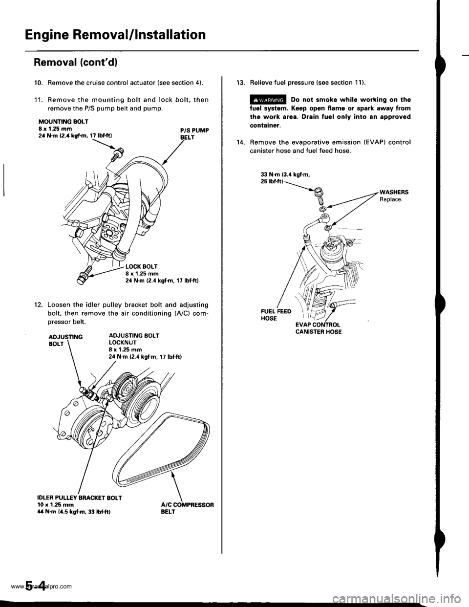
Remove the cruise control actuator (see section 4).
Remove the mounting bolt and lock bolt, then
remove the P/S pump belt and pump.
10.
1t.
MOUNNNG BOLT8 x 1.25 mm2a N.m 12.4 kg{.m, 17 lbtftlP/S PUMPBELT
LOCK BOLTI x 1.25 mm24 N.m {2.4 kgtm, '17 lbf.ftl
12.Loosen the idler pulley bracket bolt and adjusting
bolt, then remove the air conditioning (A,/C) com-
pressor belt.
ID1TR PULI.f,Y ARACKET BOLT10 r 1.25 mma{ N.m 14.5lgtm,33 lbf.ft)
ADJUSTING BOLTLOCKNUT8 x 1.25 mm24 N.m {2.4 kgf.m, 17 lbf.ftl
5-4
13. Relieve fuel pressure {see section 11).
@ Do not 3mok6 whil€ working on th6
tugl systsm. Koep open flam€ or spark away from
the work area. Drain fuel only inlo an approved
container.
14. Remove the evaporative emission (EVAP) control
canister hose and tuel feed hose.
33 N.m (3.4 kgt.m,2s tbf.ft)
,%l
*ryft'fltr
\'t,f
EVAP CCCANISTER HOSE
www.emanualpro.com
Page 103 of 1395
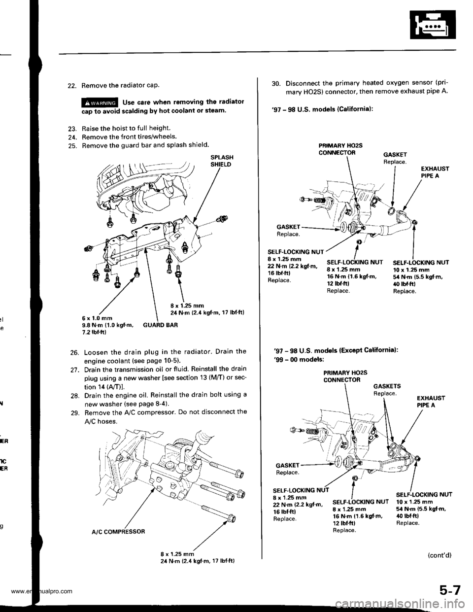
22. Remove the radiator caP.
!@ use care when removing the radiatol
cap to avoid scalding by hot coolani or steam.
23. Raise the hoist to full height
24. Remove the front tires/wheels.
25. Remove the guard bar and splash shield.
8 x 1.25 mm2,1 N.m {2.4 kgf,m, 17 lbl ft)6x1.0mm9.8 N.m {1.0 kgf.m, GUARD BAR7.2 tbf.rr)
Loosen the drain plug in the radiator. Drain the
engine coolant (see page 10-51.
Drain the transmission oil or fluid. Reinstall the drain
plug using a new washer lsee section 13 (M/T) or sec-
tion 14 (ly'T)].
Drain the engine oil. Reinstall the drain bolt using a
new washer {see page 8-4).
Bemove the A,/C compressor. Do not disconnect the
!y'C hoses.
SPLASH
26.
27.
28.
29.
ER
lCEB
30. Disconnect the primary heated oxygen sensor (prl-
mary HO2S) connector. then remove exhaust pipe A
'97 - 98 U.S. models (Cslifornia):
PRIMARY HO2SCONNECTOR
GASKETReplace.
SELF-LOCKING NUT8 x 1.25 mm22 N.m 12.2 kgf.m,16 lbf.ftlReplace.
8 x 1.25 mm16 N.m {1.6 kgf.m.12 tbt.ftlReplace.
SELF.LOCKING NUT10 x 1.25 mm54 N.m 15.5 kgf.m,.() tbf.frlReplace.
NUT
'97 - 98 U.S. mod€ls {Except California):'99 - 00 models:
PRIMARY HO2SCONNECTORGASKETSReplace.
GASKETReplace.
SELF.LOCKING8 x 'l.25 mm22 N.m (2.2 kgf m,
16 rbf.ftlReplace.
SELF.LOCKING NUT
8 x 1.25 mm16 N.m 11.6 kgf.m,12 tbt fr)Replace.
10 x 1.25 mm54 N.m 15.5 kgt.m,40 rbt.ftlReplace.
{cont'd)
5-7
www.emanualpro.com
Page 129 of 1395
Gylinder Head
Removal
Engine removal is not required for this procedure.
l!@ Make sure iacks and safety stands are
placed properly, and hoist blackels ale attachgd to the
correct position on the engine.
NOTE:
o Use fender covers to avoid damaging painted sur-
faces.
o To avoid damage, unplug the wiring connectors care-
fully while holding the connector portion.
. To avoid damaging the cylinder head, wait until the
engine coolant temperature drops below 100"F (38'C)
before loosening the retaining bolts.
. Mark all wiring and hoses to avoid misconnection.
Also, be sure that they do not contact other wiring or
hoses, or interfere with other parts.
2.
4.
5.
1.Disconnect the negative terminal from the battery.
Drain the engine coolant (see page 10-5). Remove
the radiator cap to speed draining.
Remove the intake air duct and air cleaner housing(see page 5-2).
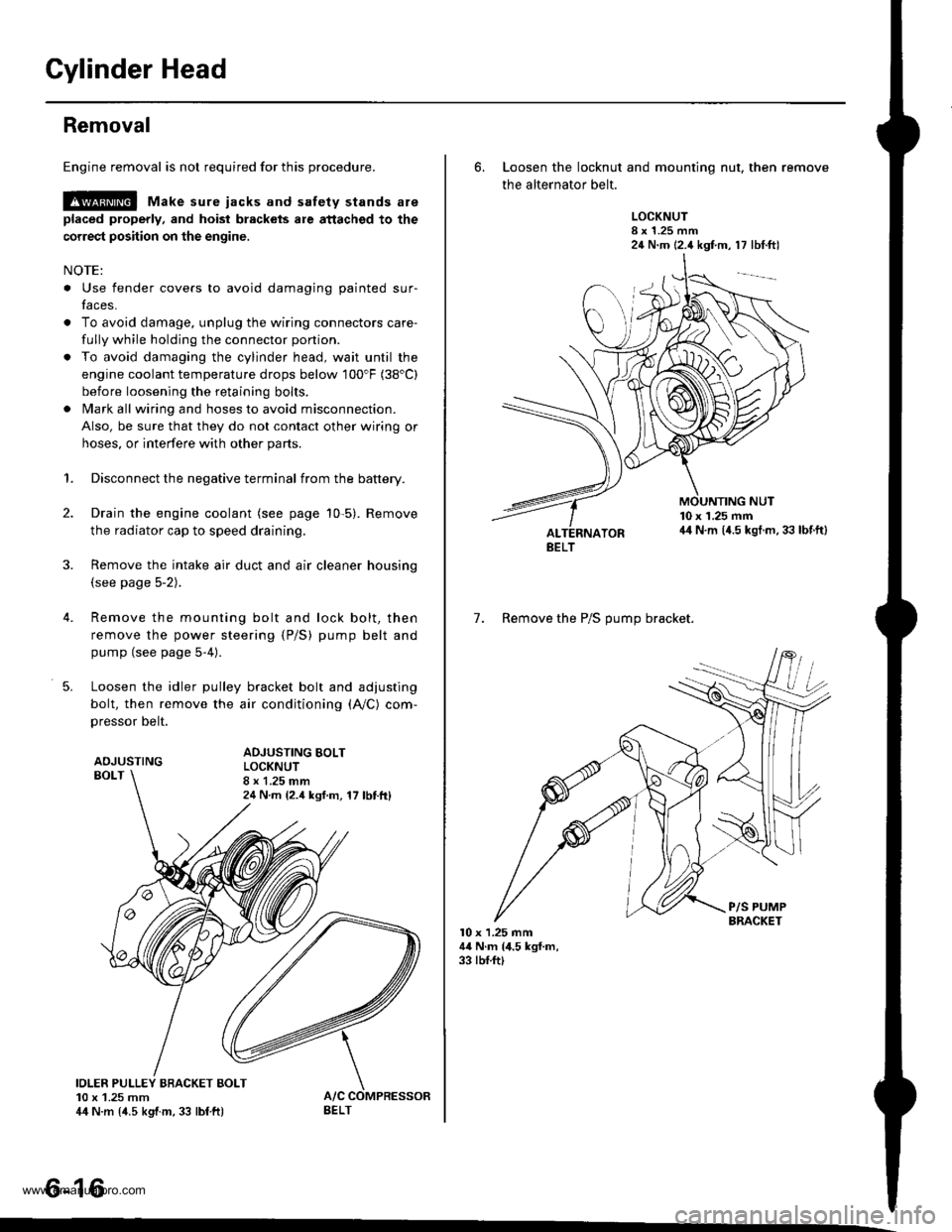
Remove the mounting bolt and lock bolt, then
remove the power steering (P/S) pump belt and
pump (see page 5-4).
Loosen the idler pulley bracket bolt and adjusting
bolt, then remove the air conditioning (A,/C) com,
pressor belt.
ADJUSTINGBOLT
ADJUSTING BOLTLOCKNUT8 x 1.25 mm24 N m {2.4 ksf.m, 17 lbttt}
IOLER PULLEY BBACKET BOLT10 x 1.25 mm44 N.m {4.5 kgtm, 33 lbf ft)
tt aAo-Io
6. Loosen the locknut and mounting nut, then remove
the alternator belt.
LOCKNUT8 x 1.25 mm24 N.m (2.4 kgf.m, 17 lbt.ftl
10 x 1.25 mm44 N.m (4.5 kgt.m. 33 lbf.ft)
7. Remove the P/S OUmo bracket.
l0 x 1.25 mm44 N.m (4.5 kgf.m,33 rbf.ft)
BELT
www.emanualpro.com
Page 173 of 1395
lllustrated Index
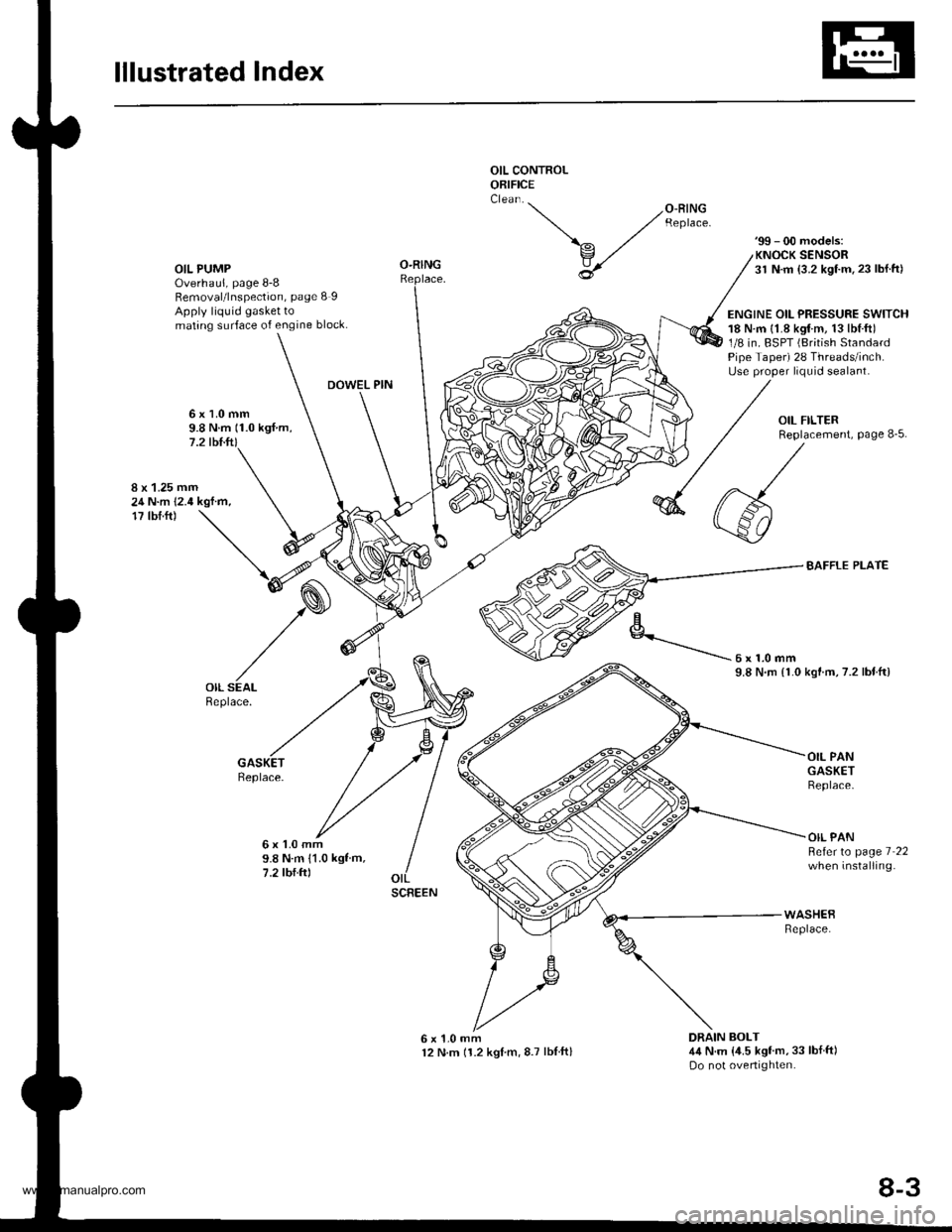
OIL CONTROLORIFICE
OIL PUMPOverhaul, page 8-8Removal/lnspection, page 8 IApply liquid gasket tomating surface of engine block.
'99 - 00 models:KNOCK SENSOR31 N.m {3.2 kgf.m.23 lbl.ft)
ENGINE OIL PRESSURE SWITCH18 N.m {1.8 kgtm, 13lbl.ft)1/8 in. BSPT (British StandardPipe Taper) 28 Threads/inch.Use proper liquid sealant.
O-RING
DOWEL PIN
6x1.0mm9.8 N.m (1.0 kgf.m,7.2 tbl.ft)
8 x 1.25 mm24 N.m 12.4 kgf.m,17 tbf.ft)
BAFFLE PLATE
kgtm,7.2 lbtftl
Replace.
6x1.0mm9.8 N.m 11.0 kgf m,7.2 tbf.ftl
OIL PANGASKETReplace.
OIL PANBeferto page 7 22when installing.
6x1.0mm12 N.m 11.2 kglm,8.7 lblftl
WASHEBReplace.
DRAIN BOLT4,1N.m {,1.5 kgf'm,33 lbf ft)Do not overtighten.
'-- /o-RrNG ,/ Reptace.
\^ ./
v,/
U
6x1.0mm9.8 N.rn {1.0
SCREEN
8-3
www.emanualpro.com
Page 174 of 1395
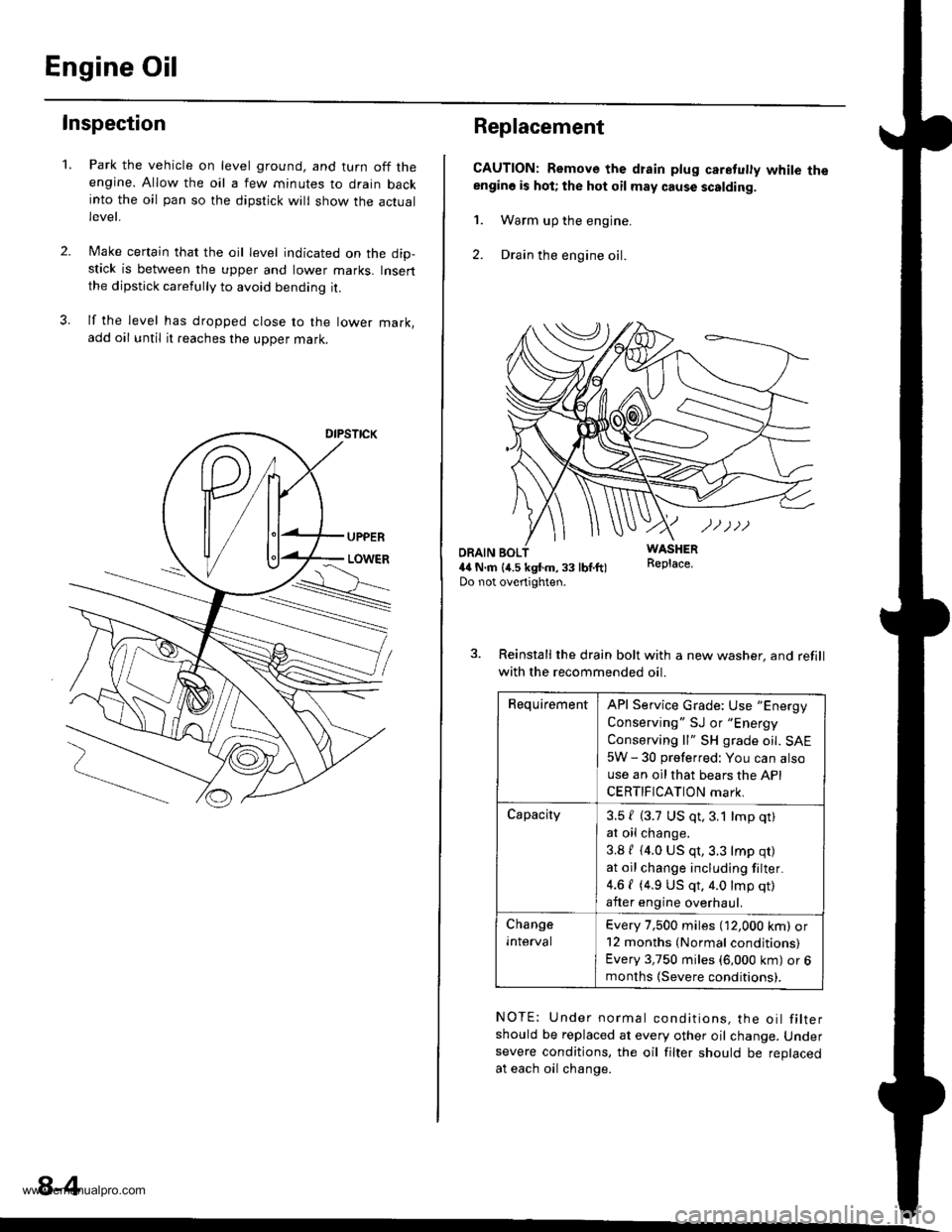
Engine Oil
Inspection
2.
1.Park the vehicle on level ground, and turn off theengine. Allow the oil a few minutes to drain backinto the oil pan so the dipstick will show the actuallevet,
Make certain that the oil level indicated on the dip-stick is between the upper and lower marks. Insertthe dipstick carefully to avoid bending it.
lf the level has dropped close to the lower mark,add oil until it reaches the upper mark.
8-4
Replacement
CAUTION: Remove the drain plug caretuly white theengino is hot; the hot oil may cause scalding.
1. Warm up the engine.
2. Drain the engine oil.
WASHERR€place.ORAIN BOL4il N.m {4.5 kgtm,33 lbf.ft)Do not overtighten.
3. Reinstall the drain bolt with a new washer, and refill
with the recommended oil.
RequirementAPI Service Grade: Use "Energy
Conserving " SJ or "Energy
Conserving ll" SH grade oil. SAE
5W - 30 preferred: You can also
use an oil that bears the API
CERTIFICATION mark.
Capacity3.5 { (3.7 US qt,3.1 lmp qt)
at oil change.
3.8 / (4.0 US qt,3.3 lmp qr)
at oil change including filter.
4.6 { (4.9 US qt, 4.0 lmp qt)
after engine overhaul.
Change
Inlerval
Every 7,500 miles (12,000 km) or12 months (Normal conditions)
Every 3,750 miles (6,000 km) or 6months (Severe conditions).
NOTE: Under normal conditions, the oil filtershould be replaced at every other oil change. Undersevere conditions, the oil filter should be replacedat each oil change.
www.emanualpro.com
Page 193 of 1395
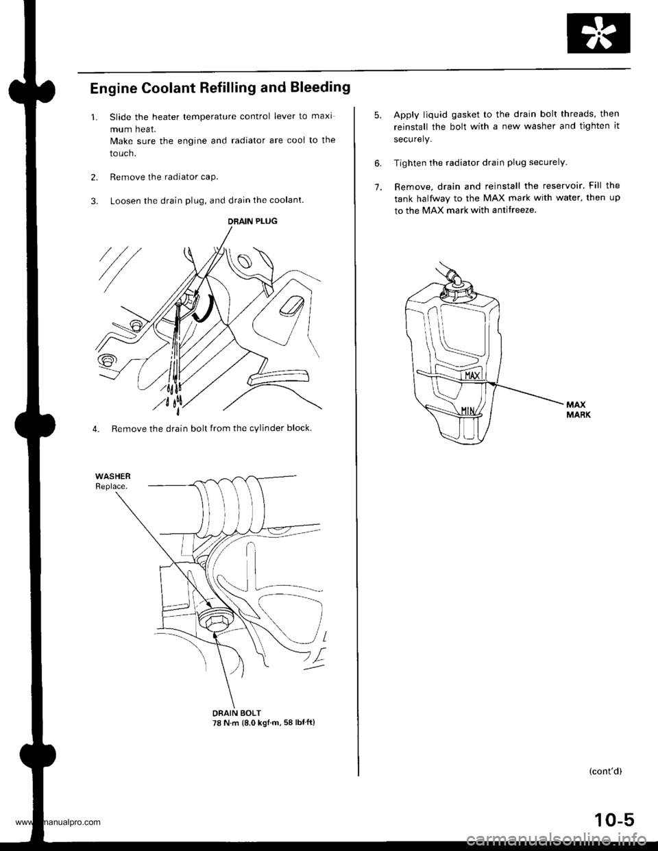
Engine Coolant Refilling and Bleeding
1. Slide the heater lemperature control lever to maxi
mum heat.
Make sure the engine and radiator are cooi to the
touch.
2. Remove the radiator caP.
3. Loosen the drain plug, and drain the coolant.
4. Remove the drain bolt from the cylinder block.
DRAIN PLUG
DRAIN BOLT78 N.m {8.0 ksl.m, 58 lbtft}
10-5
6.
7.
Apply liquid gasket to the drain bolt threads, then
reinstall the bolt with a new washer and tighten it
securely.
Tighten the radiator drain plug securely.
Remove, drain and reinstall the reservoir' Fill the
tank halfway to the MAX mark with water, then up
to the MAX mark with antitreeze.
(cont'd)
www.emanualpro.com
Page 388 of 1395
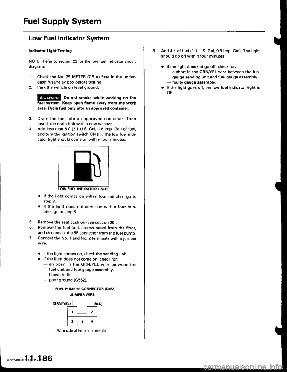
Fuel Supply System
Low Fuel Indicator System
Indicator Light Testing
NOTE: Refer to section 23forthe lowfuel lndicator circuit
clragram.
1. Check the No. 25 METER (7.5 A) fuse in the under-
dash fuse/relay box before testing.
2. Park the vehicle on level ground.
@ Do not smoke while working on the
fuel system. Keep open flame away trom the work
aroa. Drain fuel only into an approved container.
Drain the fuel into an aoDroved container. Then
install the drain bolt with a new washer.
Add less than 8 f (2.1 U.S. Gal. 1.8 lmp. Gal) of fuel,
and turn the ignition switch ON {ll). The low fuel indi-
cator light should come on within four minutes.
INDICATON LIGHT
. lf the light comes on within four minutes, go tostep 8.
. lf the light does not come on within four min-
utes. go to step 5.
Remove the seat cushion (see section 20).
Remove the fuel tank access panel from the floor,
and disconnect the 5P connector from the fuel pump,
Connect the No. 1 and No. 2 terminals with a jumper
wire.
. lf the lightcomeson, checkthe sending unit.. lf the light does not come on, check for:- an open in the GRN/yEL wire between thefuel unit and fuel gauge assembly.- blown bulb.- poor ground (G552).
FUEI- PUMP 5P CONNECTOR (C562)
JUMPER WIRE
IGRN/YEL}
7.
1 1-1 86
Wire sid€ ol tem€le terminals
8. Add 4 / of fuel (1.1 U.S. Gal, 0.9 lmp. Gal). The light
should go off within four minutes.
. lJ the light does not go off, check for:- a short in the GRNA/EL wire between the fuel
gauge sending unit and fuel gauge assembly.- faulty gauge assembly.
. lf the light goes off, the low fuel indicator light is
oK.
www.emanualpro.com
Page 393 of 1395
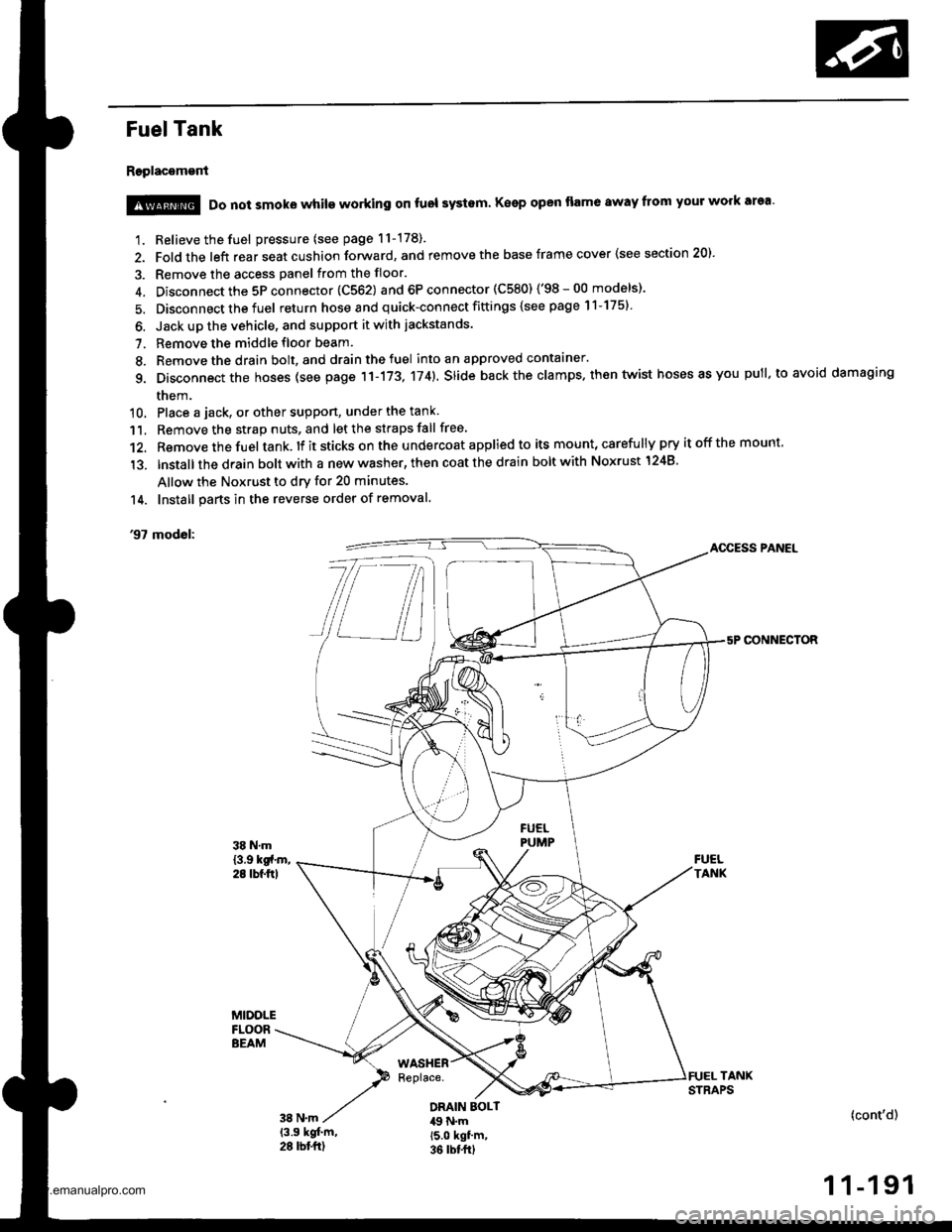
Fuel Tank
Replacement
1. Relieve the fuel pressure (see page 11-178).
2. Fold the left rear seat cushion forward, and remove the base frame cover {see section 20).
3. Remove the access panel from the floor.
4. Disconnect the 5P connector 1C562) and 6P connector (C580) ('98-00 models)'
5. Disconnect the fuel return hose and quick-connect fittings {see page 11-175}
6. Jack up the vehicle, and support it with jackstands.
7. Remove the middle floor beam.
8. Remove the drain bolt, and drain the fuel into an approved contaaner.
g. Disconnect the hoses (see page 11-173, 174). slide back the clamps. then twist hoses as you pull, to avoid damaging
them.
10. Place a jack, or other suppon, under the tank
11. Remove the strap nuts, and let the straps fall free
12. Remove the fuel tank. lf it sticks on the u ndercoat applied to its mount, carefu lly pry it off the mount,
'13. lnstallthe drain bolt with a new washer, then coat the drain bolt with Noxrust 1248'
Allow the Noxrust to dry for 20 minutes.
14. Install parts in the reverse order of removal.
'97 modol:AOCESS PANEL
CONNECTOR
@ Do not smoke while working on fuol systam Keep open flame away from your work area'
DRAIN EOLT49 N.m15.0 kgf'm,36 rbt frl
(cont'd)
1 1-191
www.emanualpro.com
Page 447 of 1395
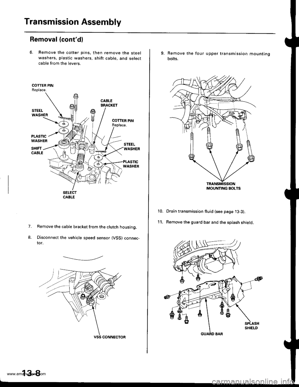
Transmission Assembly
Removal (cont'dl
6. Remove the cotter pins,
washers, plastic washers.
cable from the levers.
then remove the steel
shift cable, and select
1.
8.
Remove the cable bracket from the clutch housing.
Disconnect the vehicle speed sensor (VSS) connec-tor.
-------------.2
13-8
9. Remove the
bolts.
four upper transmission mou nting
10.
11.
Drain transmission fluid (see page '13-3).
Remove the guard bar and the splash shield.
MOUNNNG BOLTS
www.emanualpro.com
Page 452 of 1395
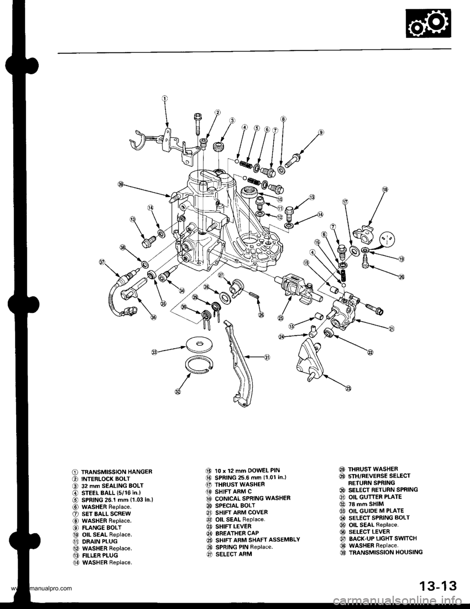
C) TRANSMISSION HANGER
O INTERLOCK BOLT
O 32 mm SEALING BOLT
@ STEEL BALL {5/16 in.)
€) SPRING 26.1 mm {1.03 in.l
@ wasHER Replace.
O sET BALL scREw
@ WASHER Replace.
€) FLANGE BOLT
@ oll SEAL Replace.
@ DRAIN PLUG
@ WASHER Replace.
@ FILLER PLUG
@ WASHER Replace.
(9 10 x 12 mm DOWEL PIN(D SPRING 25.6 mm 11.01 in.l
€' THRUST WASHER
@} SHIFT ARM C(3 CONICAL SPRING WASHER
@ SPECTAL BOLT
8] SHIFT ARM COVER
@ OIL SEAL Replace.
€! SHIFT LEVER
@I BREATHER CAP(2! SHIFT ARM SHAFT ASSEMBLY
@ SPRING PIN Replace.O SELECT ARM
€!} THRUST WASHER
@ sTH/REVERSE SELECTRETURN SPRING
@ SELECT RETURN SPRING
€) OIL GUTTER PLATE
@ 78 mm SHIM
@ OIL GUIOE M PLATE
@ SELECT SPRING BOLT
@ OIL SEAL Replace.
@ SELECT LEVER
O BACK.UP LIGHT SWITCH
@ WASHER Replace.OO TRANSMISSION HOUSING
13-13
www.emanualpro.com