drive door connector HONDA CR-V 1998 RD1-RD3 / 1.G Workshop Manual
[x] Cancel search | Manufacturer: HONDA, Model Year: 1998, Model line: CR-V, Model: HONDA CR-V 1998 RD1-RD3 / 1.GPages: 1395, PDF Size: 35.62 MB
Page 407 of 1395

'97 model:
The scan tool indicates Diagnostic Trouble Code (DTC) P0441: Evaporative Emission (EVAP) control system
insufficient purge flow.
Description
By monitoring the purge line vacuum with the MAP sensor, the PCM can detect insufficient EVAP control system purge
flow.
Possiblo Cause
. EVAP Purge Control Solenoid Valve
. EVAP Purge Control Solenoid Valve Circuit
. EVAP Control Canister
. Vacuum Lines
. PCM
Troubleshooting Flowchart
EVAP PURGE CONTROL
SO1TNOID VALVE 2P
CoNNECTOR (C108)
(v)
YL
Wire side of female
termrnals
(cont'd)
11-205
Th€ MIL has b€en reooited on.DTC P0441 is .tored.
Problem verificationl1. Start the engine. Hold theengine at 3,000 rpm with noload (in Park or neut.al) untilthe radiator fan comes on.2. Do the PCM Reset Procedure.3. Connect the SCS service con-nector,4. Test drive under following con'ditions on the road.- without any electrical load- Transmission in @ or @position- Engine speed between1 ,2OO - 2,4OO rpfi.- Decelerate from 50 mph (80
km/h)to 15 mph (24 km/h)Intermittent trilure, sydern is OKat this time. Check for Door con-nections or loose wir€3 at C108
IEVAP purge control solonoidvalvol .nd at the PCM.
ls DTC P0441 indicated?
Check tor an open in the wire (lcl
linel:1. Turn the ignition switch OFF.2. Disconnect the EVAP purge
control solenoid valve 2P con-nector.3. Turn the ignition switch ON (ll).
4. Measure voltage between bodyground and the EVAP purge
control solenoid valve 2P con-nector terminal No. '1,
R€pafu open in thc wir6 b€tw€enthG EVAP purge control solenoidvalve and the No. 15 ALTEBNA-TOR SP SENSOR (7.5 A)fuse.
ls there batlery voltage?
(To page 11'206)
www.emanualpro.com
Page 1038 of 1395
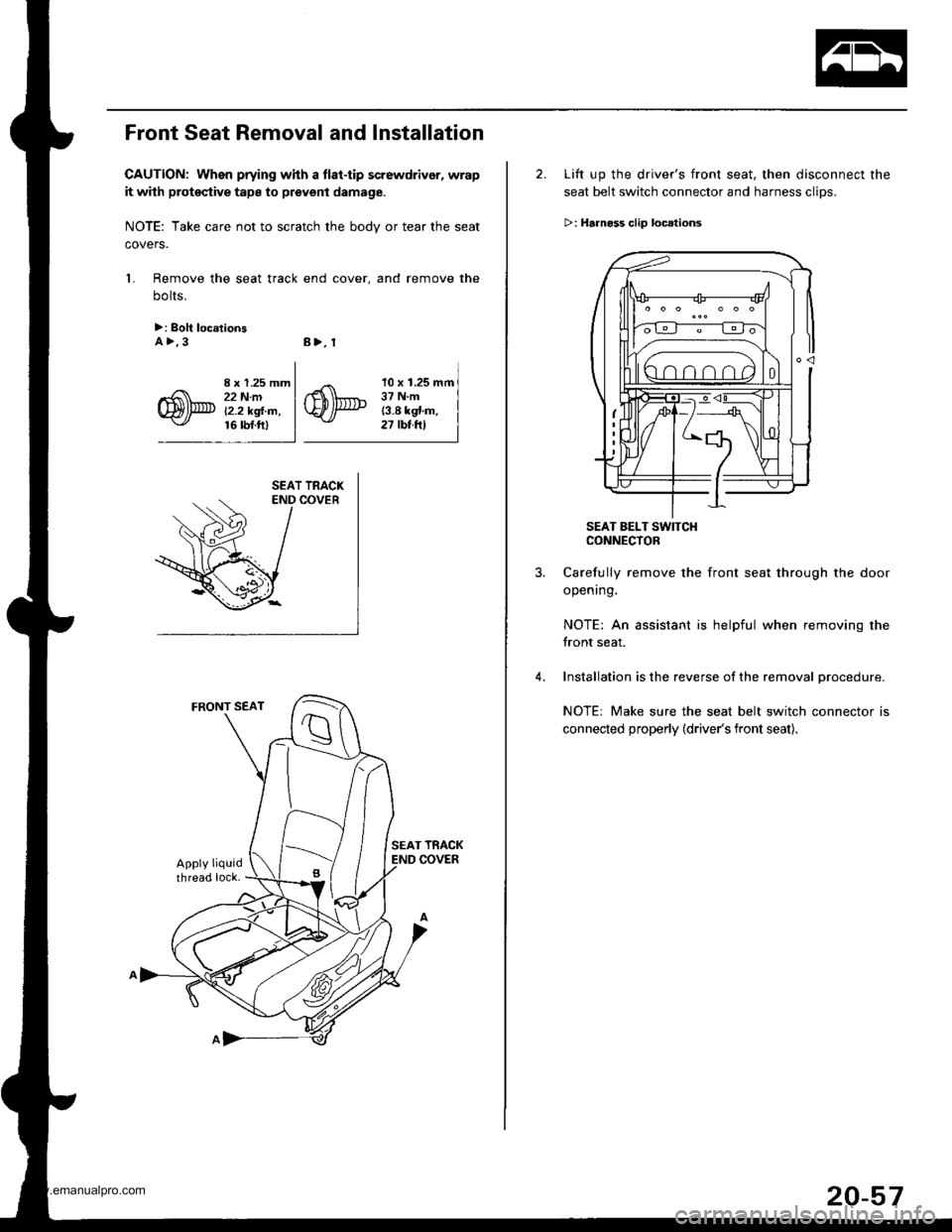
Front Seat Removal and Installation
CAUTION: When prying whh a tlat-tip screwdrivor, wrap
it with proteqtive tape to prevent damage.
NOTE: Take care not to scratch the bodv or tear the seat
covers.
1. Remove the seat track end cover, and remove the
bolts.
>: Bolt loc.tionsA>.3B>, 1
I x 1.25 mm22 N.mi'2.2 kgl.m,16 rbf.ftl
10 x 1.25 mm37 N.m13.8 kgt.m,27 tbt.ftl
2. Lift up the driver's front seat, then disconnect the
seat belt switch connector and harness clips.
>: Hrrnoss clip loc.lions
SEAT BELT SW]TCHCONNECTOR
Carefully remove the front seat through the door
opening.
NOTE: An assistant is helpful when removing the
front seat.
Installation is the reverse of the removal procedure.
NOTE: Make sure the seat belt switch connector is
connected properly (driver's front seat).
20-57
www.emanualpro.com
Page 1171 of 1395

Gonnector ldentification and Wire Harness Routing
How to ldentity Connectors:
ldentification numbers have been assigned to all connectors, The number is preceded by the letter "C" for connectors.
"G" for ground terminals or "T" for non-ground terminals.
Location
HarnessEngine CompartmsntDashboardOthers lFloor, Door,
8oof, Tailgate)
Starter cableT1, T2 and @
Battery ground cableG1 and O
Engine ground cableT3
Transmission ground cableT4
G3
Engine wire harnessC101 through C137
T101 and T102
G101
Engine compartment ware harnessC201 through C218
G201 and G202
Under-hood ABS fuse/relay box
wire harness
t5ano9
Main wire harnessC301 through C309
C351 through C361
C401 through C447
G401 and G402
Dashboard wire harnessC501 through C524 (C525)
G501
Left side wire harnessC551 through C581
G551, G552 and G553
Right side wire harnessC601 through C605
lnterior wire harnessC701 through C703
Rear bumper wire harnessC641 through C643
Heater sub-harnessC731 through C740
Secondary heated oxygen sensor
sub-harness
C721 through C722
Combination switch sub-harnessC751 through C760
Driver's door wire harnessC661 through C667
Front passenger's door wire harnessC6Tl through C676
Left rear door wire harnessC681 through C684
Right rear door wire harnessC69'l through C694
Rear wire harnessC611 through C520
Tailgate wire harnessC631 through C634
G631
SRS main harnessC801 through C808
G801
High mount brake light sub-harnessC651 through C653
Fuel tank oressure sensor sub-harnessC645 through C647
www.emanualpro.com
Page 1186 of 1395

Connector ldentification and Wire Harness Routing
Left Side Wire Harness
Connector oI
Terminal
Number of
CavitiesLocaiionConnects toNot6s
c551
c552
c554
c556
c558
c559
c559
c560
c562
c563
c563
c564
c565
c566
c568
c569
c570
c572
c573
c57 4
c575
c576
c578
c579
c580
c581
8
16
10
14'I
14
16
20
20
24
)
1
5
1
1
6
1
2
14
1
1
6
1
6
Behind under-dash fuse/relay box
Behind under-dash fuse/relay box
Left side of steering wheel
Left side of steering wheel
Left side of steering wheel
Above under-dash fuse/relay box
Above under-dash fuse/relay box
Driver's door
Behind left kick panel
Behind left kick panel
Behind left kick panel
Left side offloor
Left quaner panel
Fueltank
On left half of rear cross beam
On left half of rear cross beam
Left quarter panel
Left quarter panel
Left quarter panel
Left quarter panel
Left quarter panel
Left quarter panel
On left half of rear cross beam
Right quarter panel
Right quarter panel
Left quarter pillar
Left side of floor
Left B-piller
Left B-piller
Behind left kick panel
Behind left kick panel
Under left side of dash
Left B-piller
Fueltank
Left side of steering wheel
Under-dash fuse/relay box (C921)
Under-dash fuse/relay box (C923)
Power mirror switch
Power window master switch
Power window master switch
Dashboard wire harness {C505)
Dashboard wire harness 1C505)
Driver's door wire harness (C661)
Main wire harness (C403)
Main wire harness (C404)
Main wire harness (C404)
Driver's seat belt switch
Left rear door switch
Fuel unit
Left rear ABS wheel sensor
Left rear ABS wheel sensor
Rear accessory socket connector {+}
Rear accessory socket connector (-)
Rear bumper wire harness 1C641)
Trailer lighting connector
Tailgate door latch switch
Left rear speaker
Right rear ABS wheel sensor
Rear wire harness (C611)
Right rea. door switch
Left taillight
Parking brake switch
Left rear door wire harness (C681)
Driver's door switch
Select unlock relay (for security alarm
system)
Junction connector (for power door
locks)
SRS main harness (C807)
Driver's seat belt tensioner
Fuel tank pressure sensor sub-harness(c645)
Power window master switch
'97 - 98
mooets'99 - 00
models
'97 model'98 - 00
models
Optional
'97 model'98 - 00
models
'98 - 00
mooets'98 - 00
models'98 - 00
mooets'99 - 00
mooets
G551
G553
Behind left kick panel
Left side ot floor
Left quarter piller
Body ground, via left side wire harness
Body ground, via left side wire harness
Body ground, via left side wire harness
23-26
www.emanualpro.com
Page 1192 of 1395
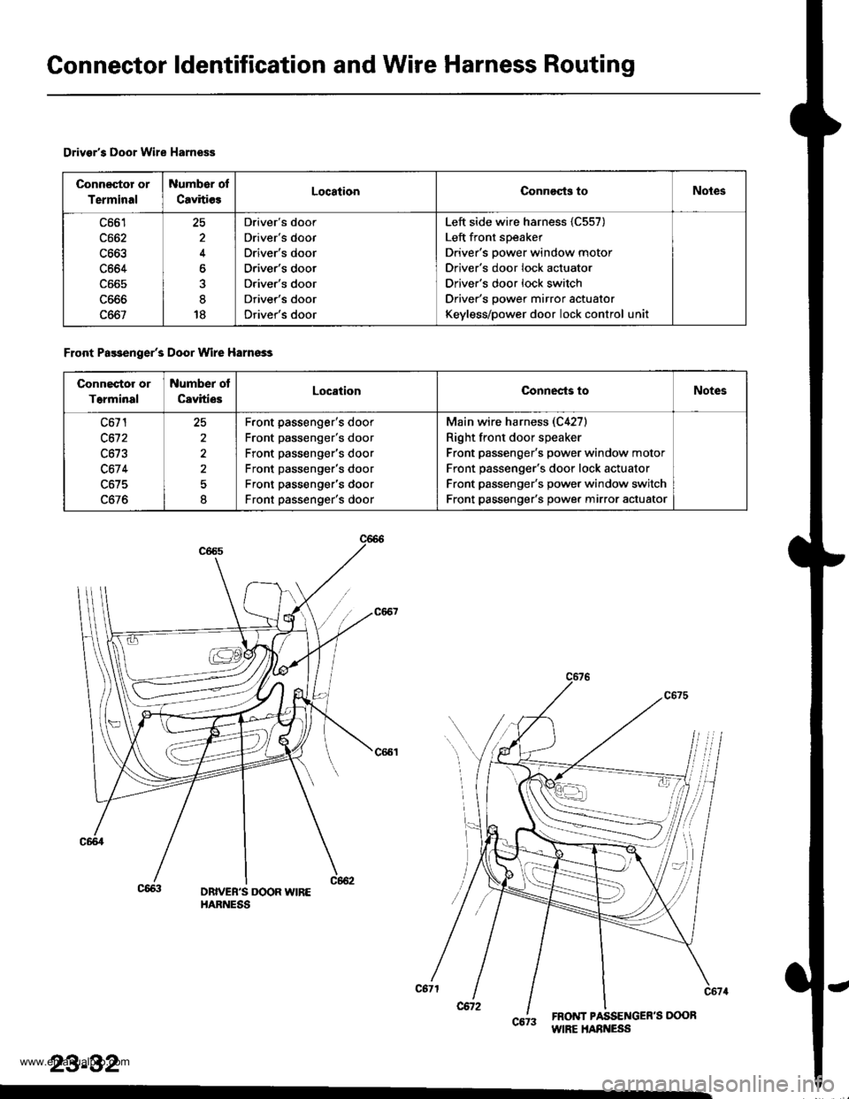
Connector ldentification and Wire Harness Routing
Drivsr's Door Wire Harness
Connector or
Terminal
Number of
CavitiesLocationConnocts toNotes
c664
c667
25
4
at
18
Driver's door
Driver's door
Driver's door
Driver's door
Driver's door
Driver's door
Driver's door
Left side wire harness {C557)
Left front speaker
Driver's power window motor
Driver's door lock actuator
Driver's door lock switch
Driver's power mirror actuator
Keyless/power door lock control uni
Front Pa$enger's Door Wire Harnsss
Connector or
T6rminal
Number ot
CavitiesLocationConnects toNotes
c671
c612
c67 4
c675
2^
I
Front passenger's door
Front passenger's door
Front passenger's door
Front passenger's door
Front passenger's door
Front passenger's door
Main wire harness (C4271
Right front door speaker
Front passenger's power window motor
Front passenger's door lock actuator
Front passenger's power window switch
Front passenger's power mirror actuator
DBIVEB'S DOOR WIREHARNESS
6tt inliiioint""
23-32
www.emanualpro.com
Page 1208 of 1395
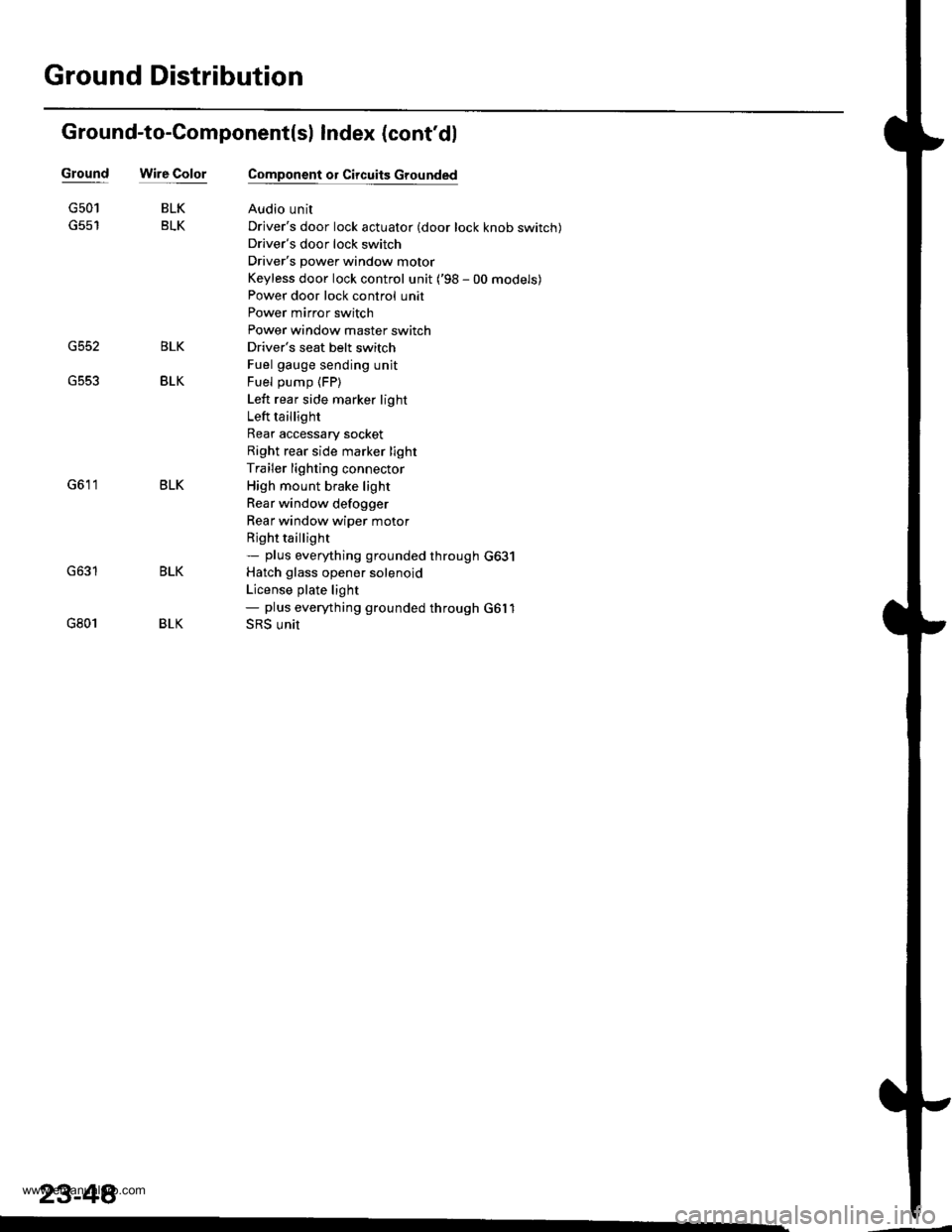
Ground Distribution
Ground-to-Component(sl Index (cont'dl
Wire ColorGround
G552
G501
G801
BLK
BLK
BLK
BLK
Component or Circuits Grounded
Audio unit
Driver's door lock actuator (door lock knob switch)
Driver's door lock switch
Driver's power window motor
Keyless door lock control unit ('98 - 00 models)
Power door lock control unit
Power mirror switch
Power window master switch
Driver's seat belt switch
Fuel gauge sending unit
Fuel pump (FP)
Left rear side marker light
Left taillight
Rear accessary socket
Right rear side marker light
Trailer lighting connector
High mount brake light
Rear window defogger
Rear window wiper motor
Rjght taillight- plus eveMhing grounded through G631
Hatch glass opener solenoid
License plate light- plus eveMhing grounded through G6l1
SRS unit
BLK
BLK
BLK
23-48�
www.emanualpro.com
Page 1238 of 1395
Lighting System
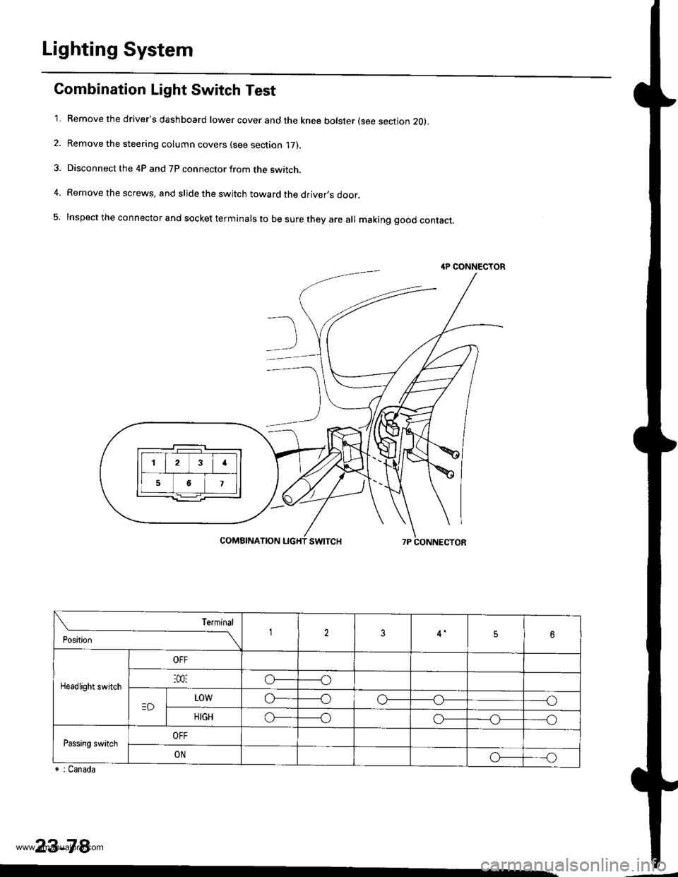
Combination Light Switch Test
'1. Remove the driver's dashboard lower cover and the knee bolster (see section 20).
2. Remove the steering column covers (see section '17).
3. Disconnect the 4P and 7P connector from the switch.
4. Remove the screws, and slide the switch toward the driver,s door,
5. Inspect the connector and socket terminals to be sure they are all making good contact.
r : Canada
23-78
4P CONNECTOR
23I
56
Position
Terminal12356
Headlight switch
OFF
:m:o_----o
=DL0wo------oo-----o
HIGHo_----oo-_--_o_----o
Passing switchOFF
ONo_---o
www.emanualpro.com
Page 1247 of 1395
![HONDA CR-V 1998 RD1-RD3 / 1.G Workshop Manual
Turn Signal Switch Test
1.
4.
Remove the drivers dashboard lower cover and the
knee bolster (see section 20).
Remove the steering column covers {see section
17]-.
Disconnect the 4P and 7P connectors HONDA CR-V 1998 RD1-RD3 / 1.G Workshop Manual
Turn Signal Switch Test
1.
4.
Remove the drivers dashboard lower cover and the
knee bolster (see section 20).
Remove the steering column covers {see section
17]-.
Disconnect the 4P and 7P connectors](/img/13/5778/w960_5778-1246.png)
Turn Signal Switch Test
1.
4.
Remove the driver's dashboard lower cover and the
knee bolster (see section 20).
Remove the steering column covers {see section
17]-.
Disconnect the 4P and 7P connectors from the
switch.
Remove the screws, and slide the switch toward the
driver's door.
Check for continuity between the terminals in each
switch position according to the table.
Position
Terminal12
RIGHTo-
Neutral
LEFTo---o
q
tl-
swtTcH
Hazard Warning Switch Test
1. Remove the center panel {see section 20).
2. Remove the two screws, then remove the switch
from the center air vent.
HAZARD
Check for continuitv between the terminals in each
switch position according to the table.
Terminal
t**--\
2357810
OFF(9U(_)
ONo@oooo
lNol us€d)
23-87
www.emanualpro.com
Page 1249 of 1395
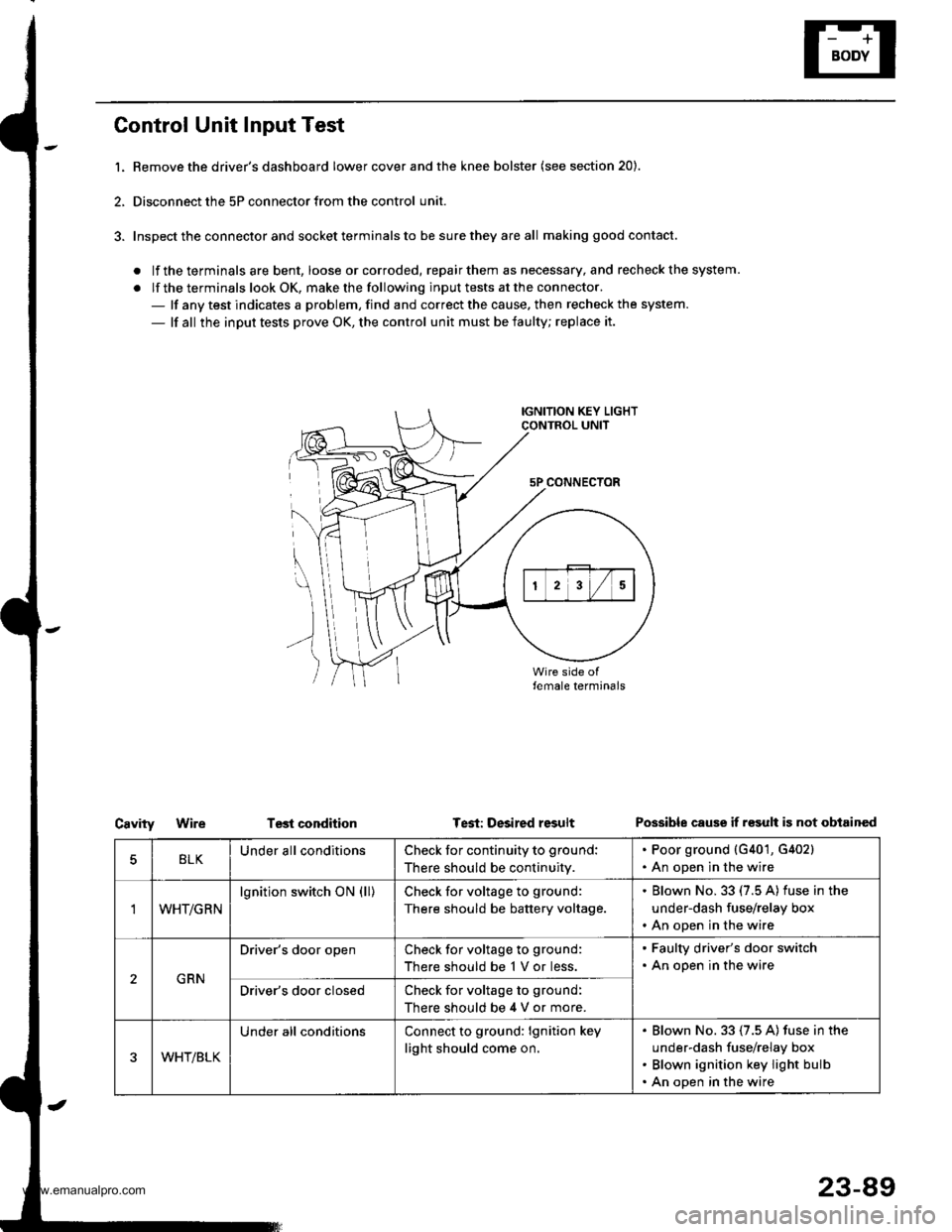
Control Unit Input Test
l. Bemove the driver's dashboard lower cover and the knee bolster (see section 20).
2, Disconnect the 5P connector from the control unit.
3. Inspect the connector and socket terminals to be sure they are all making good contact.
. lf the terminals are bent, loose orcorroded, repairthem as necessary, and recheck the system.
. lf the terminals look OK, make the following input tests at the connector.- lf any test indicates a problem, find and correct the cause. then recheck the system.
- lf all the input tests prove OK, the control unit must be faulty; replace it.
IGNITION KEY LIGHTCONTROL UNIT
5P CONNECTOR
\
))
Test conditionCavityWireTest: Desired resultPossible cause if r€sult is not obtained
BLKUnder all conditionsCheck for continuity to ground:
There should be continuity.
. Poor ground {G401, G402}. An open in the wire
'IWHT/GRN
lgnition switch ON (ll)Check for voltage to ground:
There should be battery voltage.
. Blown No. 33 (7.5 A) fuse in the
under-dash fuse/relay box. An open in the wire
GRN
Driver's door openCheck for voltage to ground:
There should be 1 V or less.
. Faulty driver's door switch. An open in the wire
Driver's door closedCheck for voltage to ground:
There should be 4 V or more.
WHT/BLK
Under all conditionsConnect to ground: lgnition key
light should come on.
Blown No. 33 (7.5 A) fuse in the
under-dash fuse/relay box
Blown ignition key light bulb
An open in the wire
23-89
www.emanualpro.com
Page 1286 of 1395
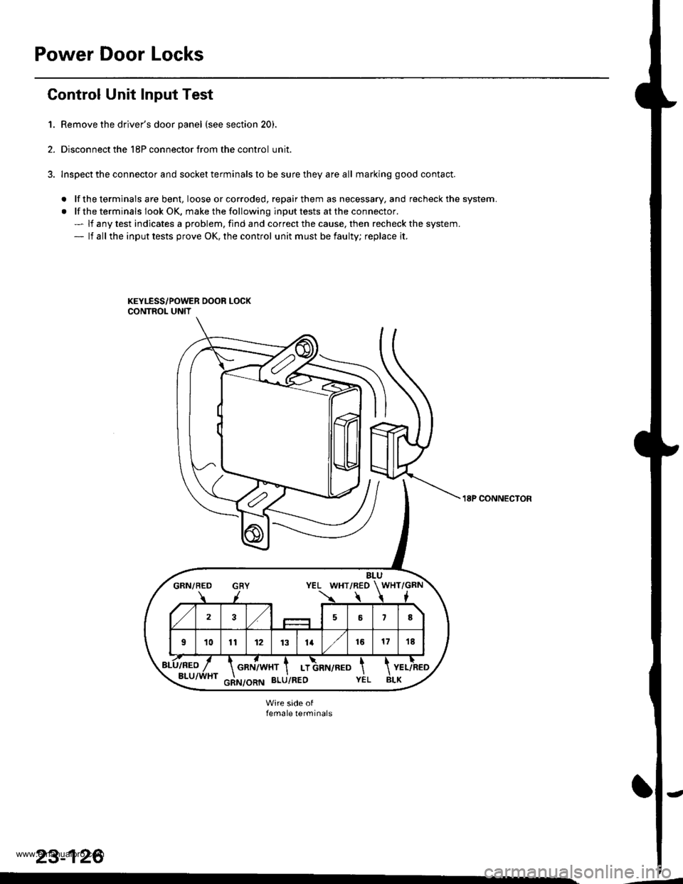
Power Door Locks
Gontrol Unit Input Test
1. Remove the driver's door panel (see section 20).
2. Disconnect the 18P connector from the control unit.
3. lnspect the connector and socket terminals to be sure they are all marking good contact.
. lf the terminals are bent, loose orcorroded, repairthem as necessary, and recheck the system.
. lf the terminals look OK, make the following input tests at the connector.- lf any test indicates a problem, find and correct the cause, then recheck the system.- lf all the input tests prove OK, the control unit must be faulty; replace it.
BLUGRN/BED GRY YEL WHT/REO WHT/GRN
723,/58
101t12 1131416171E
GRN/WHT I LT
18P CONNECTON
female terminals
23-126
www.emanualpro.com